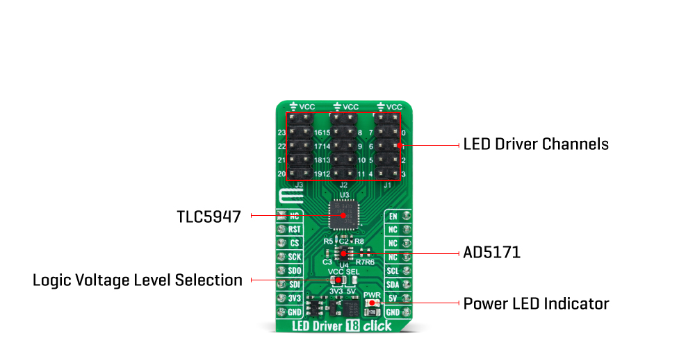
The LED Driver 18 Click Board™ is based on the TLC5947, a 24-channel 12-bit PWM LED driver from Texas Instruments. Each channel supports many LEDs in series connected to the LED terminal, and has an individually-adjustable 4096-step PWM grayscale brightness control accessible through a serial interface port. It has a programmable current value of all 24 channels achievable through the AD5171, an I2C-configurable digital potentiometer, with a maximum of 30mA of LED current per channel. The TLC5947 also features a built-in thermal shutdown function that turns OFF all output drivers during an over-temperature condition. All channels automatically restart when the temperature returns to normal conditions.
The LED Driver 18 Click Board™ communicates with MCU through a register-selectable standard SPI interface that enables a high clock speed of up to 30MHz for optimum performance. In addition to the interface signals, the TLC5947 uses another signal from the mikroBUS™ socket. The enable signal routed on the EN pin of the mikroBUS™ socket provides the ability to turn OFF all constant-current outputs. When the EN pin is in a high logic state, all channels (0-23) are forced OFF, the grayscale PWM timing controller initializes, and the grayscale counter resets to 0. When the EN pin is in a low logic state is low, the grayscale PWM timing controller controls all LED channels.
The LED Driver 18 Click Board™ can operate with either 3.3V or 5V logic voltage levels selected via the VCC SEL jumper. This way, both 3.3V and 5V capable MCUs can use the communication lines properly. However, the Click board™ comes equipped with a library containing easy-to-use functions and an example code that can be used, as a reference, for further development.
| Type | LED Drivers |
| Applications | Can be used for color mixing and backlight application for amusement products, LED status signalization, home automation projects, and more |
| On-board modules | TLC5947 - PWM LED driver from Texas Instruments |
| Key Features | 24 LED channels, programmable current value, PWM grayscale control, thermal shutdown protection, low power consumption, high efficiency and performance, and more |
| Interface | I2C,SPI |
| Compatibility | mikroBUS |
| Click board size | M (42.9 x 25.4 mm) |
| Input Voltage | 3.3V or 5V |
This table shows how the pinout of the LED Driver 18 Click Board™ corresponds to the pinout on the mikroBUS™ socket (the latter shown in the two middle columns).
| Notes | Pin | Pin | Notes | ||||
|---|---|---|---|---|---|---|---|
| NC | 1 | AN | PWM | 16 | EN | Channels Enable | |
| NC | 2 | RST | INT | 15 | NC | ||
| SPI Chip Select | CS | 3 | CS | RX | 14 | NC | |
| SPI Clock | SCK | 4 | SCK | TX | 13 | NC | |
| SPI Data OUT | SDO | 5 | MISO | SCL | 12 | SCL | I2C Clock |
| SPI Data IN | SDI | 6 | MOSI | SDA | 11 | SDA | I2C Data |
| Power Supply | 3.3V | 7 | 3.3V | 5V | 10 | 5V | Power Supply |
| Ground | GND | 8 | GND | GND | 9 | GND | Ground |
| Label | Name | Default | Description |
|---|---|---|---|
| LD1 | PWR | - | Power LED Indicator |
| JP1 | VCC SEL | Left | Logic Level Voltage Selection 3V3/5V: Left position 3V3, Right position 5V |
| J1-J3 | 0-23 | Populated | LED Driver Channel Terminals |
| Description | Min | Typ | Max | Unit |
|---|---|---|---|---|
| Supply Voltage | 3.3 | - | 5 | V |
| Output Current | - | - | 30 | mA |
| Resolution | - | 12 | - | bit |
We provide a library for the LED Driver 18 Click Board™ as well as a demo application (example), developed using MikroE compilers. The demo can run on all the main MikroE development boards.
The package can be downloaded/installed directly from NECTO Studio The package Manager (recommended), downloaded from our LibStock™ or found on MikroE Github account.
Library Description
This library contains API for LED Driver 18 Click driver.
Key functions
leddriver18_set_output_pwm LED Driver 18 set output channel PWM value function.
leddriver18_write_config LED Driver 18 write config function.
leddriver18_set_cc_output LED Driver 18 set constant current output function.
Example Description
This library contains API for the LED Driver 18 Click Board™ driver. The library initializes and defines the I2C bus drivers to write and read data for setting constant current output, as well as the default configuration for a PWM output value of the OUT channels.
void application_task ( void )
 {
     float pwm_val;

     for ( int8_t  n_cnt = 0; n_cnt <= 100; n_cnt += 10 )
     {
         for ( uint8_t out_cnt = 0; out_cnt < LEDDRIVER18_MAX_OUTPUT_NUM; out_cnt++ )
         {
             leddriver18_set_output_pwm( out_cnt, n_cnt );
         }
         pwm_val = leddriver18_get_output_pwm( 0 );
         log_printf( &logger, " PWM value: %.2f rn", pwm_val );
         leddriver18_write_config( &leddriver18 );
         Delay_ms( 200 );
     }
     for ( int8_t  n_cnt = 100; n_cnt >= 10; n_cnt -= 10 )
     {
         for ( uint8_t out_cnt = 0; out_cnt < LEDDRIVER18_MAX_OUTPUT_NUM; out_cnt++ )
         {
             leddriver18_set_output_pwm( out_cnt, n_cnt );
         }
         pwm_val = leddriver18_get_output_pwm( 0 );
         log_printf( &logger, " PWM value: %.2f rn", pwm_val );
         leddriver18_write_config( &leddriver18 );
         Delay_ms( 200 );
     }
 }
The full application code, and ready to use projects can be installed directly from NECTO Studio The package Manager (recommended), downloaded from our LibStock™ or found on MikroE Github account.
Other MikroE Libraries used in the example:
Additional Notes and Information
Depending on the development board you are using, you may need USB UART Click Board™, USB UART 2 Click or RS232 Click to connect to your PC, for development systems with no UART to USB interface available on the board. UART terminal is available in all MikroE compilers.
The LED Driver 18 Click Board™ is supported with mikroSDK - MikroE Software Development Kit, which needs to be downloaded from the LibStock and installed for the compiler you are using to ensure proper operation of mikroSDK compliant Click board™ demo applications.
- manufacturer: Mikroelektronika d.o.o. - warranty: 12 months - backorder_label: If no stock shown above, check availability - attachments: [{"download_file":[{"download_file":"LED Driver 18 Click Board™ Schematic"}],"download_filetype":[{"download_filetype":"pdf"}]},{"download_file":[{"download_file":"Analog Devices AD5171 Digital Potentiometer Datasheet"}],"download_filetype":[{"download_filetype":"pdf"}]},{"download_file":[{"download_file":"Texas Instruments TLC5947 LED Driver Datasheet"}],"download_filetype":[{"download_filetype":"pdf"}]}] - device_vendor: Analog Devices Inc., Texas Instruments - device_type: AD5171BRJZ50-R2, TLC5947RHBR - warranty: 12 months - brand: MikroE - manufacturer: Mikroelektronika d.o.o. - target_keyword: LED Driver 18 Click Board - brands: gid://shopify/Metaobject/56256004319 - breadcrumbs: ["gid://shopify/Collection/447955239135","gid://shopify/Collection/241680580797","gid://shopify/Collection/241544822973"] - mpn: MIKROE-5560 - customhs_code: 847330 - detailed_description: {"type":"root","children":[{"type":"heading","level":3,"children":[{"type":"text","value":"How Does The LED Driver 18 Click Board™ Work?"}]},{"type":"paragraph","children":[{"type":"text","value":"The "},{"type":"text","value":"LED Driver 18 Click Board™","bold":true},{"type":"text","value":" is based on the TLC5947, a 24-channel 12-bit PWM LED driver from Texas Instruments. Each channel supports many LEDs in series connected to the LED terminal, and has an individually-adjustable 4096-step PWM grayscale brightness control accessible through a serial interface port. It has a programmable current value of all 24 channels achievable through the AD5171, an I2C-configurable digital potentiometer, with a maximum of 30mA of LED current per channel. The TLC5947 also features a built-in thermal shutdown function that turns OFF all output drivers during an over-temperature condition. All channels automatically restart when the temperature returns to normal conditions."}]},{"type":"paragraph","children":[{"type":"text","value":""}]},{"type":"paragraph","children":[{"type":"text","value":"The "},{"type":"text","value":"LED Driver 18 Click Board™","bold":true},{"type":"text","value":" communicates with MCU through a register-selectable standard SPI interface that enables a high clock speed of up to 30MHz for optimum performance. In addition to the interface signals, the TLC5947 uses another signal from the mikroBUS™ socket. The enable signal routed on the EN pin of the mikroBUS™ socket provides the ability to turn OFF all constant-current outputs. When the EN pin is in a high logic state, all channels (0-23) are forced OFF, the grayscale PWM timing controller initializes, and the grayscale counter resets to 0. When the EN pin is in a low logic state is low, the grayscale PWM timing controller controls all LED channels."}]},{"type":"paragraph","children":[{"type":"text","value":"The "},{"type":"text","value":"LED Driver 18 Click Board™","bold":true},{"type":"text","value":" can operate with either 3.3V or 5V logic voltage levels selected via the VCC SEL jumper. This way, both 3.3V and 5V capable MCUs can use the communication lines properly. However, the Click board™ comes equipped with a library containing easy-to-use functions and an example code that can be used, as a reference, for further development."}]},{"type":"heading","level":3,"children":[{"type":"text","value":"SPECIFICATIONS"}]},{"type":"paragraph","children":[{"type":"text","value":"Type\nLED Drivers\nApplications\nCan be used for color mixing and backlight application for amusement products, LED status signalization, home automation projects, and more\nOn-board modules\nTLC5947 - PWM LED driver from Texas Instruments\nKey Features\n24 LED channels, programmable current value, PWM grayscale control, thermal shutdown protection, low power consumption, high efficiency and performance, and more\nInterface\nI2C,SPI\nCompatibility\nmikroBUS\nClick board size\nM (42.9 x 25.4 mm)\nInput Voltage\n3.3V or 5V"}]},{"type":"heading","level":3,"children":[{"type":"text","value":"PINOUT DIAGRAM"}]},{"type":"paragraph","children":[{"type":"text","value":"This table shows how the pinout of the "},{"type":"text","value":"LED Driver 18 Click Board™","bold":true},{"type":"text","value":" corresponds to the pinout on the mikroBUS™ socket (the latter shown in the two middle columns)."}]},{"type":"paragraph","children":[{"type":"text","value":"Notes\nPin\nPin\nNotes\nNC\n1\nAN\nPWM\n16\nEN\nChannels Enable\nNC\n2\nRST\nINT\n15\nNC\nSPI Chip Select\nCS\n3\nCS\nRX\n14\nNC\nSPI Clock\nSCK\n4\nSCK\nTX\n13\nNC\nSPI Data OUT\nSDO\n5\nMISO\nSCL\n12\nSCL\nI2C Clock\nSPI Data IN\nSDI\n6\nMOSI\nSDA\n11\nSDA\nI2C Data\nPower Supply\n3.3V\n7\n3.3V\n5V\n10\n5V\nPower Supply\nGround\nGND\n8\nGND\nGND\n9\nGND\nGround"}]},{"type":"heading","level":3,"children":[{"type":"text","value":"ONBOARD SETTINGS AND INDICATORS"}]},{"type":"paragraph","children":[{"type":"text","value":"Label\nName\nDefault\nDescription\nLD1\nPWR\n-\nPower LED Indicator\nJP1\nVCC SEL\nLeft\nLogic Level Voltage Selection 3V3/5V: Left position 3V3, Right position 5V\nJ1-J3\n0-23\nPopulated\nLED Driver Channel Terminals"}]},{"type":"heading","level":3,"children":[{"type":"text","value":"LED DRIVER 18 CLICK ELECTRICAL SPECIFICATIONS"}]},{"type":"paragraph","children":[{"type":"text","value":"Description\nMin\nTyp\nMax\nUnit\nSupply Voltage\n3.3\n-\n5\nV\nOutput Current\n-\n-\n30\nmA\nResolution\n-\n12\n-\nbit"}]}]} - summary:Introducing the LED Driver 18 Click Board, the compact add-on board that simplifies the control of multiple LEDs. With the powerful TLC5947 LED driver from Texas Instruments, this board allows for individual adjustment of 24 channels with 4096 pulse-width modulated (PWM) steps. Each channel also has a programmable current value of up to 30mA of LED current per channel.
The LED Driver 18 Click Board features a 24-channel LED driver from Texas Instruments with 4096 pulse-width modulated (PWM) steps. Each channel also has a programmable current value of up to 30mA of LED current per channel. Additionally, the board includes a built-in thermal shutdown function for added safety.
This Click board™ is perfect for a variety of applications, including color mixing and backlight applications, LED status signalization, home automation projects, and more!
The built-in thermal shutdown function turns off all output drivers during an over-temperature condition, ensuring the safety and longevity of your LEDs. Plus, with its mikroSDK-compliant library, software development is easier than ever.
Order your LED Driver 18 Click Board today and experience simplified control of multiple LEDs. This fully tested product is ready to be used on any system equipped with the mikroBUS™ socket.