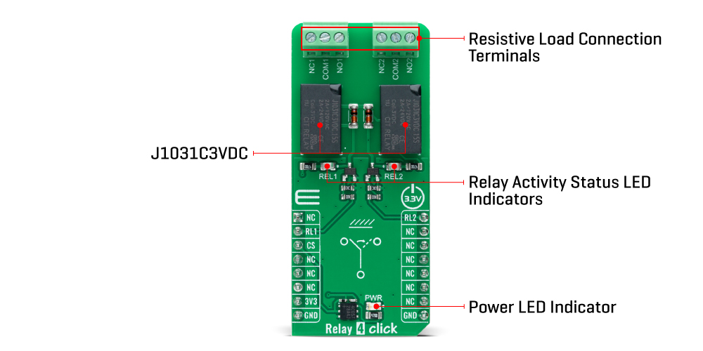
The Relay 4 Click Board™ is based on dual J1031C3VDC, high-current single-pole double-throw (SPDT) signal relays from CIT Relay and Switch. The J1031C3VDC relay is well known for its reliability and durability, high sensitivity, and low coil power consumption housed in a small package with PC pin mounting. Despite its size (12.5x7.5x10 millimetre (LxWxH)), the J1031C3VDC relay can withstand up to 2A and 125VAC/60VDC maximum. These relays are designed to easily activate their coils by relatively low currents and voltages, making them a perfect choice that any MCU can control.
As mentioned, the contact configuration of the J1031C3VDC is a single-pole double-throw (SPDT), which means that it has one pole and two throws. Based on the default position of the pole, one throw is considered normally open (NO) while the other is normally closed (NC), which is, in this case, its default position. When the coil is energized, it will attract the internal switching elements similar to a switch.
The Relay 4 Click Board™ uses two mikroBUS™ pins for its proper operation, the RL1 and RL2 pins routed to the RST and PWM pins of the mikroBUS™ socket. These pins control small N-channel MOSFET RET (Resistor Equipped Transistor) transistors that provide enough current for the relay coil. Two resistors are already integrated into the RET, providing it with the correct biasing and simplifying the design. Also, each relay has its own yellow LED indicator, which signalizes the state of the relay. When the current flows through the RET, the coil will be energized, and the relay will be switched from a closed to an open switch state.
The Relay 4 Click Board™ can be operated only with a 3.3V logic voltage level. The board must perform appropriate logic voltage level conversion before using MCUs with different logic levels. However, the Click board™ comes equipped with a library containing functions and an example code that can be used as a reference for further development.
| Type | Relay |
| Applications | Can be used for controlling high-power applications |
| On-board modules | J1031C3VDC - general-purpose signal relay from CIT Relay and Switch |
| Key Features | Low power consumption, reliable switching, high current, hig sensitivity, PC board mounting, SPDT configuration, relay activity indicators, and more |
| Interface | GPIO |
| Compatibility | mikroBUS |
| Click board size | L (57.15 x 25.4 mm) |
| Input Voltage | 3.3V |
This table shows how the pinout of the Relay 4 Click Board™ corresponds to the pinout on the mikroBUS™ socket (the latter shown in the two middle columns).
| Notes | Pin | Pin | Notes | ||||
|---|---|---|---|---|---|---|---|
| NC | 1 | AN | PWM | 16 | RL2 | Relay 2 Control | |
| Relay 1 Control | RL1 | 2 | RST | INT | 15 | NC | |
| NC | 3 | CS | RX | 14 | NC | ||
| NC | 4 | SCK | TX | 13 | NC | ||
| NC | 5 | MISO | SCL | 12 | NC | ||
| NC | 6 | MOSI | SDA | 11 | NC | ||
| Power Supply | 3.3V | 7 | 3.3V | 5V | 10 | NC | |
| Ground | GND | 8 | GND | GND | 9 | GND | Ground |
| Label | Name | Default | Description |
|---|---|---|---|
| LD1 | PWR | - | Power LED Indicator |
| LD2-LD3 | REL1-REL2 | - | Relay Activity Status LED Indicators |
| Description | Min | Typ | Max | Unit |
|---|---|---|---|---|
| Supply Voltage | - | 3.3 | - | V |
| Current Rating | - | - | 2 | A |
| Switching Voltage | - | - | 60 | VDC |
We provide a library for the Relay 4 Click Board™ as well as a demo application (example), developed using MikroE compilers. The demo can run on all the main MikroE development boards.
The package can be downloaded/installed directly from NECTO Studio The package Manager(recommended), downloaded from our LibStock™ or found on MikroE Github account.
Library Description
This library contains API for the Relay 4 Click Board™ driver.
Key functions
relay4_set_relay1_open This function sets the relay 1 to normally open state by setting the RL1 pin to low logic level.
relay4_set_relay1_close This function sets the relay 1 to normally close state by setting the RL1 pin to high logic level.
relay4_set_relay2_open This function sets the relay 2 to normally open state by setting the RL2 pin to low logic level.
Example Description
This example demonstrates the use of the Relay 4 Click Board™ by toggling the relays state.
void application_task ( void )
 {
     relay4_set_relay1_open ( &relay4 );
     log_printf( &logger, " Relay 1 set to normally open statern" );
     relay4_set_relay2_close ( &relay4 );
     log_printf( &logger, " Relay 2 set to normally close staternn" );
     Delay_ms ( 5000 );

     relay4_set_relay1_close ( &relay4 );
     log_printf( &logger, " Relay 1 set to normally close statern" );
     relay4_set_relay2_open ( &relay4 );
     log_printf( &logger, " Relay 2 set to normally open staternn" );
     Delay_ms ( 5000 );
 }
The full application code, and ready to use projects can be installed directly from NECTO Studio The package Manager(recommended), downloaded from our LibStock™ or found on MikroE Github account.
Other MikroE Libraries used in the example:
Additional Notes and Information
Depending on the development board you are using, you may need USB UART Click Board™, USB UART 2 Click or RS232 Click to connect to your PC, for development systems with no UART to USB interface available on the board. UART terminal is available in all MikroE compilers.
The Relay 4 Click Board™ is supported with mikroSDK - MikroE Software Development Kit. To ensure proper operation of mikroSDK compliant Click board™ demo applications, mikroSDK should be downloaded from the LibStock and installed for the compiler you are using.
- manufacturer: Mikroelektronika d.o.o. - warranty: 12 months - backorder_label: If no stock shown above, check availability - attachments: [{"download_file":[{"download_file":"Relay 4 Click Board™ Schematic"}],"download_filetype":[{"download_filetype":"pdf"}]},{"download_file":[{"download_file":"CIT Relay J1031C3VDC Relay Datasheet"}],"download_filetype":[{"download_filetype":"pdf"}]}] - device_vendor: CIT Relay and Switch - device_type: J1031C3VDC.15S - warranty: 12 months - brand: MikroE - manufacturer: Mikroelektronika d.o.o. - target_keyword: Relay 4 Click Board - brands: gid://shopify/Metaobject/56256004319 - breadcrumbs: ["gid://shopify/Collection/447955239135","gid://shopify/Collection/241680580797","gid://shopify/Collection/241546559677"] - mpn: MIKROE-5539 - customhs_code: 847330 - detailed_description: {"type":"root","children":[{"type":"heading","level":3,"children":[{"type":"text","value":"How Does The Relay 4 Click Board™ Work?"}]},{"type":"paragraph","children":[{"type":"text","value":"The "},{"type":"text","value":"Relay 4 Click Board™","bold":true},{"type":"text","value":" is based on dual J1031C3VDC, high-current single-pole double-throw (SPDT) signal relays from CIT Relay and Switch. The J1031C3VDC relay is well known for its reliability and durability, high sensitivity, and low coil power consumption housed in a small package with PC pin mounting. Despite its size (12.5x7.5x10 millimetre (LxWxH)), the J1031C3VDC relay can withstand up to 2A and 125VAC/60VDC maximum. These relays are designed to easily activate their coils by relatively low currents and voltages, making them a perfect choice that any MCU can control."}]},{"type":"paragraph","children":[{"type":"text","value":""}]},{"type":"paragraph","children":[{"type":"text","value":"As mentioned, the contact configuration of the J1031C3VDC is a single-pole double-throw (SPDT), which means that it has one pole and two throws. Based on the default position of the pole, one throw is considered normally open (NO) while the other is normally closed (NC), which is, in this case, its default position. When the coil is energized, it will attract the internal switching elements similar to a switch."}]},{"type":"paragraph","children":[{"type":"text","value":"The "},{"type":"text","value":"Relay 4 Click Board™","bold":true},{"type":"text","value":" uses two mikroBUS™ pins for its proper operation, the RL1 and RL2 pins routed to the RST and PWM pins of the mikroBUS™ socket. These pins control small N-channel MOSFET RET (Resistor Equipped Transistor) transistors that provide enough current for the relay coil. Two resistors are already integrated into the RET, providing it with the correct biasing and simplifying the design. Also, each relay has its own yellow LED indicator, which signalizes the state of the relay. When the current flows through the RET, the coil will be energized, and the relay will be switched from a closed to an open switch state."}]},{"type":"paragraph","children":[{"type":"text","value":"The "},{"type":"text","value":"Relay 4 Click Board™","bold":true},{"type":"text","value":" can be operated only with a 3.3V logic voltage level. The board must perform appropriate logic voltage level conversion before using MCUs with different logic levels. However, the Click board™ comes equipped with a library containing functions and an example code that can be used as a reference for further development."}]},{"type":"heading","level":3,"children":[{"type":"text","value":"SPECIFICATIONS"}]},{"type":"paragraph","children":[{"type":"text","value":"Type\nRelay\nApplications\nCan be used for controlling high-power applications\nOn-board modules\nJ1031C3VDC - general-purpose signal relay from CIT Relay and Switch\nKey Features\nLow power consumption, reliable switching, high current, hig sensitivity, PC board mounting, SPDT configuration, relay activity indicators, and more\nInterface\nGPIO\nCompatibility\nmikroBUS\nClick board size\nL (57.15 x 25.4 mm)\nInput Voltage\n3.3V"}]},{"type":"heading","level":3,"children":[{"type":"text","value":"PINOUT DIAGRAM"}]},{"type":"paragraph","children":[{"type":"text","value":"This table shows how the pinout of the "},{"type":"text","value":"Relay 4 Click Board™","bold":true},{"type":"text","value":" corresponds to the pinout on the mikroBUS™ socket (the latter shown in the two middle columns)."}]},{"type":"paragraph","children":[{"type":"text","value":"Notes\nPin\nPin\nNotes\nNC\n1\nAN\nPWM\n16\nRL2\nRelay 2 Control\nRelay 1 Control\nRL1\n2\nRST\nINT\n15\nNC\nNC\n3\nCS\nRX\n14\nNC\nNC\n4\nSCK\nTX\n13\nNC\nNC\n5\nMISO\nSCL\n12\nNC\nNC\n6\nMOSI\nSDA\n11\nNC\nPower Supply\n3.3V\n7\n3.3V\n5V\n10\nNC\nGround\nGND\n8\nGND\nGND\n9\nGND\nGround"}]},{"type":"heading","level":3,"children":[{"type":"text","value":"ONBOARD SETTINGS AND INDICATORS"}]},{"type":"paragraph","children":[{"type":"text","value":"Label\nName\nDefault\nDescription\nLD1\nPWR\n-\nPower LED Indicator\nLD2-LD3\nREL1-REL2\n-\nRelay Activity Status LED Indicators"}]},{"type":"heading","level":3,"children":[{"type":"text","value":"RELAY 4 CLICK ELECTRICAL SPECIFICATIONS"}]},{"type":"paragraph","children":[{"type":"text","value":"Description\nMin\nTyp\nMax\nUnit\nSupply Voltage\n-\n3.3\n-\nV\nCurrent Rating\n-\n-\n2\nA\nSwitching Voltage\n-\n-\n60\nVDC"}]},{"type":"heading","level":3,"children":[{"type":"text","value":" "}]}]} - summary:Introducing the Relay 4 Click Board™, the compact and robust solution for controlling high-power applications. This add-on board features the J1031C3VDC, a highly sensitive and low-power consuming single-pole double-throw (SPDT) signal relay from CIT Relay and Switch. With a small and lightweight design, PC pin mounting, and a 1C contact arrangement with a coil voltage of 3VDC, this relay can handle a maximum switching voltage of 125VAC/60VDC. Measuring at just 12.5x7.5x10 millimeters (LxWxH), it's easy to integrate into any system equipped with the mikroBUS™ socket.
Plus, software development is a breeze with the included mikroSDK-compliant library and pre-tested design. Upgrade your system with the Relay 4 Click Board™ today!