The ADC 21 Click Board™ is based on the ADC1283, a high-performance eight-channel analogue-to-digital converter from STMicroelectronics. The ADC1283 implements a successive approximation register (SAR) structure to convert analogue signals into 12-bit pure binary digital outputs. The conversion circuit includes a fast settling time comparator to convey instruction into the register to store digital 0 or 1 and a redistribution DAC with logic control to have the ADC compare the track signal with a reference signal at each clock cycle.
The ADC 21 Click Board™ communicates with MCU through a standard SPI interface and operates at clock rates up to 3.2MHz, for all configurations and acquiring conversion results. The AD conversion is carried out in two phases. The sampling phase conveys the input signal through the capacitance array for the first three clock cycles. Then, the evaluation phase converts into a digital 12-bit signal within 13 clock cycles. At each clock cycle of the evaluation phase, the hold signal is compared with a new value distributed by the DAC, and the result is stored in the 12-bit register, with MSB first. A complete conversion requires 16 clock cycles to generate a new 12-bit word on the SDO pin on the mikroBUS™ socket.
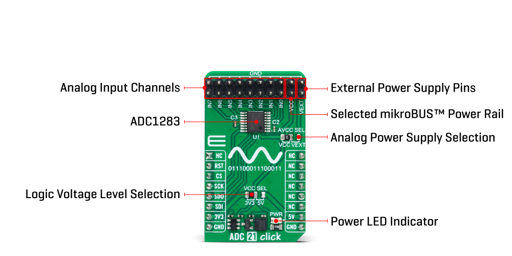
This Click board™ can operate with either 3.3V or 5V logic voltage levels selected via the VCC SEL jumper. This way, it is allowed for both 3.3V and 5V capable MCUs to use the communication lines properly. Additionally, there is a possibility for the ADC1283 analogue power supply selection via jumper labelled AVCC SEL to supply the ADC1283 from an external power supply in the range from 2.7V to 5.5V or with mikroBUS™ power rails. However, the ADC 21 Click Board™ comes equipped with a library containing easy-to-use functions and an example code that can be used, as a reference, for further development.
| Type | ADC |
| Applications | It can be used for the most demanding applications, from general-purpose remote data acquisition and instrumentation to industrial applications |
| On-board modules | ADC1283 - eight-channel analog-to-digital converter from STMicroelectronics |
| Key Features | Low power consumption, high accuracy, high-speed serial interface, high performance, selectable conversion rate, 12-bit SAR-based ADC, selectable analogue power supply, and more |
| Interface | SPI |
| Compatibility | mikroBUS |
| Click board size | M (42.9 x 25.4 mm) |
| Input Voltage | 3.3V or 5V |
This table shows how the pinout of the ADC 21 Click Board™ corresponds to the pinout on the mikroBUS™ socket (the latter shown in the two middle columns).
| Notes | Pin | Pin | Notes | ||||
|---|---|---|---|---|---|---|---|
| NC | 1 | AN | PWM | 16 | NC | ||
| NC | 2 | RST | INT | 15 | NC | ||
| SPI Chip Select | CS | 3 | CS | RX | 14 | NC | |
| SPI Clock | SCK | 4 | SCK | TX | 13 | NC | |
| SPI Data OUT | SDO | 5 | MISO | SCL | 12 | NC | |
| SPI Data IN | SDI | 6 | MOSI | SDA | 11 | NC | |
| Power Supply | 3.3V | 7 | 3.3V | 5V | 10 | 5V | Power Supply |
| Ground | GND | 8 | GND | GND | 9 | GND | Ground |
| Label | Name | Default | Description |
|---|---|---|---|
| LD1 | PWR | - | Power LED Indicator |
| JP1 | VCC SEL | Left | Logic Level Voltage Selection 3V3/5V: Left position 3V3, Right position 5V |
| JP2 | AVCC SEL | Left | Analog Power Supply Selection VCC/VEXT: Left position VCC, Right position VEXT |
| J1 | - | Populated | Analog Input Channels Header |
| Description | Min | Typ | Max | Unit |
|---|---|---|---|---|
| Supply Voltage | 3.3 | - | 5 | V |
| Analog Power Supply Voltage | 2.7 | - | 5.5 | V |
| Resolution | - | 12 | - | bits |
| Data Rate | 50 | - | 200 | ksps |
We provide a library for the ADC 21 Click Board™ as well as a demo application (example), developed using MikroE compilers. The demo can run on all the main MikroE development boards.
The package can be downloaded/installed directly from NECTO Studio The package Manager (recommended), downloaded from our LibStock™ or found on MikroE Github account.
Library Description
This library contains API for the ADC 21 Click Board™ driver.
Key functions
adc21_read_raw_adc This function reads raw ADC value from the selected channel by using SPI serial interface.
adc21_read_voltage This function reads raw ADC value from the selected channel and converts it to a proportional voltage level depending on the avcc selection.
Example Description
This example demonstrates the use of the ADC 21 Click Board™ by reading and displaying the voltage levels from 8 analogue input channels.
void application_task ( void )
 {
     static uint8_t ch_num = ADC21_CHANNEL_0;
     float ch_voltage;
     if ( ADC21_OK == adc21_read_voltage ( &adc21, ch_num, ADC21_AVCC_3V3, &ch_voltage ) )
     {
         log_printf ( &logger, " CH%u voltage: %.2f Vrn", ( uint16_t ) ch_num, ch_voltage );
     }
     if ( ++ch_num > ADC21_CHANNEL_7 )
     {
         log_printf ( &logger, " ------------------------rnn" );
         ch_num = ADC21_CHANNEL_0;
         Delay_ms ( 1000 );
     }
 }
The full application code, and ready to use projects can be installed directly from NECTO Studio The package Manager (recommended), downloaded from our LibStock™ or found on MikroE Github account.
Other MikroE Libraries used in the example:
Additional Notes and Information
Depending on the development board you are using, you may need USB UART Click Board™, USB UART 2 Click or RS232 Click to connect to your PC, for development systems with no UART to USB interface available on the board. UART terminal is available in all MikroE compilers.
The ADC 21 Click Board™ is supported with mikroSDK - MikroE Software Development Kit, that needs to be downloaded from the LibStock and installed for the compiler you are using to ensure proper operation of mikroSDK compliant Click board™ demo applications.
- manufacturer: Mikroelektronika d.o.o. - warranty: 12 months - backorder_label: If no stock shown above, check availability - attachments: [{"download_file":[{"download_file":"ADC 21 Click Board™ Schematic"}],"download_filetype":[{"download_filetype":"pdf"}]},{"download_file":[{"download_file":"STMicrosystems ADC1283 ADC Datasheet"}],"download_filetype":[{"download_filetype":"pdf"}]}] - device_vendor: STMicroelectronics - device_type: ADC1283IPT - warranty: 12 months - brand: MikroE - condition: new - manufacturer: Mikroelektronika d.o.o. - target_keyword: ADC 21 Click Board - brands: gid://shopify/Metaobject/56256004319 - breadcrumbs: ["gid://shopify/Collection/447955239135","gid://shopify/Collection/241680580797","gid://shopify/Collection/241545314493"] - mpn: MIKROE-5531 - customhs_code: 847330 - detailed_description: {"type":"root","children":[{"type":"heading","level":3,"children":[{"type":"text","value":"How Does The ADC 21 Click Board™ Work?"}]},{"type":"paragraph","children":[{"type":"text","value":"The ADC 21 Click Board™ is based on the ADC1283, a high-performance eight-channel analogue-to-digital converter from STMicroelectronics. The ADC1283 implements a successive approximation register (SAR) structure to convert analogue signals into 12-bit pure binary digital outputs. The conversion circuit includes a fast settling time comparator to convey instruction into the register to store digital 0 or 1 and a redistribution DAC with logic control to have the ADC compare the track signal with a reference signal at each clock cycle."}]},{"type":"paragraph","children":[{"type":"text","value":""}]},{"type":"paragraph","children":[{"type":"text","value":"The ADC 21 Click Board™ communicates with MCU through a standard SPI interface and operates at clock rates up to 3.2MHz, for all configurations and acquiring conversion results. The AD conversion is carried out in two phases. The sampling phase conveys the input signal through the capacitance array for the first three clock cycles. Then, the evaluation phase converts into a digital 12-bit signal within 13 clock cycles. At each clock cycle of the evaluation phase, the hold signal is compared with a new value distributed by the DAC, and the result is stored in the 12-bit register, with MSB first. A complete conversion requires 16 clock cycles to generate a new 12-bit word on the SDO pin on the mikroBUS™ socket."}]},{"type":"paragraph","children":[{"type":"text","value":"This Click board™ can operate with either 3.3V or 5V logic voltage levels selected via the VCC SEL jumper. This way, it is allowed for both 3.3V and 5V capable MCUs to use the communication lines properly. Additionally, there is a possibility for the ADC1283 analogue power supply selection via jumper labelled AVCC SEL to supply the ADC1283 from an external power supply in the range from 2.7V to 5.5V or with mikroBUS™ power rails. However, the ADC 21 Click Board™ comes equipped with a library containing easy-to-use functions and an example code that can be used, as a reference, for further development."}]},{"type":"heading","level":3,"children":[{"type":"text","value":"SPECIFICATIONS"}]},{"type":"paragraph","children":[{"type":"text","value":"Type\nADC\nApplications\nIt can be used for the most demanding applications, from general-purpose remote data acquisition and instrumentation to industrial applications\nOn-board modules\nADC1283 - eight-channel analog-to-digital converter from STMicroelectronics\nKey Features\nLow power consumption, high accuracy, high-speed serial interface, high performance, selectable conversion rate, 12-bit SAR-based ADC, selectable analogue power supply, and more\nInterface\nSPI\nCompatibility\nmikroBUS\nClick board size\nM (42.9 x 25.4 mm)\nInput Voltage\n3.3V or 5V"}]},{"type":"heading","level":3,"children":[{"type":"text","value":"PINOUT DIAGRAM"}]},{"type":"paragraph","children":[{"type":"text","value":"This table shows how the pinout of the ADC 21 Click Board™ corresponds to the pinout on the mikroBUS™ socket (the latter shown in the two middle columns)."}]},{"type":"paragraph","children":[{"type":"text","value":"Notes\nPin\nPin\nNotes\nNC\n1\nAN\nPWM\n16\nNC\nNC\n2\nRST\nINT\n15\nNC\nSPI Chip Select\nCS\n3\nCS\nRX\n14\nNC\nSPI Clock\nSCK\n4\nSCK\nTX\n13\nNC\nSPI Data OUT\nSDO\n5\nMISO\nSCL\n12\nNC\nSPI Data IN\nSDI\n6\nMOSI\nSDA\n11\nNC\nPower Supply\n3.3V\n7\n3.3V\n5V\n10\n5V\nPower Supply\nGround\nGND\n8\nGND\nGND\n9\nGND\nGround"}]},{"type":"heading","level":3,"children":[{"type":"text","value":"ONBOARD SETTINGS AND INDICATORS"}]},{"type":"paragraph","children":[{"type":"text","value":"Label\nName\nDefault\nDescription\nLD1\nPWR\n-\nPower LED Indicator\nJP1\nVCC SEL\nLeft\nLogic Level Voltage Selection 3V3/5V: Left position 3V3, Right position 5V\nJP2\nAVCC SEL\nLeft\nAnalog Power Supply Selection VCC/VEXT: Left position VCC, Right position VEXT\nJ1\n-\nPopulated\nAnalog Input Channels Header"}]},{"type":"heading","level":3,"children":[{"type":"text","value":"ADC 21 CLICK ELECTRICAL SPECIFICATIONS"}]},{"type":"paragraph","children":[{"type":"text","value":"Description\nMin\nTyp\nMax\nUnit\nSupply Voltage\n3.3\n-\n5\nV\nAnalog Power Supply Voltage\n2.7\n-\n5.5\nV\nResolution\n-\n12\n-\nbits\nData Rate\n50\n-\n200\nksps"}]}]} - summary:Upgrade your analogue to digital conversion with the ADC 21 Click Board™ - a compact add-on board that delivers high accuracy and reliable performance for the most demanding applications. Whether you need remote data acquisition or instrumentation for industrial applications, the ADC 21 Click Board™ is the perfect solution for you.
The ADC 21 Click Board™ features the ADC1283, a pure CMOS, eight-channel, 12-bit analogue-to-digital converter from STMicroelectronics. With a conversion rate of 50ksps to 200ksps, this low-power ADC delivers precise digital representation of analogue voltage. Its architecture is based on a successive approximation register with an internal track-and-hold cell, ensuring accurate and reliable performance.
With eight single-ended multiplexed inputs, the ADC 21 Click Board™ offers versatile input options. The output serial data is straight binary and SPI-compatible, making it easy to integrate with other systems.
The ADC 21 Click Board™ is supported by a mikroSDK-compliant library, which includes functions that simplify software development. This means you can get up and running quickly without the need for complex programming.
At Click Board™, we understand the importance of delivering reliable products. That's why the ADC 21 Click Board™ comes as a fully tested product, ready for use on any system equipped with the mikroBUS™ socket. You can trust that you're getting a high-quality product that will deliver accurate and reliable performance for all your analogue to digital conversion needs.