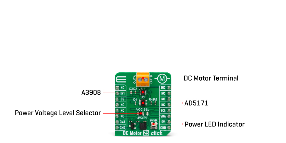
The DC Motor 25 Click Board™ is based on the A3908, a fully integrated low-voltage motor driver for DC motors from Allegro Microsystems. This Click board™ provides all the input and output capabilities necessary to drive DC motors (OUT terminal), alongside monitor diagnostic functions. The A3908 is rated for an operating voltage range compatible with both mikroBUS™ power rails and output currents up to 500mA, programmable via an external I2C-configurable digital potentiometer, the AD5171 from Analog Devices. The A3908 also has complete protection capabilities like thermal shutdown, undervoltage lockout, and crossover current (shoot-through) protection, allowing robust and reliable operation.
Logic pins labelled IN1 and IN2, routed on the default positions of RST and PWM pins of the mikroBUS socket, are provided to control the motor direction of rotation, brake, and standby modes. When both pins are in a high logic state, the A3908 goes into high-side brake mode, which turns on both source drivers. There is no protection during braking, so care must be taken to ensure that the peak current does not exceed the absolute maximum current.
Th DC Motor 25 Click Board™ can operate with either 3.3V or 5V logic voltage levels selected via the VCC SEL jumper. This way, both 3.3V and 5V capable MCUs can use the communication lines properly. However, the Click board™ comes equipped with a library containing easy-to-use functions and an example code that can be used, as a reference, for further development.
| Type | Brushed |
| Applications | It can be used for robotic actuators and pumps, battery-powered toys and games, low-noise instrumentation systems, and more |
| On-board modules | A3908 - bidirectional DC motor driver from Allegro Microsystems |
| Key Features | Adjustable output current up to 500mA, driver control via logic pins, additional operational modes, internal protection, wide operating voltage range, low power consumption, and more |
| Interface | GPIO, I2C |
| Compatibility | mikroBUS |
| Click board size | S (28.6 x 25.4 mm) |
| Input Voltage | 3.3V or 5V |
This table shows how the DC Motor 25 Click Board™ pinout corresponds to the pinout on the mikroBUS™ socket (the latter shown in the two middle columns).
| Notes | Pin | Pin | Notes | ||||
|---|---|---|---|---|---|---|---|
| NC | 1 | AN | PWM | 16 | IN2 | Driver Control 2 | |
| Driver Control 1 | IN1 | 2 | RST | INT | 15 | NC | |
| NC | 3 | CS | RX | 14 | NC | ||
| NC | 4 | SCK | TX | 13 | NC | ||
| NC | 5 | MISO | SCL | 12 | SCL | I2C Clock | |
| NC | 6 | MOSI | SDA | 11 | SDA | I2C Data | |
| Power Supply | 3.3V | 7 | 3.3V | 5V | 10 | 5V | Power Supply |
| Ground | GND | 8 | GND | GND | 9 | GND | Ground |
| Label | Name | Default | Description |
|---|---|---|---|
| LD1 | PWR | - | Power LED Indicator |
| JP1 | VCC SEL | Left | Power Voltage Level Selection 3V3/5V: Left position 3V3, Right position 5V |
| Description | Min | Typ | Max | Unit |
|---|---|---|---|---|
| Supply Voltage | 3.3 | - | 5 | V |
| Output Current | - | - | 500 | mA |
We provide a library for the DC Motor 25 Click Board™ and a demo application (example), developed using MIKROE compilers. The demo can run on all the main MIKROE development boards.
The package can be downloaded/installed directly from NECTO Studio The package Manager (recommended), downloaded from our LibStock™ or found on MikroE Github account.
Library Description
This library contains API for Dthe DC Motor 25 Click Board™ driver.
Key functions
dcmotor25_forward DC Motor 25 set forward mode function.
dcmotor25_reverse DC Motor 25 set reverse mode function.
dcmotor25_brake DC Motor 25 set brake mode function.
Example Description
This example demonstrates the use of the DC Motor 25 Click Board™ by driving the DC motor in both directions every 3 seconds.
void application_task ( void )
 {
     log_printf ( &logger, " Forwardrn" );
     dcmotor25_forward( &dcmotor25 );
     Delay_ms ( 3000 );

     log_printf ( &logger, " Brakern" );
     dcmotor25_brake( &dcmotor25 );
     Delay_ms ( 3000 );

     log_printf ( &logger, " Reversern" );
     dcmotor25_reverse( &dcmotor25 );
     Delay_ms ( 3000 );

     log_printf ( &logger, " Brakern" );
     dcmotor25_brake( &dcmotor25 );
     Delay_ms ( 3000 );
 }
The full application code, and ready-to-use projects can be installed directly from NECTO Studio. The package Manager (recommended), downloaded from our LibStock™ or found on the MikroE Github account.
Other MikroE Libraries used in the example:
Additional Notes and Information
Depending on the development board you are using, you may need USB UART Click Board™, USB UART 2 Click or RS232 Click to connect to your PC, for development systems with no UART to USB interface available on the board. UART terminal is available in all MIKROE compilers.
The DC Motor 25 Click Board™ is supported with mikroSDK - MikroE Software Development Kit, which needs to be downloaded from the LibStock and installed for the compiler you are using to ensure proper operation of mikroSDK compliant Click board™ demo applications.
- manufacturer: Mikroelektronika d.o.o. - warranty: 12 months - backorder_label: If no stock shown above, check availability - device_vendor: Allegro Microsystems - device_type: A3908 - attachments: [{"download_file":[{"download_file":"DC Motor 25 Click Board™ Schematic"}],"download_filetype":[{"download_filetype":"pdf"}]},{"download_file":[{"download_file":"Allegro MIcrosystems A3908 DC Motor Driver Datasheet"}],"download_filetype":[{"download_filetype":"pdf"}]}] - warranty: 12 months - brand: MikroE - manufacturer: Mikroelektronika d.o.o. - target_keyword: DC Motor 25 Click Board - brands: gid://shopify/Metaobject/56256004319 - breadcrumbs: ["gid://shopify/Collection/447955239135","gid://shopify/Collection/241680580797","gid://shopify/Collection/241545248957","gid://shopify/Collection/279405134013"] - mpn: MIKROE-5523 - customhs_code: 847330 - detailed_description: {"type":"root","children":[{"type":"heading","level":3,"children":[{"type":"text","value":"How Does The DC Motor 25 Click Board™ Work?"}]},{"type":"paragraph","children":[{"type":"text","value":"The DC Motor 25 Click Board™ is based on the A3908, a fully integrated low-voltage motor driver for DC motors from Allegro Microsystems. This Click board™ provides all the input and output capabilities necessary to drive DC motors (OUT terminal), alongside monitor diagnostic functions. The A3908 is rated for an operating voltage range compatible with both mikroBUS™ power rails and output currents up to 500mA, programmable via an external I2C-configurable digital potentiometer, the AD5171 from Analog Devices. The A3908 also has complete protection capabilities like thermal shutdown, undervoltage lockout, and crossover current (shoot-through) protection, allowing robust and reliable operation."}]},{"type":"paragraph","children":[{"type":"text","value":""}]},{"type":"paragraph","children":[{"type":"text","value":"Logic pins labelled IN1 and IN2, routed on the default positions of RST and PWM pins of the mikroBUS socket, are provided to control the motor direction of rotation, brake, and standby modes. When both pins are in a high logic state, the A3908 goes into high-side brake mode, which turns on both source drivers. There is no protection during braking, so care must be taken to ensure that the peak current does not exceed the absolute maximum current."}]},{"type":"paragraph","children":[{"type":"text","value":"Th DC Motor 25 Click Board™ can operate with either 3.3V or 5V logic voltage levels selected via the VCC SEL jumper. This way, both 3.3V and 5V capable MCUs can use the communication lines properly. However, the Click board™ comes equipped with a library containing easy-to-use functions and an example code that can be used, as a reference, for further development."}]},{"type":"heading","level":3,"children":[{"type":"text","value":"SPECIFICATIONS"}]},{"type":"paragraph","children":[{"type":"text","value":"Type\nBrushed\nApplications\nIt can be used for robotic actuators and pumps, battery-powered toys and games, low-noise instrumentation systems, and more\nOn-board modules\nA3908 - bidirectional DC motor driver from Allegro Microsystems\nKey Features\nAdjustable output current up to 500mA, driver control via logic pins, additional operational modes, internal protection, wide operating voltage range, low power consumption, and more\nInterface\nGPIO, I2C\nCompatibility\nmikroBUS\nClick board size\nS (28.6 x 25.4 mm)\nInput Voltage\n3.3V or 5V"}]},{"type":"heading","level":3,"children":[{"type":"text","value":"PINOUT DIAGRAM"}]},{"type":"paragraph","children":[{"type":"text","value":"This table shows how the DC Motor 25 Click Board™ pinout corresponds to the pinout on the mikroBUS™ socket (the latter shown in the two middle columns)."}]},{"type":"paragraph","children":[{"type":"text","value":"Notes\nPin\nPin\nNotes\nNC\n1\nAN\nPWM\n16\nIN2\nDriver Control 2\nDriver Control 1\nIN1\n2\nRST\nINT\n15\nNC\nNC\n3\nCS\nRX\n14\nNC\nNC\n4\nSCK\nTX\n13\nNC\nNC\n5\nMISO\nSCL\n12\nSCL\nI2C Clock\nNC\n6\nMOSI\nSDA\n11\nSDA\nI2C Data\nPower Supply\n3.3V\n7\n3.3V\n5V\n10\n5V\nPower Supply\nGround\nGND\n8\nGND\nGND\n9\nGND\nGround"}]},{"type":"heading","level":3,"children":[{"type":"text","value":"ONBOARD SETTINGS AND INDICATORS"}]},{"type":"paragraph","children":[{"type":"text","value":"Label\nName\nDefault\nDescription\nLD1\nPWR\n-\nPower LED Indicator\nJP1\nVCC SEL\nLeft\nPower Voltage Level Selection 3V3/5V: Left position 3V3, Right position 5V"}]},{"type":"heading","level":3,"children":[{"type":"text","value":"DC MOTOR 25 CLICK ELECTRICAL SPECIFICATIONS"}]},{"type":"paragraph","children":[{"type":"text","value":"Description\nMin\nTyp\nMax\nUnit\nSupply Voltage\n3.3\n-\n5\nV\nOutput Current\n-\n-\n500\nmA"}]},{"type":"heading","level":3,"children":[{"type":"text","value":" "}]}]} - summary:Unlock the full potential of your brushed DC motors with the all-new DC Motor 25 Click Board™! This compact add-on board is designed to deliver outstanding performance and versatility, thanks to the cutting-edge A3908 low-voltage bidirectional DC motor driver from Allegro Microsystems.
With an operating voltage range fully compatible with mikroBUS™ power rails and able to handle output currents of up to 500mA, the DC Motor 25 Click Board™ is perfect for a wide range of applications. Its unique output full-bridge incorporates source-side linear operation, ensuring a constant voltage across the motor coil for maximum efficiency.
Logic input pins are at your disposal for precise control over the motor's direction of rotation, brake, and standby modes. This means you can easily fine-tune your device's performance to fit your specific needs, whether it's robotic actuators, pumps, battery-powered toys and games, low-noise instrumentation systems, or any other application that requires a reliable DC motor driver.
The DC Motor 25 Click Board™ comes equipped with comprehensive protection features, ensuring robust and reliable operation in even the most demanding environments. Keep your devices running smoothly and safely, no matter the challenge.
Thanks to its mikroSDK-compliant library, the DC Motor 25 Click Board™ streamlines software development by providing you with various helpful functions. This means you can spend less time coding and more time enjoying your newly enhanced devices!
Designed for immediate use on a system equipped with a mikroBUS™ socket, the DC Motor 25 Click Board™ comes as a fully tested product. Get ready to experience the future of brushed DC motor drivers today!