The I2C MUX 6 Click Board™ as its foundation uses the PCA9518, an expandable four-channel bidirectional buffer controllable through the I2C serial interface from Texas Instruments. The primary SCL/SDA signal pair is directed to four channels where only one SCL/SDA channel can be selected at a time, determined on the state of the four Enable pins, routed to the AN, RST, CS, and PWM pins of the mikroBUS™ socket. The PCA9518 overcomes the restriction of maximum bus capacitance by separating and buffering the I2C data (SDA) and clock (SCL) lines into multiple groups of 400pF I2C channels.
The PCA9518 has several multi-directional open-drain buffers designed to support the standard low-level-contention arbitration of the I2C bus. Except during arbitration, the PCA9518 acts like a pair of non-inverting open-drain buffers, one for SDA and one for SCL. It can communicate with other PCA9518 hubs through a 4-wire inter-hub expansion bus, located on the onboard header with EXP labelled pins, i.e., permits extension of the I2C-bus by buffering both the data (SDA) and the clock (SCL) lines enabling virtually an unlimited number of buses of 400pF.
The PCA9518 communicates with MCU using the standard I2C interface that supports Standard-Mode (100 kHz) and Fast-Mode (400 kHz) operation. As mentioned before, each Enable pin, ENx, controls its associated SDAx and SCLx channels. When the ENx pin is in a low logic state, it isolates its corresponding SDAx and SCLx lines from the system by blocking the inputs from SDAx and SCLx and disabling the output drivers on these lines. It is essential that the ENx change state only when both the global bus and the local port are in an IDLE state to prevent system failures.
The I2C MUX 6 Click Board™is designed for 3.3V operation. It also has onboard terminals labelled as VCC-I2C to supply a voltage, 3.3V or 5V, for PCA9518's I2C lines, which are 5V-tolerant. However, the board must perform appropriate logic voltage level conversion before using MCUs with different logic levels. The Click board™ comes equipped with a library containing functions and an example code that can be used, as a reference, for further development.
| Type | I2C |
| Applications | Can be used for various applications from industrial to medical, communications, and automotive systems |
| On-board modules | PCA9518 - four-channel bidirectional buffer controllable through the I2C serial interface from Texas Instruments |
| Key Features | Low power consumption, fast I2C interface, 5V tolerant I2C and enable pins to support mixed-mode signal operation, powered-off high-impedance I2C pins, expansion bus, and more |
| Interface | I2C |
| Compatibility | mikroBUS |
| Click board size | M (42.9 x 25.4 mm) |
| Input Voltage | 3.3V |
This table shows how the pinout of the I2C MUX 6 Click Board™ corresponds to the pinout on the mikroBUS™ socket (the latter shown in the two middle columns).
| Notes | Pin | Pin | Notes | ||||
|---|---|---|---|---|---|---|---|
| Channel 1 Enable | EN1 | 1 | AN | PWM | 16 | EN4 | Channel 4 Enable |
| Channel 2 Enable | EN2 | 2 | RST | INT | 15 | NC | |
| Channel 3 Enable | EN3 | 3 | CS | RX | 14 | NC | |
| NC | 4 | SCK | TX | 13 | NC | ||
| NC | 5 | MISO | SCL | 12 | SCL | I2C Clock | |
| NC | 6 | MOSI | SDA | 11 | SDA | I2C Data | |
| Power Supply | 3.3V | 7 | 3.3V | 5V | 10 | NC | |
| Ground | GND | 8 | GND | GND | 9 | GND | Ground |
| Label | Name | Default | Description |
|---|---|---|---|
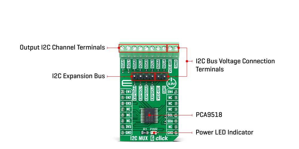
| LD1 | PWR | - | Power LED Indicator |
| J1 | - | Populated | I2C Expansion Header |
| Description | Min | Typ | Max | Unit |
|---|---|---|---|---|
| Supply Voltage | - | 3.3 | - | V |
| I2C Bus Voltage Range VCC-I2C | 3.3 | - | 5 | V |
| Operating Temperature Range | -40 | +25 | +85 | °C |
We provide a library for the I2C MUX 6 Click Board™ as well as a demo application (example), developed using MikroElektronika compilers. The demo can run on all the main MikroElektronika development boards.
The package can be downloaded/installed directly from NECTO Studio The package Manager (recommended), downloaded from our LibStock™ or found on MikroE Github account.
This library contains API for the I2C MUX 6 Click Board™ driver.
Key functions
i2cmux6_set_channel This function sets the desired channel active and configures its slave address.
i2cmux6_generic_write This function writes a desired number of data bytes starting from the selected register by using I2C serial interface.
i2cmux6_generic_read This function reads a desired number of data bytes starting from the selected register by using I2C serial interface.
This example demonstrates the use of the I2C MUX 6 Click Board™ by reading the device ID of a 6DOF IMU 11 and Compass 3 Click boards™ connected to the channels 1 and 4 respectively.
void application_task ( void )
 {
     uint8_t device_id;
     if ( I2CMUX6_OK == i2cmux6_set_channel ( &i2cmux6, DEVICE0_POSITION, DEVICE0_SLAVE_ADDRESS ) )
     {
         log_printf( &logger, "rn Active Channel: - " );
         for ( uint8_t cnt = 0; cnt < 4; cnt++ )
         {
             if ( ( DEVICE0_POSITION ) & ( 1 << cnt ) )
             {
                 log_printf( &logger, "%u - ", ( uint16_t ) ( cnt + 1 ) );
             }
         }
         if ( I2CMUX6_OK == i2cmux6_generic_read ( &i2cmux6, DEVICE0_REG_ID, &device_id, 1 ) )
         {
             log_printf( &logger, "rn %s - Device ID: 0x%.2Xrn", ( char * ) DEVICE0_NAME, ( uint16_t ) device_id );
         }
         Delay_ms( 1000 );
     }
     if ( I2CMUX6_OK == i2cmux6_set_channel ( &i2cmux6, DEVICE1_POSITION, DEVICE1_SLAVE_ADDRESS ) )
     {
         log_printf( &logger, "rn Active Channel: - " );
         for ( uint8_t cnt = 0; cnt < 4; cnt++ )
         {
             if ( ( DEVICE1_POSITION ) & ( 1 << cnt ) )
             {
                 log_printf( &logger, "%u - ", ( uint16_t ) ( cnt + 1 ) );
             }
         }
         if ( I2CMUX6_OK == i2cmux6_generic_read ( &i2cmux6, DEVICE1_REG_ID, &device_id, 1 ) )
         {
             log_printf( &logger, "rn %s - Device ID: 0x%.2Xrn", ( char * ) DEVICE1_NAME, ( uint16_t ) device_id );
         }
         Delay_ms( 1000 );
     }
 }
The full application code, and ready to use projects can be installed directly from NECTO Studio The package Manager (recommended), downloaded from our LibStock™ or found on MikroE Github account.
Other MikroE Libraries used in the example:
Depending on the development board you are using, you may need USB UART Click Board™, USB UART 2 Click or RS232 Click to connect to your PC, for development systems with no UART to USB interface available on the board. UART terminal is available in all MikroElektronika compilers.
The I2C MUX 6 Click Board™ is supported with mikroSDK - MikroElektronika Software Development Kit. To ensure proper operation of mikroSDK compliant Click board™ demo applications, mikroSDK should be downloaded from the LibStock and installed for the compiler you are using.
- mpn: MIKROE-5168 - condition: new - custom_product: false - mpn: MIKROE-5168 - google_product_category: Electronics - key_feature_2: Low power consumption, fast I2C interface, 5V tolerant I2C and enable pins to support mixed-mode signal operation, powered-off high-impedance I2C pins, expansion bus, and more - key_feature_3: Based on the PCA9518 - four-channel bidirectional buffer controllable through the I2C serial interface from Texas Instruments - key_feature_4: Can be used for various applications from industrial to medical, communications, and automotive systems - key_feature_5: mikroBUS: I2C Interface - device_vendor: Texas Instruments - device_type: PCA9518PWR - warranty: 12 months - brand: MikroE - manufacturer: Mikroelektronika d.o.o. - target_keyword: I2C MUX 6 Click Board - brands: gid://shopify/Metaobject/56256004319 - breadcrumbs: ["gid://shopify/Collection/447955239135","gid://shopify/Collection/241680580797","gid://shopify/Collection/241546100925"] - customhs_code: 847330 - detailed_description: {"type":"root","children":[{"type":"heading","level":3,"children":[{"type":"text","value":"How Does The I2C MUX 6 Click Board™Work?"}]},{"type":"paragraph","children":[{"type":"text","value":"The "},{"type":"text","value":"I2C MUX 6 Click Board™","bold":true,"italic":true},{"type":"text","value":" as its foundation uses the PCA9518, an expandable four-channel bidirectional buffer controllable through the I2C serial interface from Texas Instruments. The primary SCL/SDA signal pair is directed to four channels where only one SCL/SDA channel can be selected at a time, determined on the state of the four Enable pins, routed to the AN, RST, CS, and PWM pins of the mikroBUS™ socket. The PCA9518 overcomes the restriction of maximum bus capacitance by separating and buffering the I2C data (SDA) and clock (SCL) lines into multiple groups of 400pF I2C channels."}]},{"type":"paragraph","children":[{"type":"text","value":""}]},{"type":"paragraph","children":[{"type":"text","value":"The PCA9518 has several multi-directional open-drain buffers designed to support the standard low-level-contention arbitration of the I2C bus. Except during arbitration, the PCA9518 acts like a pair of non-inverting open-drain buffers, one for SDA and one for SCL. It can communicate with other PCA9518 hubs through a 4-wire inter-hub expansion bus, located on the onboard header with EXP labelled pins, i.e., permits extension of the I2C-bus by buffering both the data (SDA) and the clock (SCL) lines enabling virtually an unlimited number of buses of 400pF."}]},{"type":"paragraph","children":[{"type":"text","value":"The PCA9518 communicates with MCU using the standard I2C interface that supports Standard-Mode (100 kHz) and Fast-Mode (400 kHz) operation. As mentioned before, each Enable pin, ENx, controls its associated SDAx and SCLx channels. When the ENx pin is in a low logic state, it isolates its corresponding SDAx and SCLx lines from the system by blocking the inputs from SDAx and SCLx and disabling the output drivers on these lines. It is essential that the ENx change state only when both the global bus and the local port are in an IDLE state to prevent system failures."}]},{"type":"paragraph","children":[{"type":"text","value":"The "},{"type":"text","value":"I2C MUX 6 Click Board™","bold":true},{"type":"text","value":"is designed for 3.3V operation. It also has onboard terminals labelled as VCC-I2C to supply a voltage, 3.3V or 5V, for PCA9518's I2C lines, which are 5V-tolerant. However, the board must perform appropriate logic voltage level conversion before using MCUs with different logic levels. The Click board™ comes equipped with a library containing functions and an example code that can be used, as a reference, for further development."}]},{"type":"heading","level":3,"children":[{"type":"text","value":"SPECIFICATIONS"}]},{"type":"paragraph","children":[{"type":"text","value":"Type\nI2C\nApplications\nCan be used for various applications from industrial to medical, communications, and automotive systems\nOn-board modules\nPCA9518 - four-channel bidirectional buffer controllable through the I2C serial interface from Texas Instruments\nKey Features\nLow power consumption, fast I2C interface, 5V tolerant I2C and enable pins to support mixed-mode signal operation, powered-off high-impedance I2C pins, expansion bus, and more\nInterface\nI2C\nCompatibility\nmikroBUS\nClick board size\nM (42.9 x 25.4 mm)\nInput Voltage\n3.3V"}]},{"type":"heading","level":3,"children":[{"type":"text","value":"PINOUT DIAGRAM"}]},{"type":"paragraph","children":[{"type":"text","value":"This table shows how the pinout of the "},{"type":"text","value":"I2C MUX 6 Click Board™","bold":true},{"type":"text","value":" corresponds to the pinout on the mikroBUS™ socket (the latter shown in the two middle columns)."}]},{"type":"paragraph","children":[{"type":"text","value":"Notes\nPin\nPin\nNotes\nChannel 1 Enable\nEN1\n1\nAN\nPWM\n16\nEN4\nChannel 4 Enable\nChannel 2 Enable\nEN2\n2\nRST\nINT\n15\nNC\nChannel 3 Enable\nEN3\n3\nCS\nRX\n14\nNC\nNC\n4\nSCK\nTX\n13\nNC\nNC\n5\nMISO\nSCL\n12\nSCL\nI2C Clock\nNC\n6\nMOSI\nSDA\n11\nSDA\nI2C Data\nPower Supply\n3.3V\n7\n3.3V\n5V\n10\nNC\nGround\nGND\n8\nGND\nGND\n9\nGND\nGround"}]},{"type":"heading","level":3,"children":[{"type":"text","value":"ONBOARD SETTINGS AND INDICATORS"}]},{"type":"paragraph","children":[{"type":"text","value":"Label\nName\nDefault\nDescription\nLD1\nPWR\n-\nPower LED Indicator\nJ1\n-\nPopulated\nI2C Expansion Header"}]},{"type":"heading","level":3,"children":[{"type":"text","value":"I2C MUX 6 CLICK ELECTRICAL SPECIFICATIONS"}]},{"type":"paragraph","children":[{"type":"text","value":"Description\nMin\nTyp\nMax\nUnit\nSupply Voltage\n-\n3.3\n-\nV\nI2C Bus Voltage Range VCC-I2C\n3.3\n-\n5\nV\nOperating Temperature Range\n-40\n+25\n+85\n°C"}]},{"type":"heading","level":3,"children":[{"type":"text","value":" "}]}]} - summary:The I2C MUX 6 Click Board™ is a compact add-on board representing a bidirectional selector dedicated to I2C slave address conflicts applications. This board features the PCA9518, an expandable five-channel bidirectional buffer controlled by the I2C-bus from Texas Instruments. The PCA9518 overcomes the restriction of maximum bus capacitance by separating and buffering the I2C data (SDA) and clock (SCL) lines into multiple groups of 400pF I2C channels. It activates the desired channel via a given Enable pin and permits extension of the I2C-bus, through an onboard expansion header, by buffering both the data (SDA) and the clock (SCL) lines enabling virtually an unlimited number of buses of 400pF. This Click board™ is suitable for various industrial, medical, communications, and automotive applications.
The I2C MUX 6 Click Board™ is supported by a mikroSDK compliant library, which includes functions that simplify software development. This Click board™ comes as a fully tested product, ready to be used on a system equipped with the mikroBUS™ socket.