The Charger 18 Click Board™ as its foundation uses the LTC3553, a micropower multifunction power management integrated circuit (PMIC) for portable Li-Ion/Polymer battery-based applications from Analog Devices. It combines a USB-compatible PowerPath manager with automatic load prioritization delivering up to 400mA battery charge current from a 5V USB input. The device's 'instant-on' operation ensures immediate system load power when a USB supply is available, even with a fully discharged battery. Alongside a stand-alone battery charger, it also has a high-efficiency synchronous 200mA buck regulator and a 150mA low dropout linear regulator available on the present onboard connectors.
The Charger 18 Click Board™ has an input current limit selection allowing the user to select between 100mA and 500mA input current limit. The choice can be made by positioning the SMD jumper labelled as ISET SEL to an appropriate position. Besides ISET, it also possesses SEQ SEL jumper selection determining which regulator is enabled before the other. The first-regulator power-up selection is made by positioning this SMD jumper to an appropriate position marked as BUCK or LDO.
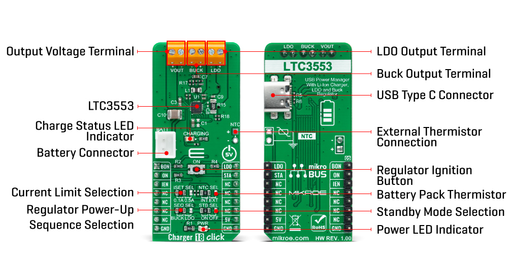
On the other hand, the BON and LDO pins routed to the AN and PWM pins on the mikroBUS™ socket enable the buck and LDO regulators by setting these pins to a high logic state. Alongside these pins, the LTC3553 also includes a pushbutton input to control the two regulators and system reset - an onboard pushbutton labelled ON, also routed to the RST pin on the mikroBUS™, representing the Regulator Ignition button. Pressing the button causes an STA interrupt, informing the MCU that this event has occurred.
These regulators are also related to a Standby Mode, selectable through an SMD jumper labelled as ISET SEL. When this jumper is placed ON, the buck and the LDO regulator quiescent current are reduced to low levels while maintaining output voltage regulation. The buck regulator is limited to a 10mA maximum load current in this mode, and the LDO regulator's response to line and load transients is slower.
As already mentioned in the text, the Charger 18 Click Board™ communicates with MCU using several GPIO pins. With the IEN pin routed to the CS pin on the mikroBUS™ socket is pulled high, the LTC3553 enters Suspend mode to comply with the USB specification. In this mode, the power path between USB and VOUT is put in a high impedance state to reduce the USB input current. This Click board™ also comes with a blue LED labelled as CHARGING for battery charging state.
An NTC function is also available for temperature-qualified charging. The temperature monitoring feature is selectable via jumper labelled as NTC SEL, where the user can choose between external or internal modes of monitoring. A negative temperature coefficient (NTC) thermistor input for the battery temperature monitor is provided for external mode.
The Charger 18 Click Board™ can be operated only with a 5V logic voltage level. The board must perform appropriate logic voltage level conversion before using MCUs with different logic levels. However, the Click board™ comes equipped with a library containing functions and an example code that can be used, as a reference, for further development.
| Type | Battery charger |
| Applications | The Charger 18 Click Board™ can be used as a Li-Ion/Polymer battery charger for portable devices and accessories, power tools, and more |
| On-board modules | LTC3553 - micropower, highly integrated power management, and battery charger for single-cell Li-Ion/Polymer battery applications from Analog Devices |
| Key Features | High efficiency, USB, integrated buck and LDO regulators, accuracy, programmable input current limit, battery charging indication, and more |
| Interface | GPIO |
| Compatibility | mikroBUS |
| Click board size | L (57.15 x 25.4 mm) |
| Input Voltage | 5V,External |
This table shows how the pinout of the Charger 18 Click Board™ corresponds to the pinout on the mikroBUS™ socket (the latter shown in the two middle columns).
| Notes | Pin | Pin | Notes | ||||
|---|---|---|---|---|---|---|---|
| Buck Enable | BON | 1 | AN | PWM | 16 | LDO | LDO Enable |
| Regulator Ignition | ON | 2 | RST | INT | 15 | STA | Pushbutton Status |
| Suspend Mode | IEN | 3 | CS | RX | 14 | NC | |
| NC | 4 | SCK | TX | 13 | NC | ||
| NC | 5 | MISO | SCL | 12 | NC | ||
| NC | 6 | MOSI | SDA | 11 | NC | ||
| NC | 7 | 3.3V | 5V | 10 | 5V | Power Supply | |
| Ground | GND | 8 | GND | GND | 9 | GND | Ground |
| Label | Name | Default | Description |
|---|---|---|---|
| LD1 | PWR | - | Power LED Indicator |
| LD2 | CHARGING | - | Charge Status LED Indicator |
| JP1 | ISET SEL | Left | Current Limit Selection 0.1A/0.5A: Left position 0.1A, Right position 0.5A |
| JP2 | SEQ SEL | Left | Regulator Power-Up Sequence Selection BUCK/LDO: Left position BUCK, Right position LDO |
| JP3 | STB SEL | Left | Standby Mode Selection ON/OFF: Left position ON, Right position OFF |
| JP4 | NTC SEL | Left | Battery Pack Thermistor Selection INT/EXT: Left position INT, Right position EXT |
| T1 | ON | - | Regulator Ignition Button |
| J1 | NTC | Unpopulated | External Thermistor Connection Header |
| Description | Min | Typ | Max | Unit |
|---|---|---|---|---|
| Supply Voltage | - | 5 | - | V |
| Charge Output Current | - | 400 | - | mA |
| Buck Regulator Output Current | - | 200 | - | mA |
| LDO Output Current | - | 150 | - | mA |
| Operating Temperature Range | -40 | +25 | +85 | °C |
We provide a library for the Charger 18 Click Board™ as well as a demo application (example), developed using MikroElektronika compilers. The demo can run on all the main MikroElektronika development boards.
The package can be downloaded/installed directly from NECTO Studio The package Manager (recommended), downloaded from our LibStock™ or found on MikroE Github account.
This library contains API for the Charger 18 Click Board™ driver.
Key functions
charger18_buck_control This function controls the buck regulator enable state of Charger 18 click board.
charger18_ldo_control This function controls the low dropout (LDO) regulator enable state of Charger 18 click board.
charger18_suspend_control This function controls the suspend charging mode state of Charger 18 click board.
This example demonstrates the use of the Charger 18 Click Board™ by controlling the status of the charger as well as the LDO and BUCK regulators.
void application_task ( void )
 {
     charger18_suspend_control( &charger18, CHARGER18_CONTROL_DISABLE );
     log_printf( &logger, " CHARGER : ONrn" );
     Delay_ms( 10000 );
     charger18_suspend_control( &charger18, CHARGER18_CONTROL_ENABLE );
     log_printf( &logger, " CHARGER : OFFrn" );
     Delay_ms( 3000 );
     charger18_buck_control( &charger18, CHARGER18_CONTROL_ENABLE );
     log_printf( &logger, " BUCK    : ONrn" );
     Delay_ms( 3000 );
     charger18_buck_control( &charger18, CHARGER18_CONTROL_DISABLE );
     log_printf( &logger, " BUCK    : OFFrn" );
     Delay_ms( 3000 );
     charger18_ldo_control( &charger18, CHARGER18_CONTROL_ENABLE );
     log_printf( &logger, " LDO     : ONrn" );
     Delay_ms( 3000 );
     charger18_ldo_control( &charger18, CHARGER18_CONTROL_DISABLE );
     log_printf( &logger, " LDO     : OFFrnn" );
     Delay_ms( 3000 );
 }
The full application code, and ready to use projects can be installed directly from NECTO Studio The package Manager (recommended), downloaded from our LibStock™ or found on MikroE Github account.
Other MikroE Libraries used in the example:
Depending on the development board you are using, you may need USB UART click, USB UART 2 Click or RS232 Click to connect to your PC, for development systems with no UART to USB interface available on the board. UART terminal is available in all MikroElektronika compilers.
The Charger 18 Click Board™ is supported with mikroSDK - MikroElektronika Software Development Kit. To ensure proper operation of mikroSDK compliant Click board™ demo applications, mikroSDK should be downloaded from the LibStock and installed for the compiler you are using.
- manufacturer: Mikroelektronika d.o.o. - warranty: 12 months - backorder_label: If no stock shown above, check availability - attachments: [{"download_file":[{"download_file":"Charger 18 Click Board™ Schematic"}],"download_filetype":[{"download_filetype":"pdf"}]},{"download_file":[{"download_file":"Analog Devices LTC3553 Power Management/Charger Datasheet"}],"download_filetype":[{"download_filetype":"pdf"}]}] - feature_1: Based on the LTC3553 PMIC from Analog Devices - feature_2: Includes a PowerPath Manager - feature_3: Designed for USB Applications - mpn: MIKROE-4990 - mpn: MIKROE-4990 - custom_label_0: Click Board - google_product_category: Electronics - condition: new - custom_product: false - device_vendor: Analog Devices Inc. - device_type: LTC3553EUD#TRPBF - warranty: 12 months - brand: MikroE - manufacturer: Mikroelektronika d.o.o. - target_keyword: Charger 18 Click Board - brands: gid://shopify/Metaobject/56256004319 - breadcrumbs: ["gid://shopify/Collection/447955239135","gid://shopify/Collection/241680580797","gid://shopify/Collection/241545478333","gid://shopify/Collection/279697490109"] - customhs_code: 847330 - detailed_description: {"type":"root","children":[{"type":"heading","level":3,"children":[{"type":"text","value":"How Does The Charger 18 Click Board™ Work?"}]},{"type":"paragraph","children":[{"type":"text","value":"The "},{"type":"text","value":"Charger 18 Click Board™","bold":true,"italic":true},{"type":"text","value":" as its foundation uses the LTC3553, a micropower multifunction power management integrated circuit (PMIC) for portable Li-Ion/Polymer battery-based applications from Analog Devices. It combines a USB-compatible PowerPath manager with automatic load prioritization delivering up to 400mA battery charge current from a 5V USB input. The device's 'instant-on' operation ensures immediate system load power when a USB supply is available, even with a fully discharged battery. Alongside a stand-alone battery charger, it also has a high-efficiency synchronous 200mA buck regulator and a 150mA low dropout linear regulator available on the present onboard connectors."}]},{"type":"paragraph","children":[{"type":"text","value":""}]},{"type":"paragraph","children":[{"type":"text","value":"The "},{"type":"text","value":"Charger 18 Click Board™","bold":true},{"type":"text","value":" has an input current limit selection allowing the user to select between 100mA and 500mA input current limit. The choice can be made by positioning the SMD jumper labelled as ISET SEL to an appropriate position. Besides ISET, it also possesses SEQ SEL jumper selection determining which regulator is enabled before the other. The first-regulator power-up selection is made by positioning this SMD jumper to an appropriate position marked as BUCK or LDO."}]},{"type":"paragraph","children":[{"type":"text","value":"On the other hand, the BON and LDO pins routed to the AN and PWM pins on the mikroBUS™ socket enable the buck and LDO regulators by setting these pins to a high logic state. Alongside these pins, the LTC3553 also includes a pushbutton input to control the two regulators and system reset - an onboard pushbutton labelled ON, also routed to the RST pin on the mikroBUS™, representing the Regulator Ignition button. Pressing the button causes an STA interrupt, informing the MCU that this event has occurred."}]},{"type":"paragraph","children":[{"type":"text","value":"These regulators are also related to a Standby Mode, selectable through an SMD jumper labelled as ISET SEL. When this jumper is placed ON, the buck and the LDO regulator quiescent current are reduced to low levels while maintaining output voltage regulation. The buck regulator is limited to a 10mA maximum load current in this mode, and the LDO regulator's response to line and load transients is slower."}]},{"type":"paragraph","children":[{"type":"text","value":"As already mentioned in the text, the "},{"type":"text","value":"Charger 18 Click Board™ ","bold":true},{"type":"text","value":"communicates with MCU using several GPIO pins. With the IEN pin routed to the CS pin on the mikroBUS™ socket is pulled high, the LTC3553 enters Suspend mode to comply with the USB specification. In this mode, the power path between USB and VOUT is put in a high impedance state to reduce the USB input current. This Click board™ also comes with a blue LED labelled as CHARGING for battery charging state."}]},{"type":"paragraph","children":[{"type":"text","value":"An NTC function is also available for temperature-qualified charging. The temperature monitoring feature is selectable via jumper labelled as NTC SEL, where the user can choose between external or internal modes of monitoring. A negative temperature coefficient (NTC) thermistor input for the battery temperature monitor is provided for external mode."}]},{"type":"paragraph","children":[{"type":"text","value":"The "},{"type":"text","value":"Charger 18 Click Board™","bold":true},{"type":"text","value":" can be operated only with a 5V logic voltage level. The board must perform appropriate logic voltage level conversion before using MCUs with different logic levels. However, the Click board™ comes equipped with a library containing functions and an example code that can be used, as a reference, for further development."}]},{"type":"heading","level":3,"children":[{"type":"text","value":"SPECIFICATIONS"}]},{"type":"paragraph","children":[{"type":"text","value":"Type\nBattery charger\nApplications\nThe Charger 18 Click Board™ can be used as a Li-Ion/Polymer battery charger for portable devices and accessories, power tools, and more\nOn-board modules\nLTC3553 - micropower, highly integrated power management, and battery charger for single-cell Li-Ion/Polymer battery applications from Analog Devices\nKey Features\nHigh efficiency, USB, integrated buck and LDO regulators, accuracy, programmable input current limit, battery charging indication, and more\nInterface\nGPIO\nCompatibility\nmikroBUS\nClick board size\nL (57.15 x 25.4 mm)\nInput Voltage\n5V,External"}]},{"type":"heading","level":3,"children":[{"type":"text","value":"PINOUT DIAGRAM"}]},{"type":"paragraph","children":[{"type":"text","value":"This table shows how the pinout of the "},{"type":"text","value":"Charger 18 Click Board™","bold":true},{"type":"text","value":" corresponds to the pinout on the mikroBUS™ socket (the latter shown in the two middle columns)."}]},{"type":"paragraph","children":[{"type":"text","value":"Notes\nPin\nPin\nNotes\nBuck Enable\nBON\n1\nAN\nPWM\n16\nLDO\nLDO Enable\nRegulator Ignition\nON\n2\nRST\nINT\n15\nSTA\nPushbutton Status\nSuspend Mode\nIEN\n3\nCS\nRX\n14\nNC\nNC\n4\nSCK\nTX\n13\nNC\nNC\n5\nMISO\nSCL\n12\nNC\nNC\n6\nMOSI\nSDA\n11\nNC\nNC\n7\n3.3V\n5V\n10\n5V\nPower Supply\nGround\nGND\n8\nGND\nGND\n9\nGND\nGround"}]},{"type":"heading","level":3,"children":[{"type":"text","value":"ONBOARD SETTINGS AND INDICATORS"}]},{"type":"paragraph","children":[{"type":"text","value":"Label\nName\nDefault\nDescription\nLD1\nPWR\n-\nPower LED Indicator\nLD2\nCHARGING\n-\nCharge Status LED Indicator\nJP1\nISET SEL\nLeft\nCurrent Limit Selection 0.1A/0.5A: Left position 0.1A, Right position 0.5A\nJP2\nSEQ SEL\nLeft\nRegulator Power-Up Sequence Selection BUCK/LDO: Left position BUCK, Right position LDO\nJP3\nSTB SEL\nLeft\nStandby Mode Selection ON/OFF: Left position ON, Right position OFF\nJP4\nNTC SEL\nLeft\nBattery Pack Thermistor Selection INT/EXT: Left position INT, Right position EXT\nT1\nON\n-\nRegulator Ignition Button\nJ1\nNTC\nUnpopulated\nExternal Thermistor Connection Header"}]},{"type":"heading","level":3,"children":[{"type":"text","value":"CHARGER 18 CLICK ELECTRICAL SPECIFICATIONS"}]},{"type":"paragraph","children":[{"type":"text","value":"Description\nMin\nTyp\nMax\nUnit\nSupply Voltage\n-\n5\n-\nV\nCharge Output Current\n-\n400\n-\nmA\nBuck Regulator Output Current\n-\n200\n-\nmA\nLDO Output Current\n-\n150\n-\nmA\nOperating Temperature Range\n-40\n+25\n+85\n°C"}]},{"type":"heading","level":3,"children":[{"type":"text","value":" "}]}]} - summary:The Charger 18 Click Board™ is a compact add-on board representing a single-cell battery charger. This board features the LTC3553, a micropower, highly integrated power management, and battery charger for single-cell Li-Ion/Polymer battery applications from Analog Devices. Designed specifically for USB applications, it also includes a PowerPath manager with automatic load prioritization and input current limit, a battery charger, and numerous internal protection features. It also indicates a battery charge state, and it comes with a synchronous 200mA buck regulator and a 150mA low dropout linear regulator (LDO). This Click board™ is suitable as a Li-Ion/Polymer battery charger for portable devices and accessories, power tools, and more.
The Charger 18 Click Board™ is supported by a mikroSDK compliant library, which includes functions that simplify software development. This Click board™ comes as a fully tested product, ready to be used on a system equipped with the mikroBUS™ socket.