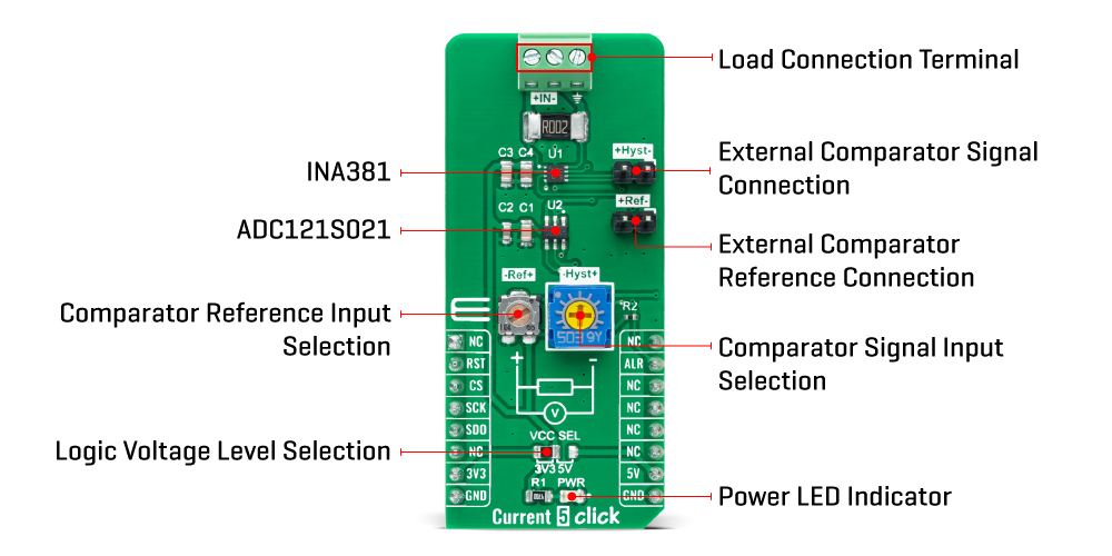
The Current 5 Click Board™ as its foundation uses the INA381, a zero-drift topology, a current-sensing amplifier with an integrated comparator that can be used in both low-side and high-side current-sensing and protection applications from Texas Instruments. This current-sensing amplifier accurately measures voltages developed across the current-sensing resistor (also known as current-shunt resistors) on common-mode voltages that far exceed the device supply voltage. Current is measured on IN load connection terminal withstanding the full common-mode voltages from –0.2V to +26V at the input pins when the supply voltage is removed without causing damage.
The INA381 also uses a reference input from an onboard REF potentiometer that simplifies setting the corresponding current threshold level to use for out-of-range comparison. Combining the precision measurement of the current-sense amplifier and the onboard comparator enables an all-in-one overcurrent detection device. This combination creates a highly-accurate design that quickly detects out-of-range conditions and allows the system to take corrective actions to prevent potential component or system-wide damage.
The amplified output voltage of the INA381 is developed across the onboard current-sensing resistor, which is the input voltage across the IN terminal (IN+ and IN– pins) multiplied by the gain of the amplifier (200V/V). The output voltage of the INA381 is then converted to a digital value using the ADC121S021, a low-power, single-channel 12-bit analog to digital converter (ADC), with a high-speed SPI interface also from Texas Instruments.
The INA381's integrated comparator is designed to quickly detect when the sense current is out-of-range, and provide an interrupt alert signal, routed to the INT pin of the mikroBUS™ socket, for quicker and faster responses. This alert output can be configured to operate in two modes, transparent or latched, selectable according to the logic state on the RST pin of the mikroBUS™ socket. In transparent mode, the output status follows the input state, while in the latched mode, the alert output is cleared only when the latch is reset.
The onboard comparator in the INA381 is designed to reduce the possibility of oscillations in the alert output when the measured signal level is near the over-limit threshold level due to noise, with a hysteresis 50mV. When the voltage on the comparator input exceeds the voltage developed at the comparator reference input, the alert signal sets to a low logic state. The output voltage then must drop to less than the reference input threshold voltage by the hysteresis level of 50mV so that the alert pin de-asserts and returns to the nominal high state. Also, this board allows the user to change the hysteresis from a preset value of 50mV via an onboard Hyst potentiometer. The user can also bring external signals such as REF and HYST on the eponymous onboard headers.
The Current 5 Click Board™ can operate with both 3.3V and 5V logic voltage levels selected via the VCC SEL jumper. This way, it is allowed for both 3.3V and 5V capable MCUs to use the communication lines properly. However, the Click board™ comes equipped with a library containing easy-to-use functions and an example code that can be used, as a reference, for further development.
| Type | Measurements |
| Applications | The Current 5 Click Board™ be used for applications such as test and measurement, load and power supplies monitoring, low-side phase motor control, and many more |
| On-board modules | INA381 - high-speed current-sense amplifier with an integrated comparator from Texas Instruments |
| Key Features | Common-mode input range: –0.2 V to +26 V, high-accuracy amplifier, integrated comparator, 200V/V amplifier gain, alert threshold selection, supports transparent and latching modes, and more |
| Interface | SPI |
| Compatibility | mikroBUS |
| Click board size | L (57.15 x 25.4 mm) |
| Input Voltage | 3.3V or 5V |
This table shows how the pinout of the Current 5 Click Board™ corresponds to the pinout on the mikroBUS™ socket (the latter shown in the two middle columns).
| Notes | Pin | Pin | Notes | ||||
|---|---|---|---|---|---|---|---|
| NC | 1 | AN | PWM | 16 | NC | ||
| Mode Selection | RST | 2 | RST | INT | 15 | ALR | Overlimit Alert |
| SPI Chip Select | CS | 3 | CS | RX | 14 | NC | |
| SPI Clock | SCK | 4 | SCK | TX | 13 | NC | |
| SPI Data OUT | SDO | 5 | MISO | SCL | 12 | NC | |
| NC | 6 | MOSI | SDA | 11 | NC | ||
| Power Supply | 3.3V | 7 | 3.3V | 5V | 10 | 5V | Power Supply |
| Ground | GND | 8 | GND | GND | 9 | GND | Ground |
| Label | Name | Default | Description |
|---|---|---|---|
| LD1 | PWR | - | Power LED Indicator |
| JP1 | VCC SEL | Left | Logic Level Voltage Selection 3V3/5V: Left position 3V3, Right position 5V |
| J1 | Hyst | Populated | External Comparator Signal Connection |
| J2 | Ref | Populated | External Comparator Reference Connection |
| VR1 | Ref | - | Comparator Reference Input Selection |
| VR2 | Hyst | - | Comparator Signal Input Selection |
| Description | Min | Typ | Max | Unit |
|---|---|---|---|---|
| Supply Voltage VCC | 3.3 | - | 4 | V |
| Common-Mode Input Voltage IN | -0.2 | - | 26 | V |
| Gain | - | 200 | - | V/V |
| Accuracy | - | - | ±1 | % |
| Operating Temperature Range | -40 | +25 | +125 | °C |
We provide a library for the Current 5 Click Board™ as well as a demo application (example), developed using MikroElektronika compilers. The demo can run on all the main MikroElektronika development boards.The package can be downloaded/installed directly from NECTO Studio The package Manager (recommended), downloaded from our LibStock™ or found on the
- examples:Mikroe Github account.
This library contains API for the Current 5 Click Board™ driver.
Key functions
current5_get_current Get current.
current5_get_adc Read raw adc value.
current5_get_alert Get alert pin state.
This example application showcases ability of the device to read raw adc data and calculate the current from it.
void application_task ( void )
{
float current = 0;
current5_get_current( ¤t5, ¤t );
log_printf( &logger, " > Current[ A ]: %.2frn", current );
log_printf( &logger, "*************************************************rn" );
Delay_ms( 300 );
}
The full application code, and ready to use projects can be installed directly from NECTO Studio The package Manager (recommended), downloaded from our LibStock™ or found on Mikroe Github account.
Other Mikroe Libraries used in the example:
Depending on the development board you are using, you may need a USB UART Click, USB UART 2 Click or RS232 Click to connect to your PC, for development systems with no UART to USB interface available on the board. UART terminal is available in all MikroElektronika compilers.
The Current 5 Click Board™ is supported with mikroSDK - MikroElektronika Software Development Kit. To ensure proper operation of mikroSDK compliant Click board™ demo applications, mikroSDK should be downloaded from the LibStock and installed for the compiler you are using.
- manufacturer: Mikroelektronika d.o.o. - warranty: 12 months - backorder_label: If no stock shown above, check availability - title_tag: MikroE Current 5 Click Board™ (MIKROE-4953) - description_tag: The Current 5 Click Board™ is a compact add-on board that provides a precise and accurate current sensing solution. This board features the INA381, a high-speed current-sense amplifier with an integrated comparator from Texas Instruments. Available from Debug Store UK. - attachments: [{"download_file":[{"download_file":"Current 5 Click Board™ Schematic"}],"download_filetype":[{"download_filetype":"pdf"}]},{"download_file":[{"download_file":"Texas Instruments ADC121S021 12-bit ADC Datasheet"}],"download_filetype":[{"download_filetype":"pdf"}]},{"download_file":[{"download_file":"Texas Instruments INA381 Curent Sense Amplifier Datasheet"}],"download_filetype":[{"download_filetype":"pdf"}]}] - condition: new - custom_product: false - mpn: MIKROE-4953 - google_product_category: Electronics - custom_label_0: Click Board - mpn: MIKROE-4953 - device_vendor: Texas Instruments - device_type: ADC121S021CIMF/NOPB, INA381A4IDSGT - warranty: 12 months - brand: MikroE - manufacturer: Mikroelektronika d.o.o. - target_keyword: Current 5 Click Board - brands: gid://shopify/Metaobject/56256004319 - breadcrumbs: ["gid://shopify/Collection/447955239135","gid://shopify/Collection/241680580797","gid://shopify/Collection/241545969853"] - customhs_code: 847330 - detailed_description: {"type":"root","children":[{"type":"heading","level":3,"children":[{"type":"text","value":"How Does The Current 5 Click Board™ Work?"}]},{"type":"paragraph","children":[{"type":"text","value":"The "},{"type":"text","value":"Current 5 Click Board™","bold":true,"italic":true},{"type":"text","value":" as its foundation uses the INA381, a zero-drift topology, a current-sensing amplifier with an integrated comparator that can be used in both low-side and high-side current-sensing and protection applications from Texas Instruments. This current-sensing amplifier accurately measures voltages developed across the current-sensing resistor (also known as current-shunt resistors) on common-mode voltages that far exceed the device supply voltage. Current is measured on IN load connection terminal withstanding the full common-mode voltages from –0.2V to +26V at the input pins when the supply voltage is removed without causing damage."}]},{"type":"paragraph","children":[{"type":"text","value":""}]},{"type":"paragraph","children":[{"type":"text","value":"The INA381 also uses a reference input from an onboard REF potentiometer that simplifies setting the corresponding current threshold level to use for out-of-range comparison. Combining the precision measurement of the current-sense amplifier and the onboard comparator enables an all-in-one overcurrent detection device. This combination creates a highly-accurate design that quickly detects out-of-range conditions and allows the system to take corrective actions to prevent potential component or system-wide damage."}]},{"type":"paragraph","children":[{"type":"text","value":"The amplified output voltage of the INA381 is developed across the onboard current-sensing resistor, which is the input voltage across the IN terminal (IN+ and IN– pins) multiplied by the gain of the amplifier (200V/V). The output voltage of the INA381 is then converted to a digital value using the ADC121S021, a low-power, single-channel 12-bit analog to digital converter (ADC), with a high-speed SPI interface also from Texas Instruments."}]},{"type":"paragraph","children":[{"type":"text","value":"The INA381's integrated comparator is designed to quickly detect when the sense current is out-of-range, and provide an interrupt alert signal, routed to the INT pin of the mikroBUS™ socket, for quicker and faster responses. This alert output can be configured to operate in two modes, transparent or latched, selectable according to the logic state on the RST pin of the mikroBUS™ socket. In transparent mode, the output status follows the input state, while in the latched mode, the alert output is cleared only when the latch is reset."}]},{"type":"paragraph","children":[{"type":"text","value":"The onboard comparator in the INA381 is designed to reduce the possibility of oscillations in the alert output when the measured signal level is near the over-limit threshold level due to noise, with a hysteresis 50mV. When the voltage on the comparator input exceeds the voltage developed at the comparator reference input, the alert signal sets to a low logic state. The output voltage then must drop to less than the reference input threshold voltage by the hysteresis level of 50mV so that the alert pin de-asserts and returns to the nominal high state. Also, this board allows the user to change the hysteresis from a preset value of 50mV via an onboard Hyst potentiometer. The user can also bring external signals such as REF and HYST on the eponymous onboard headers."}]},{"type":"paragraph","children":[{"type":"text","value":"The "},{"type":"text","value":"Current 5 Click Board™","bold":true},{"type":"text","value":" can operate with both 3.3V and 5V logic voltage levels selected via the VCC SEL jumper. This way, it is allowed for both 3.3V and 5V capable MCUs to use the communication lines properly. However, the Click board™ comes equipped with a library containing easy-to-use functions and an example code that can be used, as a reference, for further development."}]},{"type":"heading","level":3,"children":[{"type":"text","value":"SPECIFICATIONS"}]},{"type":"paragraph","children":[{"type":"text","value":"Type\nMeasurements\nApplications\nThe Current 5 Click Board™ be used for applications such as test and measurement, load and power supplies monitoring, low-side phase motor control, and many more\nOn-board modules\nINA381 - high-speed current-sense amplifier with an integrated comparator from Texas Instruments\nKey Features\nCommon-mode input range: –0.2 V to +26 V, high-accuracy amplifier, integrated comparator, 200V/V amplifier gain, alert threshold selection, supports transparent and latching modes, and more\nInterface\nSPI\nCompatibility\nmikroBUS\nClick board size\nL (57.15 x 25.4 mm)\nInput Voltage\n3.3V or 5V"}]},{"type":"heading","level":3,"children":[{"type":"text","value":"PINOUT DIAGRAM"}]},{"type":"paragraph","children":[{"type":"text","value":"This table shows how the pinout of the "},{"type":"text","value":"Current 5 Click Board™","bold":true},{"type":"text","value":" corresponds to the pinout on the mikroBUS™ socket (the latter shown in the two middle columns)."}]},{"type":"paragraph","children":[{"type":"text","value":"Notes\nPin\nPin\nNotes\nNC\n1\nAN\nPWM\n16\nNC\nMode Selection\nRST\n2\nRST\nINT\n15\nALR\nOverlimit Alert\nSPI Chip Select\nCS\n3\nCS\nRX\n14\nNC\nSPI Clock\nSCK\n4\nSCK\nTX\n13\nNC\nSPI Data OUT\nSDO\n5\nMISO\nSCL\n12\nNC\nNC\n6\nMOSI\nSDA\n11\nNC\nPower Supply\n3.3V\n7\n3.3V\n5V\n10\n5V\nPower Supply\nGround\nGND\n8\nGND\nGND\n9\nGND\nGround"}]},{"type":"heading","level":3,"children":[{"type":"text","value":"ONBOARD SETTINGS AND INDICATORS"}]},{"type":"paragraph","children":[{"type":"text","value":"Label\nName\nDefault\nDescription\nLD1\nPWR\n-\nPower LED Indicator\nJP1\nVCC SEL\nLeft\nLogic Level Voltage Selection 3V3/5V: Left position 3V3, Right position 5V\nJ1\nHyst\nPopulated\nExternal Comparator Signal Connection\nJ2\nRef\nPopulated\nExternal Comparator Reference Connection\nVR1\nRef\n-\nComparator Reference Input Selection\nVR2\nHyst\n-\nComparator Signal Input Selection"}]},{"type":"heading","level":3,"children":[{"type":"text","value":"CURRENT 5 CLICK ELECTRICAL SPECIFICATIONS"}]},{"type":"paragraph","children":[{"type":"text","value":"Description\nMin\nTyp\nMax\nUnit\nSupply Voltage VCC\n3.3\n-\n4\nV\nCommon-Mode Input Voltage IN\n-0.2\n-\n26\nV\nGain\n-\n200\n-\nV/V\nAccuracy\n-\n-\n±1\n%\nOperating Temperature Range\n-40\n+25\n+125\n°C"}]},{"type":"heading","level":3,"children":[{"type":"text","value":"Software Support"}]},{"type":"paragraph","children":[{"type":"text","value":"We provide a library for the "},{"type":"text","value":"Current 5 Click Board™","bold":true},{"type":"text","value":" as well as a demo application (example), developed using MikroElektronika compilers. The demo can run on all the main MikroElektronika development boards.The package can be downloaded/installed directly from NECTO Studio The package Manager (recommended), downloaded from our LibStock™ or found on the"}]}]} - summary:The Current 5 Click Board™ is a compact add-on board that provides a precise and accurate current sensing solution. This board features the INA381, a high-speed current-sense amplifier with an integrated comparator from Texas Instruments. This device has selectable operating modes (transparent or latched) and detects overcurrent conditions by measuring the voltage developed across a current shunt resistor. Then it compares that voltage to a user-defined threshold limit set by the comparator reference potentiometer. The current-shunt monitor can measure differential voltage signals on common-mode voltages that vary from –0.2V to 26V, independent of the supply voltage.
The Current 5 Click Board™ delivers higher performance to applications such as test and measurement, load and power supplies monitoring, low-side phase motor control, and many more.