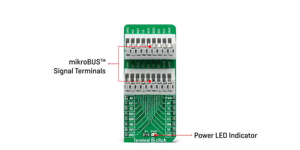
The Terminal 2 Click Board™ is an adapter used as a mikroBUS™ socket expansion board. This Click board™ provides an easy and elegant solution for adding the external connection capability to the Click board™ and can be connected to the mikroBUS™ socket like any other Click board™. On the central area of the Terminal 2 Click Board™, two 9-position 2.54mm pitch terminal blocks are placed. Each of the terminal pins corresponds to a pin on the mikroBUS™ socket. Thanks to these terminals, the connection with the Click board™ remains firm and stable, retaining a perfect connection quality at all times.
Lines of the mikroBUS™ socket to which Terminal 2 Click is attached are shared through the onboard connectors, which mirrors the connected mikroBUS™ socket pins. Therefore, care should be taken when working with the Terminal 2 Click and connecting an external device to it, because the same pins on the mikroBUS™ are shared, either for the communication (SPI, UART, I2C) or for some other purpose (RST, INT, or other pins used as GPIO).
The Terminal 2 Click Board™ can operate with both 3.3V and 5V logic voltage levels. This way, it is allowed for both 3.3V and 5V capable MCUs to use the communication lines properly. A green LED visually detects the presence of an active power supply, labelled as PWR. However, the Click board™ comes equipped with a library containing easy-to-use functions and an example code that can be used, as a reference, for further development.
| Type | Adapter |
| Applications | The Terminal 2 Click Board™ be used as a mikroBUS™ socket expansion board |
| On-board modules | None |
| Key Features | Easy and elegant solution for adding the external connection capability to the Click board™ |
| Interface | Analog,GPIO,I2C,SPI,UART |
| Compatibility | mikroBUS |
| Click board size | L (57.15 x 25.4 mm) |
| Input Voltage | 3.3V or 5V |
This table shows how the pinout on the Terminal 2 Click Board™ corresponds to the pinout on the mikroBUS™ socket (the latter shown in the two middle columns).
| Notes | Pin | Pin | Notes | ||||
|---|---|---|---|---|---|---|---|
| Analog Input | AN | 1 | AN | PWM | 16 | PWM | PWM Output |
| Reset | RST | 2 | RST | INT | 15 | INT | Interrupt |
| SPI Chip Select | CS | 3 | CS | RX | 14 | TX | UART TX |
| SPI Clock | SCK | 4 | SCK | TX | 13 | RX | UART RX |
| SPI Data OUT | SDO | 5 | MISO | SCL | 12 | SCL | I2C Clock |
| SPI Data IN | SDI | 6 | MOSI | SDA | 11 | SDA | I2C Data |
| Power Supply | 3.3V | 7 | 3.3V | 5V | 10 | 5V | Power Supply |
| Ground | GND | 8 | GND | GND | 9 | GND | Ground |
| Label | Name | Default | Description |
|---|---|---|---|
| LD1 | PWR | - | Power LED Indicator |
We provide a library for the Terminal 2 Click Board™ as well as a demo application (example), developed using MikroElektronika compilers. The demo can run on all the main MikroElektronika development boards.
The package can be downloaded/installed directly from NECTO Studio The package Manager (recommended), downloaded from our LibStock™ or found on Mikroe Github account.
Library Description
This library contains API for the Terminal 2 Click Board™ driver.
Key functions
terminal2_set_all_pins_high This function sets all terminal pins to high logic level.
terminal2_set_all_pins_low This function sets all terminal pins to low logic level.
terminal2_toggle_pin This function toggles the specified pin logic level.
Example Description
This example demonstates the use of the Terminal 2 Click Board™ by toggling all its pins.
void application_task ( void )
 {
     /**< Array of pins object addresses. */
     static digital_out_t *pin_addr[ 12 ] =
     {
         &terminal2.mosi,    // 0 MOSI
         &terminal2.miso,    // 1 MISO
         &terminal2.sck,     // 2 SCK
         &terminal2.cs,      // 3 CS
         &terminal2.rst,     // 4 RST
         &terminal2.an,      // 5 AN
         &terminal2.pwm,     // 6 PWM
         &terminal2.int_pin, // 7 INT
         &terminal2.tx_pin,  // 8 TX
         &terminal2.rx_pin,  // 9 RX
         &terminal2.scl,     // 10 SCL
         &terminal2.sda      // 11 SDA
     };
     static uint8_t pin_num = 0;
     log_printf( &logger, " Toggling pin: %urn", ( uint16_t ) pin_num );
     terminal2_toggle_pin ( pin_addr[ pin_num ] );
     Delay_ms ( 1000 );
     terminal2_toggle_pin ( pin_addr[ pin_num ] );

     pin_num++;
     if ( 12 == pin_num )
     {
         pin_num = 0;
     }
 }
The full application code, and ready to use projects can be installed directly from NECTO Studio The package Manager (recommended), downloaded from our LibStock™ or found on Mikroe Github account.
Other Mikroe Libraries used in the example:
Additional Notes and Information
Depending on the development board you are using, you may need a USB UART Click, USB UART 2 Click or RS232 Click to connect to your PC, for development systems with no UART to USB interface available on the board. UART terminal is available in all MikroElektronika compilers.
The Terminal 2 Click Board™ is supported with mikroSDK - MikroElektronika Software Development Kit. To ensure proper operation of mikroSDK compliant Click board™ demo applications, mikroSDK should be downloaded from the LibStock and installed for the compiler you are using.
- examples:We provide a library for the Terminal 2 Click Board™ as well as a demo application (example), developed using MikroElektronika compilers. The demo can run on all the main MikroElektronika development boards.
The package can be downloaded/installed directly from NECTO Studio The package Manager (recommended), downloaded from our LibStock™ or found on Mikroe Github account.
This library contains API for the Terminal 2 Click Board™ driver.
Key functions
terminal2_set_all_pins_high This function sets all terminal pins to high logic level.
terminal2_set_all_pins_low This function sets all terminal pins to low logic level.
terminal2_toggle_pin This function toggles the specified pin logic level.
This example demonstates the use of the Terminal 2 Click Board™ by toggling all its pins.
void application_task ( void )
 {
     /**< Array of pins object addresses. */
     static digital_out_t *pin_addr[ 12 ] =
     {
         &terminal2.mosi,    // 0 MOSI
         &terminal2.miso,    // 1 MISO
         &terminal2.sck,     // 2 SCK
         &terminal2.cs,      // 3 CS
         &terminal2.rst,     // 4 RST
         &terminal2.an,      // 5 AN
         &terminal2.pwm,     // 6 PWM
         &terminal2.int_pin, // 7 INT
         &terminal2.tx_pin,  // 8 TX
         &terminal2.rx_pin,  // 9 RX
         &terminal2.scl,     // 10 SCL
         &terminal2.sda      // 11 SDA
     };
     static uint8_t pin_num = 0;
     log_printf( &logger, " Toggling pin: %urn", ( uint16_t ) pin_num );
     terminal2_toggle_pin ( pin_addr[ pin_num ] );
     Delay_ms ( 1000 );
     terminal2_toggle_pin ( pin_addr[ pin_num ] );

     pin_num++;
     if ( 12 == pin_num )
     {
         pin_num = 0;
     }
 }
The full application code, and ready to use projects can be installed directly from NECTO Studio The package Manager (recommended), downloaded from our LibStock™ or found on Mikroe Github account.
Other Mikroe Libraries used in the example:
Depending on the development board you are using, you may need a USB UART Click, USB UART 2 Click or RS232 Click to connect to your PC, for development systems with no UART to USB interface available on the board. UART terminal is available in all MikroElektronika compilers.
The Terminal 2 Click Board™ is supported with mikroSDK - MikroElektronika Software Development Kit. To ensure proper operation of mikroSDK compliant Click board™ demo applications, mikroSDK should be downloaded from the LibStock and installed for the compiler you are using.
- manufacturer: Mikroelektronika d.o.o. - warranty: 12 months - backorder_label: If no stock shown above, check availability - attachments: [{"download_file":[{"download_file":"Terminal 2 Click Board™ Schematic"}],"download_filetype":[{"download_filetype":"pdf"}]}] - condition: new - custom_product: false - mpn: MIKROE-4951 - google_product_category: Electronics - custom_label_0: Click Board - mpn: MIKROE-4951 - myordercount: {"ordercount":1,"recentcount":1} - warranty: 12 months - brand: MikroE - manufacturer: Mikroelektronika d.o.o. - target_keyword: Terminal 2 Click Board - brands: gid://shopify/Metaobject/56256004319 - breadcrumbs: ["gid://shopify/Collection/447955239135","gid://shopify/Collection/241680580797"] - customhs_code: 847330 - detailed_description: {"type":"root","children":[{"type":"heading","level":3,"children":[{"type":"text","value":"How Does The Terminal 2 Click Board™ Work?"}]},{"type":"paragraph","children":[{"type":"text","value":"The "},{"type":"text","value":"Terminal 2 Click Board™","bold":true,"italic":true},{"type":"text","value":" is an adapter used as a mikroBUS™ socket expansion board. This Click board™ provides an easy and elegant solution for adding the external connection capability to the Click board™ and can be connected to the mikroBUS™ socket like any other Click board™. On the central area of the "},{"type":"text","value":"Terminal 2 Click Board™","bold":true},{"type":"text","value":", two 9-position 2.54mm pitch terminal blocks are placed. Each of the terminal pins corresponds to a pin on the mikroBUS™ socket. Thanks to these terminals, the connection with the Click board™ remains firm and stable, retaining a perfect connection quality at all times."}]},{"type":"paragraph","children":[{"type":"text","value":""}]},{"type":"paragraph","children":[{"type":"text","value":"Lines of the mikroBUS™ socket to which Terminal 2 Click is attached are shared through the onboard connectors, which mirrors the connected mikroBUS™ socket pins. Therefore, care should be taken when working with the Terminal 2 Click and connecting an external device to it, because the same pins on the mikroBUS™ are shared, either for the communication (SPI, UART, I2C) or for some other purpose (RST, INT, or other pins used as GPIO)."}]},{"type":"paragraph","children":[{"type":"text","value":"The "},{"type":"text","value":"Terminal 2 Click Board™","bold":true},{"type":"text","value":" can operate with both 3.3V and 5V logic voltage levels. This way, it is allowed for both 3.3V and 5V capable MCUs to use the communication lines properly. A green LED visually detects the presence of an active power supply, labelled as PWR. However, the Click board™ comes equipped with a library containing easy-to-use functions and an example code that can be used, as a reference, for further development."}]},{"type":"heading","level":3,"children":[{"type":"text","value":"SPECIFICATIONS"}]},{"type":"paragraph","children":[{"type":"text","value":"Type\nAdapter\nApplications\nThe Terminal 2 Click Board™ be used as a mikroBUS™ socket expansion board\nOn-board modules\nNone\nKey Features\nEasy and elegant solution for adding the external connection capability to the Click board™\nInterface\nAnalog,GPIO,I2C,SPI,UART\nCompatibility\nmikroBUS\nClick board size\nL (57.15 x 25.4 mm)\nInput Voltage\n3.3V or 5V"}]},{"type":"heading","level":3,"children":[{"type":"text","value":"PINOUT DIAGRAM"}]},{"type":"paragraph","children":[{"type":"text","value":"This table shows how the pinout on the "},{"type":"text","value":"Terminal 2 Click Board™","bold":true},{"type":"text","value":" corresponds to the pinout on the mikroBUS™ socket (the latter shown in the two middle columns)."}]},{"type":"paragraph","children":[{"type":"text","value":"Notes\nPin\nPin\nNotes\nAnalog Input\nAN\n1\nAN\nPWM\n16\nPWM\nPWM Output\nReset\nRST\n2\nRST\nINT\n15\nINT\nInterrupt\nSPI Chip Select\nCS\n3\nCS\nRX\n14\nTX\nUART TX\nSPI Clock\nSCK\n4\nSCK\nTX\n13\nRX\nUART RX\nSPI Data OUT\nSDO\n5\nMISO\nSCL\n12\nSCL\nI2C Clock\nSPI Data IN\nSDI\n6\nMOSI\nSDA\n11\nSDA\nI2C Data\nPower Supply\n3.3V\n7\n3.3V\n5V\n10\n5V\nPower Supply\nGround\nGND\n8\nGND\nGND\n9\nGND\nGround"}]},{"type":"heading","level":3,"children":[{"type":"text","value":"ONBOARD SETTINGS AND INDICATORS"}]},{"type":"paragraph","children":[{"type":"text","value":"Label\nName\nDefault\nDescription\nLD1\nPWR\n-\nPower LED Indicator"}]},{"type":"heading","level":3,"children":[{"type":"text","value":"Software Support"}]},{"type":"paragraph","children":[{"type":"text","value":"We provide a library for the "},{"type":"text","value":"Terminal 2 Click Board™","bold":true},{"type":"text","value":" as well as a demo application (example), developed using MikroElektronika compilers. The demo can run on all the main MikroElektronika development boards."}]},{"type":"paragraph","children":[{"type":"text","value":"The package can be downloaded/installed directly from NECTO Studio The package Manager (recommended), downloaded from our LibStock™ or found on Mikroe Github account."}]},{"type":"paragraph","children":[{"type":"text","value":"Library Description","bold":true}]},{"type":"paragraph","children":[{"type":"text","value":"This library contains API for the "},{"type":"text","value":"Terminal 2 Click Board™","bold":true},{"type":"text","value":" driver."}]},{"type":"paragraph","children":[{"type":"text","value":"Key functions"}]},{"type":"list","listType":"unordered","children":[{"type":"list-item","children":[{"type":"text","value":" "},{"type":"text","value":"terminal2_set_all_pins_high"},{"type":"text","value":" This function sets all terminal pins to high logic level."},{"type":"text","value":" "}]},{"type":"list-item","children":[{"type":"text","value":" "},{"type":"text","value":"terminal2_set_all_pins_low"},{"type":"text","value":" This function sets all terminal pins to low logic level."},{"type":"text","value":" "}]},{"type":"list-item","children":[{"type":"text","value":" "},{"type":"text","value":"terminal2_toggle_pin"},{"type":"text","value":" This function toggles the specified pin logic level."},{"type":"text","value":" "}]}]},{"type":"paragraph","children":[{"type":"text","value":"Example Description","bold":true}]},{"type":"paragraph","children":[{"type":"text","value":"This example demonstates the use of the "},{"type":"text","value":"Terminal 2 Click Board™","bold":true},{"type":"text","value":" by toggling all its pins."}]},{"type":"paragraph","children":[{"type":"text","value":"void application_task ( void ) \n { \n /**< Array of pins object addresses. */ \n static digital_out_t *pin_addr[ 12 ] = \n { \n &terminal2.mosi, // 0 MOSI \n &terminal2.miso, // 1 MISO \n &terminal2.sck, // 2 SCK \n &terminal2.cs, // 3 CS \n &terminal2.rst, // 4 RST \n &terminal2.an, // 5 AN \n &terminal2.pwm, // 6 PWM \n &terminal2.int_pin, // 7 INT \n &terminal2.tx_pin, // 8 TX \n &terminal2.rx_pin, // 9 RX \n &terminal2.scl, // 10 SCL \n &terminal2.sda // 11 SDA \n }; \n static uint8_t pin_num = 0; \n log_printf( &logger, \" Toggling pin: %urn\", ( uint16_t ) pin_num ); \n terminal2_toggle_pin ( pin_addr[ pin_num ] ); \n Delay_ms ( 1000 ); \n terminal2_toggle_pin ( pin_addr[ pin_num ] ); \n\n pin_num++; \n if ( 12 == pin_num ) \n { \n pin_num = 0; \n } \n }"}]},{"type":"paragraph","children":[{"type":"text","value":"The full application code, and ready to use projects can be installed directly from NECTO Studio The package Manager (recommended), downloaded from our LibStock™ or found on Mikroe Github account."}]},{"type":"paragraph","children":[{"type":"text","value":"Other Mikroe Libraries used in the example:"}]},{"type":"list","listType":"unordered","children":[{"type":"list-item","children":[{"type":"text","value":"MikroSDK.Board"}]},{"type":"list-item","children":[{"type":"text","value":"MikroSDK.Log"}]},{"type":"list-item","children":[{"type":"text","value":"Click.Terminal2"}]}]},{"type":"paragraph","children":[{"type":"text","value":"Additional Notes and Information","bold":true}]},{"type":"paragraph","children":[{"type":"text","value":"Depending on the development board you are using, you may need a USB UART Click, USB UART 2 Click or RS232 Click to connect to your PC, for development systems with no UART to USB interface available on the board. UART terminal is available in all MikroElektronika compilers."}]},{"type":"heading","level":3,"children":[{"type":"text","value":"MIKROSDK"}]},{"type":"paragraph","children":[{"type":"text","value":"The "},{"type":"text","value":"Terminal 2 Click Board™","bold":true},{"type":"text","value":" is supported with mikroSDK - MikroElektronika Software Development Kit. To ensure proper operation of mikroSDK compliant Click board™ demo applications, mikroSDK should be downloaded from the LibStock and installed for the compiler you are using."}]}]} - summary:The Terminal 2 Click Board™ is an adapter used as a mikroBUS™ socket expansion board. It provides an easy and elegant solution for adding the external connection capability to the Click board™, plugged on a mikroBUS™ socket. Featuring two 9-position 2.54mm pitch terminal blocks makes it an easy way to expand the development system's connectivity with the mikroBUS™ socket while keeping the bus free to use with any Click board™.
The Terminal 2 Click Board™ is supported by a mikroSDK compliant library, which includes functions that simplify software development. This Click board™ comes as a fully tested product, ready to be used on a system equipped with the mikroBUS™ socket.