The DC Motor 20 Click Board™ is based on the TC78H651AFNG, a dual H-bridge driver for one or two DC brushed motors from Toshiba Semiconductor. The integrated MOSFETs, which configures with an H-Bridge circuit inside the TC78H651AFNG, use DMOS elements with low-on resistance (0.22Ω typical with 5V power supply). It has a wide operating voltage range with an output current capacity of 2A maximum and control functions including motor-related functions and built-in detection circuits for overcurrent, overheat, and low/high voltage.
As mentioned in the product description, the DC Motor 20 Click Board™ communicates with MCU using several GPIO pins. Also, this Click board™ has a Standby function used to switch to Standby mode by setting all motor control pins to a low logic state. When the Standby mode is active, the TC78H651AFNG stops supplying the power to the logic circuit. The Standby current is significantly reduced because all circuits in the IC are configured with CMOS/DMOS elements, and the current consumption in this mode is 0μA typical.
To turn ON the internal MOSFETs of the TC78H651AFNG, they need to be switched by the logic level, which is input to the control input pins: IN1, IN2, IN3, and IN4 pins routed to the RST, AN, PWM, and INT pins of the mikroBUS™ socket. Thereby, the Forward/Reverse/Stop rotation direction mode can be selected according to the state of its input control signals. More information on the Motor Rotation Mode Selection can be found in the attached datasheet.
The DC Motor 20 Click Board™ can operate with both 3.3V and 5V logic voltage levels selected via the VCC SEL jumper. This way, it is allowed for both 3.3V and 5V capable MCUs to use communication lines properly. However, the Click board™ comes equipped with a library containing easy-to-use functions and an example code that can be used, as a reference, for further development.
| Type | Brushed |
| Applications | Can be used for driving DC brushed motors and stepping motors for low voltage equipment |
| On-board modules | TC78H651AFNG - dual H-bridge driver for one or two DC brushed motors from Toshiba Semiconductor |
| Key Features | Low power consumption, dual bridge driver, high drive capability, low voltage drive, low-on resistance, selectable motor operation, built-in Standby and protection features, and more |
| Interface | GPIO |
| Compatibility | mikroBUS |
| Click board size | M (42.9 x 25.4 mm) |
| Input Voltage | 3.3V or 5V,External |
This table shows how the pinout on the DC Motor 20 Click Board™ corresponds to the pinout on the mikroBUS™ socket (the latter shown in the two middle columns).
| Notes | Pin | Pin | Notes | ||||
|---|---|---|---|---|---|---|---|
| Motor Control Input 1 | IN1 | 1 | AN | PWM | 16 | IN3 | Motor Control Input 3 |
| Motor Control Input 2 | IN2 | 2 | RST | INT | 15 | IN4 | Motor Control Input 4 |
| NC | 3 | CS | RX | 14 | NC | ||
| NC | 4 | SCK | TX | 13 | NC | ||
| NC | 5 | MISO | SCL | 12 | NC | ||
| NC | 6 | MOSI | SDA | 11 | NC | ||
| Power Supply | 3.3V | 7 | 3.3V | 5V | 10 | 5V | Power Supply |
| Ground | GND | 8 | GND | GND | 9 | GND | Ground |
| Label | Name | Default | Description |
|---|---|---|---|
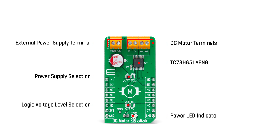
| LD1 | PWR | - | Power LED Indicator |
| JP1 | VCC SEL | Left | Logic Level Voltage Selection 3V3/5V: Left position 3V3, Right position 5V |
| JP2 | VM SEL | Left | TC78H651AFNG Power Supply Selection VEXT/VCC: Left position VEXT, Right position VCC |
| Description | Min | Typ | Max | Unit |
|---|---|---|---|---|
| Supply Voltage VCC | 3.3 | - | 5 | V |
| External Power Supply VM | 1.8 | - | 7.5 | V |
| Maximum Output Current | - | - | 2 | A |
| Operating Temperature Range | -40 | +25 | +105 | °C |
We provide a library for the DC Motor 20 Click Board™ as well as a demo application (example), developed using MikroElektronika compilers. The demo can run on all the main MikroElektronika development boards.
Package can be downloaded/installed directly from NECTO Studio Package Manager(recommended way), downloaded from our LibStock™ or found on Mikroe Github account.
This library contains API for the DC Motor 20 Click Board™ driver.
Key functions
dcmotor20_drive_motor This function drives the motor for a certian time specified by time_ms at the desired speed.
dcmotor20_set_channel_mode This function sets the active channel and mode which will be used by the dcmotor20_drive_motor function.
dcmotor20_set_standby_mode This function sets the chip to the standby mode which affects both channels.
This example demonstrates the use of the DC Motor 20 Click Board™ by driving the motors in both direction in the span of 14 seconds.
 void application_task ( void )
 {
     log_printf ( &logger, " Driving motors forward...rn" );
     dcmotor20_set_channel_mode ( &dcmotor20, DCMOTOR20_CHANNEL_1 | DCMOTOR20_CHANNEL_2, DCMOTOR20_MODE_FORWARD );
     dcmotor20_drive_motor ( &dcmotor20, DCMOTOR20_SPEED_DEFAULT, 5000 );
     log_printf ( &logger, " Pull brake!rn" );
     dcmotor20_set_standby_mode ( &dcmotor20 );
     Delay_ms( 2000 );
     log_printf ( &logger, " Driving motors in reverse...rn" );
     dcmotor20_set_channel_mode ( &dcmotor20, DCMOTOR20_CHANNEL_1 | DCMOTOR20_CHANNEL_2, DCMOTOR20_MODE_REVERSE );
     dcmotor20_drive_motor ( &dcmotor20, DCMOTOR20_SPEED_DEFAULT, 5000 );
     log_printf ( &logger, " Pull brake!rnn" );
     dcmotor20_set_standby_mode ( &dcmotor20 );
     Delay_ms( 2000 );
 }
The full application code, and ready to use projects can be installed directly from NECTO Studio Package Manager(recommended way), downloaded from our LibStock™ or found on Mikroe Github account.
Other Mikroe Libraries used in the example:
Depending on the development board you are using, you may need a USB UART click, USB UART 2 Click or RS232 Click to connect to your PC, for development systems with no UART to USB interface available on the board. UART terminal is available in all MikroElektronika compilers.
The DC Motor 20 Click Board™ is supported with mikroSDK - MikroElektronika Software Development Kit. To ensure proper operation of mikroSDK compliant Click board™ demo applications, mikroSDK should be downloaded from the LibStock and installed for the compiler you are using.
- manufacturer: Mikroelektronika d.o.o. - warranty: 12 months - backorder_label: If no stock shown above, check availability - attachments: [{"download_file":[{"download_file":"DC Motor 20 Click Board™ Schematic"}],"download_filetype":[{"download_filetype":"pdf"}]},{"download_file":[{"download_file":"Toshiba TC78H651AFNG Brushed DC Motor Driver Datasheet"}],"download_filetype":[{"download_filetype":"pdf"}]}] - condition: new - custom_product: false - mpn: MIKROE-4884 - google_product_category: Electronics - custom_label_0: Click Board - mpn: MIKROE-4884 - device_vendor: Toshiba Semiconductor and Storage - device_type: TC78H651AFNG,EL - warranty: 12 months - brand: MikroE - manufacturer: Mikroelektronika d.o.o. - target_keyword: DC Motor 20 Click Board - brands: gid://shopify/Metaobject/56256004319 - breadcrumbs: ["gid://shopify/Collection/447955239135","gid://shopify/Collection/241680580797","gid://shopify/Collection/241545248957","gid://shopify/Collection/279405134013"] - customhs_code: 847330 - detailed_description: {"type":"root","children":[{"type":"heading","level":3,"children":[{"type":"text","value":"How Does The DC Motor 20 Click Board™ Work?"}]},{"type":"paragraph","children":[{"type":"text","value":"The "},{"type":"text","value":"DC Motor 20 Click Board™","bold":true,"italic":true},{"type":"text","value":" is based on the TC78H651AFNG, a dual H-bridge driver for one or two DC brushed motors from Toshiba Semiconductor. The integrated MOSFETs, which configures with an H-Bridge circuit inside the TC78H651AFNG, use DMOS elements with low-on resistance (0.22Ω typical with 5V power supply). It has a wide operating voltage range with an output current capacity of 2A maximum and control functions including motor-related functions and built-in detection circuits for overcurrent, overheat, and low/high voltage."}]},{"type":"paragraph","children":[{"type":"text","value":""}]},{"type":"paragraph","children":[{"type":"text","value":"As mentioned in the product description, the "},{"type":"text","value":"DC Motor 20 Click Board™","bold":true},{"type":"text","value":" communicates with MCU using several GPIO pins. Also, this Click board™ has a Standby function used to switch to Standby mode by setting all motor control pins to a low logic state. When the Standby mode is active, the TC78H651AFNG stops supplying the power to the logic circuit. The Standby current is significantly reduced because all circuits in the IC are configured with CMOS/DMOS elements, and the current consumption in this mode is 0μA typical."}]},{"type":"paragraph","children":[{"type":"text","value":"To turn ON the internal MOSFETs of the TC78H651AFNG, they need to be switched by the logic level, which is input to the control input pins: IN1, IN2, IN3, and IN4 pins routed to the RST, AN, PWM, and INT pins of the mikroBUS™ socket. Thereby, the Forward/Reverse/Stop rotation direction mode can be selected according to the state of its input control signals. More information on the Motor Rotation Mode Selection can be found in the attached datasheet."}]},{"type":"paragraph","children":[{"type":"text","value":"The "},{"type":"text","value":"DC Motor 20 Click Board™","bold":true},{"type":"text","value":" can operate with both 3.3V and 5V logic voltage levels selected via the VCC SEL jumper. This way, it is allowed for both 3.3V and 5V capable MCUs to use communication lines properly. However, the Click board™ comes equipped with a library containing easy-to-use functions and an example code that can be used, as a reference, for further development."}]},{"type":"heading","level":3,"children":[{"type":"text","value":"SPECIFICATIONS"}]},{"type":"paragraph","children":[{"type":"text","value":"Type\nBrushed\nApplications\nCan be used for driving DC brushed motors and stepping motors for low voltage equipment\nOn-board modules\nTC78H651AFNG - dual H-bridge driver for one or two DC brushed motors from Toshiba Semiconductor\nKey Features\nLow power consumption, dual bridge driver, high drive capability, low voltage drive, low-on resistance, selectable motor operation, built-in Standby and protection features, and more\nInterface\nGPIO\nCompatibility\nmikroBUS\nClick board size\nM (42.9 x 25.4 mm)\nInput Voltage\n3.3V or 5V,External"}]},{"type":"heading","level":3,"children":[{"type":"text","value":"PINOUT DIAGRAM"}]},{"type":"paragraph","children":[{"type":"text","value":"This table shows how the pinout on the "},{"type":"text","value":"DC Motor 20 Click Board™","bold":true},{"type":"text","value":" corresponds to the pinout on the mikroBUS™ socket (the latter shown in the two middle columns)."}]},{"type":"paragraph","children":[{"type":"text","value":"Notes\nPin\nPin\nNotes\nMotor Control Input 1\nIN1\n1\nAN\nPWM\n16\nIN3\nMotor Control Input 3\nMotor Control Input 2\nIN2\n2\nRST\nINT\n15\nIN4\nMotor Control Input 4\nNC\n3\nCS\nRX\n14\nNC\nNC\n4\nSCK\nTX\n13\nNC\nNC\n5\nMISO\nSCL\n12\nNC\nNC\n6\nMOSI\nSDA\n11\nNC\nPower Supply\n3.3V\n7\n3.3V\n5V\n10\n5V\nPower Supply\nGround\nGND\n8\nGND\nGND\n9\nGND\nGround"}]},{"type":"heading","level":3,"children":[{"type":"text","value":"ONBOARD SETTINGS AND INDICATORS"}]},{"type":"paragraph","children":[{"type":"text","value":"Label\nName\nDefault\n Description\nLD1\nPWR\n-\nPower LED Indicator\nJP1\nVCC SEL\nLeft\nLogic Level Voltage Selection 3V3/5V: Left position 3V3, Right position 5V\nJP2\nVM SEL\nLeft\nTC78H651AFNG Power Supply Selection VEXT/VCC: Left position VEXT, Right position VCC"}]},{"type":"heading","level":3,"children":[{"type":"text","value":"DC MOTOR 20 CLICK ELECTRICAL SPECIFICATIONS"}]},{"type":"paragraph","children":[{"type":"text","value":"Description\nMin\nTyp\nMax\nUnit\nSupply Voltage VCC\n3.3\n-\n5\nV\nExternal Power Supply VM\n1.8\n-\n7.5\nV\nMaximum Output Current\n-\n-\n2\nA\nOperating Temperature Range\n-40\n+25\n+105\n°C"}]},{"type":"heading","level":3,"children":[{"type":"text","value":" "}]}]} - summary:The DC Motor 20 Click Board™ is a compact add-on board that contains a brushed DC motor driver. This board features the TC78H651AFNG, a dual H-bridge driver for one or two DC brushed motors, which incorporates DMOS with low ON resistance in output transistors from Toshiba Semiconductor. The Forward/Reverse/Stop mode can be selected according to the state of its input control signals routed to the GPIO pins of the mikroBUS™ socket. It has a wide operating voltage range of 1.8V to 7.5V with an output current capacity of 2A maximum. Besides, it also features built-in protection against under-voltage, overcurrent, and overtemperature conditions.
The DC Motor 20 Click Board™ is suitable for driving DC brushed motors and stepping motors for low voltage equipment.