The Buck 16 Click Board™ as its foundation uses the TPS62912, a low-noise, low-ripple synchronous buck converter with a fixed-frequency current-mode from Texas Instruments. This converter has a filtered internal reference that achieves a low-noise output similar to low-noise LDOs. Besides, it has an output-voltage error of less than 1%, which helps ensure tight output-voltage accuracy, and lower output voltage ripple achieved by using a switching frequency of either 2.2MHz or 1MHz. That's why this Click board™ is suitable for noise-sensitive applications that generally use an LDO for post-regulation.
The Buck 16 Click Board™ communicates with MCU using one GPIO pin in addition to a 3-wire SPI serial interface. The device-enable feature, routed to the RST pin of the mikroBUS™ socket, optimizes power consumption and is used for power ON/OFF purposes (driver operation permission). Once the Click board™ is enabled, the operation mode is then set by the configuration of the CONF SEL (Smart Configuration) jumper by positioning the SMD jumper to an appropriate position marked as VIN or GND.
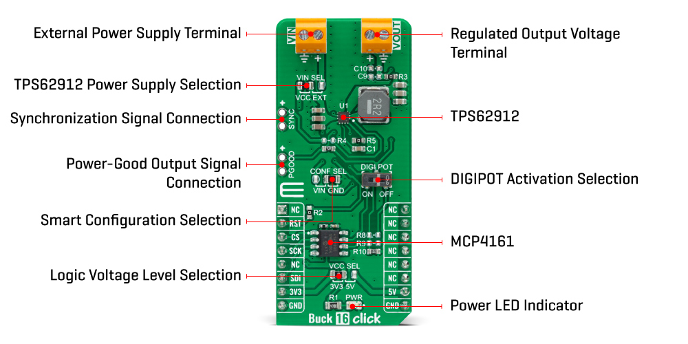
Besides, this pin is also used for device synchronization. Once an external clock signal, which must be within the clock synchronization frequency range set by the Smart Configuration jumper, is applied to this pin through an onboard header marked as SYNC, the device is enabled and reads the configuration of the Smart Configuration pin. When this signal changes from a clock to a static high, the device switches from an external clock to an internal clock.
With all that, this device also has a power-good output available on the onboard header labeled as PGOOD. The PGOOD pin goes into a high impedance state once the feedback pin voltage, obtained by the MCP4161 digital potentiometer and controlled by the DIGI POT switch, is above 95% of the nominal voltage and is driven low once the voltage falls below typically 90% of the nominal voltage. The power-good signal can be used to sequence multiple rails by connecting to the enable pin of other converters.
The Buck 16 Click Board™ can operate with both 3.3V and 5V logic voltage levels selected via the VCC SEL jumper. It allows for both 3.3V and 5V capable MCUs to use the communication lines properly. Additionally, there is a possibility for the TPS62912 power supply selection via jumper labeled as VIN SEL to supply the TPS62912 from an external power supply terminal in the range from 3 to 17V or with VCC voltage levels from mikroBUS™ power rails. However, the Click board™ comes equipped with a library containing easy-to-use functions and an example code that can be used, as a reference, for further development.
| Type | Buck |
| Applications | Can be used for noise-sensitive applications that generally use an LDO for post-regulation, such as high-speed ADCs, clock and jitter cleaner, serializer, de-serializer, and radar applications |
| On-board modules | TPS62912 - low-noise, low-ripple synchronous buck converter with a fixed-frequency current-mode from Texas Instrument |
| Key Features | Low output noise and voltage ripple, 2.2MHz or 1MHz fixed frequency peak current mode control, synchronizable with external clock, output voltage accuracy of ±1%, power-good output, and more |
| Interface | GPIO,SPI |
| Compatibility | mikroBUS |
| Click board size | L (57.15 x 25.4 mm) |
| Input Voltage | 3.3V or 5V,External |
This table shows how the pinout on the Buck 16 Click Board™ corresponds to the pinout on the mikroBUS™ socket (the latter shown in the two middle columns).
| Notes | Pin | Pin | Notes | ||||
|---|---|---|---|---|---|---|---|
| NC | 1 | AN | PWM | 16 | NC | ||
| Enable | RST | 2 | RST | INT | 15 | NC | |
| SPI Chip Select | CS | 3 | CS | RX | 14 | NC | |
| SPI Clock | SCK | 4 | SCK | TX | 13 | NC | |
| NC | 5 | MISO | SCL | 12 | NC | ||
| SPI Data IN | SDI | 6 | MOSI | SDA | 11 | NC | |
| Power Supply | 3.3V | 7 | 3.3V | 5V | 10 | 5V | Power Supply |
| Ground | GND | 8 | GND | GND | 9 | GND | Ground |
| Label | Name | Default | Description |
|---|---|---|---|
| LD1 | PWR | - | Power LED Indicator |
| JP1 | VCC SEL | Left | Logic Level Voltage Selection 3V3/5V: Left position 3V3, Right position 5V |
| JP2 | VIN SEL | Left | TPS62912 Power Supply Selection VCC/EXT: Left position VCC, Right position EXT |
| JP3 | CONF SEL | Right | Smart Configuration Selection VIN/GND: Left position VIN, Right position GND |
| J1 | SYNC | Unpopulated | Synchronization Signal Header |
| J2 | PGOOD | Unpopulated | Power-Good Output Signal Header |
| SW1 | DIGI POT | - | DIGIPOT Activation Switch |
| Description | Min | Typ | Max | Unit |
|---|---|---|---|---|
| Supply Voltage VCC | 3.3 | - | 5 | V |
| Supply Voltage VIN | 3 | - | 17 | V |
| Maximum Output Current | - | - | 2 | A |
| Operating Temperature Range | -40 | +25 | +125 | °C |
We provide a library for the Buck 16 Click Board™ as well as a demo application (example), developed using MikroElektronika compilers. The demo can run on all the main MikroElektronika development boards.
The package can be downloaded/installed directly from NECTO Studio Package Manager(recommended way), downloaded from our LibStock™ or found on Mikroe Github account.
This library contains API for the Buck 16 Click Board™.
buck16_enable_output - Enable/Disable voltage output.buck16_set_potentiometer - Set potentiometer resistivity.buck16_set_output - Set output voltage.This example showcases ability of the device to control voltage output of device. Output voltage can range from 800 to 5500 depending of VIN. By default it will go from 800 to 3300 VIN==VCC.
void application_task ( void )
{
    log_printf( &logger, " > Setting output to 0.9Vrn" );
    buck16_set_output( &buck16, 900 );
    Delay_ms( 5000 );
    log_printf( &logger, " > Setting output to 2.5Vrn" );
    buck16_set_output( &buck16, 2500 );
    Delay_ms( 5000 );
    log_printf( &logger, " > Disable outputrn" );
    buck16_enable_output( &buck16, 0 );
    Delay_ms( 3000 );
    log_printf( &logger, " > Enable outputrn" );
    buck16_enable_output( &buck16, 1 );
    Delay_ms( 3000 );
    log_printf( &logger, " > Setting output to 1.5Vrn" );
    buck16_set_output( &buck16, 1500 );
    Delay_ms( 5000 );
}
The full application code, and ready to use projects can be installed directly from NECTO Studio Package Manager(recommended way), downloaded from our LibStock™ or found on Mikroe github account.
Other mikroE Libraries used in the example:
Depending on the development board you are using, you may need USB UART click, USB UART 2 click or RS232 click to connect to your PC, for development systems with no UART to USB interface available on the board. The terminal available in all MikroElektronika compilers, or any other terminal application of your choice, can be used to read the message.
The Buck 16 Click Board™ is supported with mikroSDK - MikroElektronika Software Development Kit. To ensure proper operation of mikroSDK compliant Click board™ demo applications, mikroSDK should be downloaded from the LibStock and installed for the compiler you are using.
- manufacturer: Mikroelektronika d.o.o. - warranty: 12 months - backorder_label: If no stock shown above, check availability - attachments: [{"download_file":[{"download_file":"Buck 16 Click Board™ Schematic"}],"download_filetype":[{"download_filetype":"pdf"}]},{"download_file":[{"download_file":"Texas Instruments TPS62912 Buck Converter Datasheet"}],"download_filetype":[{"download_filetype":"pdf"}]},{"download_file":[{"download_file":"Microchip MCP4161 Digital Potentiometer Datasheet"}],"download_filetype":[{"download_filetype":"pdf"}]}] - condition: new - custom_product: false - mpn: MIKROE-4846 - google_product_category: Electronics - custom_label_0: Click Board - mpn: MIKROE-4846 - device_vendor: Microchip Technology, Texas Instruments - device_type: MCP4161-103E/SN, TPS62912RPUR - warranty: 12 months - brand: MikroE - manufacturer: Mikroelektronika d.o.o. - target_keyword: Buck 16 Click Board - brands: gid://shopify/Metaobject/56256004319 - breadcrumbs: ["gid://shopify/Collection/447955239135","gid://shopify/Collection/241680580797","gid://shopify/Collection/241545478333"] - customhs_code: 847330 - detailed_description: {"type":"root","children":[{"type":"heading","level":3,"children":[{"type":"text","value":"How Does The Buck 16 Click Board™ Work?"}]},{"type":"paragraph","children":[{"type":"text","value":"The"},{"type":"text","value":" Buck 16 Click Board™","bold":true,"italic":true},{"type":"text","value":" ","italic":true},{"type":"text","value":"as its foundation uses the TPS62912, a low-noise, low-ripple synchronous buck converter with a fixed-frequency current-mode from Texas Instruments. This converter has a filtered internal reference that achieves a low-noise output similar to low-noise LDOs. Besides, it has an output-voltage error of less than 1%, which helps ensure tight output-voltage accuracy, and lower output voltage ripple achieved by using a switching frequency of either 2.2MHz or 1MHz. That's why this Click board™ is suitable for noise-sensitive applications that generally use an LDO for post-regulation."}]},{"type":"paragraph","children":[{"type":"text","value":""}]},{"type":"paragraph","children":[{"type":"text","value":"The "},{"type":"text","value":"Buck 16 Click Board™","bold":true},{"type":"text","value":" communicates with MCU using one GPIO pin in addition to a 3-wire SPI serial interface. The device-enable feature, routed to the RST pin of the mikroBUS™ socket, optimizes power consumption and is used for power ON/OFF purposes (driver operation permission). Once the Click board™ is enabled, the operation mode is then set by the configuration of the CONF SEL (Smart Configuration) jumper by positioning the SMD jumper to an appropriate position marked as VIN or GND."}]},{"type":"paragraph","children":[{"type":"text","value":"Besides, this pin is also used for device synchronization. Once an external clock signal, which must be within the clock synchronization frequency range set by the Smart Configuration jumper, is applied to this pin through an onboard header marked as SYNC, the device is enabled and reads the configuration of the Smart Configuration pin. When this signal changes from a clock to a static high, the device switches from an external clock to an internal clock."}]},{"type":"paragraph","children":[{"type":"text","value":"With all that, this device also has a power-good output available on the onboard header labeled as PGOOD. The PGOOD pin goes into a high impedance state once the feedback pin voltage, obtained by the MCP4161 digital potentiometer and controlled by the DIGI POT switch, is above 95% of the nominal voltage and is driven low once the voltage falls below typically 90% of the nominal voltage. The power-good signal can be used to sequence multiple rails by connecting to the enable pin of other converters."}]},{"type":"paragraph","children":[{"type":"text","value":"The "},{"type":"text","value":"Buck 16 Click Board™","bold":true},{"type":"text","value":" can operate with both 3.3V and 5V logic voltage levels selected via the VCC SEL jumper. It allows for both 3.3V and 5V capable MCUs to use the communication lines properly. Additionally, there is a possibility for the TPS62912 power supply selection via jumper labeled as VIN SEL to supply the TPS62912 from an external power supply terminal in the range from 3 to 17V or with VCC voltage levels from mikroBUS™ power rails. However, the Click board™ comes equipped with a library containing easy-to-use functions and an example code that can be used, as a reference, for further development."}]},{"type":"heading","level":3,"children":[{"type":"text","value":"Specifications"}]},{"type":"paragraph","children":[{"type":"text","value":"Type\nBuck\nApplications\nCan be used for noise-sensitive applications that generally use an LDO for post-regulation, such as high-speed ADCs, clock and jitter cleaner, serializer, de-serializer, and radar applications\nOn-board modules\nTPS62912 - low-noise, low-ripple synchronous buck converter with a fixed-frequency current-mode from Texas Instrument\nKey Features\nLow output noise and voltage ripple, 2.2MHz or 1MHz fixed frequency peak current mode control, synchronizable with external clock, output voltage accuracy of ±1%, power-good output, and more\nInterface\nGPIO,SPI\nCompatibility\nmikroBUS\nClick board size\nL (57.15 x 25.4 mm)\nInput Voltage\n3.3V or 5V,External"}]},{"type":"heading","level":3,"children":[{"type":"text","value":"Pinout diagram"}]},{"type":"paragraph","children":[{"type":"text","value":"This table shows how the pinout on the "},{"type":"text","value":"Buck 16 Click Board™","bold":true},{"type":"text","value":" corresponds to the pinout on the mikroBUS™ socket (the latter shown in the two middle columns)."}]},{"type":"paragraph","children":[{"type":"text","value":"Notes\nPin\nPin\nNotes\nNC\n1\nAN\nPWM\n16\nNC\nEnable\nRST\n2\nRST\nINT\n15\nNC\nSPI Chip Select\nCS\n3\nCS\nRX\n14\nNC\nSPI Clock\nSCK\n4\nSCK\nTX\n13\nNC\nNC\n5\nMISO\nSCL\n12\nNC\nSPI Data IN\nSDI\n6\nMOSI\nSDA\n11\nNC\nPower Supply\n3.3V\n7\n3.3V\n5V\n10\n5V\nPower Supply\nGround\nGND\n8\nGND\nGND\n9\nGND\nGround"}]},{"type":"heading","level":3,"children":[{"type":"text","value":"Onboard Settings and Indicators"}]},{"type":"paragraph","children":[{"type":"text","value":"Label\nName\nDefault\n Description\nLD1\nPWR\n-\nPower LED Indicator\nJP1\nVCC SEL\nLeft\nLogic Level Voltage Selection 3V3/5V: Left position 3V3, Right position 5V\nJP2\nVIN SEL\nLeft\nTPS62912 Power Supply Selection VCC/EXT: Left position VCC, Right position EXT\nJP3\nCONF SEL\nRight\nSmart Configuration Selection VIN/GND: Left position VIN, Right position GND\nJ1\nSYNC\nUnpopulated\nSynchronization Signal Header\nJ2\nPGOOD\nUnpopulated\nPower-Good Output Signal Header\nSW1\nDIGI POT\n-\nDIGIPOT Activation Switch"}]},{"type":"heading","level":3,"children":[{"type":"text","value":"Buck 16 Click Board™ Electrical Specifications"}]},{"type":"paragraph","children":[{"type":"text","value":"Description\nMin\nTyp\nMax\nUnit\nSupply Voltage VCC\n3.3\n-\n5\nV\nSupply Voltage VIN\n3\n-\n17\nV\nMaximum Output Current\n-\n-\n2\nA\nOperating Temperature Range\n-40\n+25\n+125\n°C"}]},{"type":"heading","level":3,"children":[{"type":"text","value":" "}]}]} - summary:The Buck 16 Click Board™ is a compact add-on board that contains a DC-DC power converter that steps down the voltage from its input to its output. This board features the TPS62912, a high-efficiency, low noise, and low ripple current-mode synchronous buck converter from Texas Instruments. The TPS62912 has an output-voltage error of less than 1%, which helps ensure tight output-voltage accuracy, operates at a fixed switching frequency of 2.2MHz or 1MHz, and allows synchronization to an external clock.
The Buck 16 Click Board™ is suitable for noise-sensitive applications that generally use an LDO for post-regulation, such as high-speed ADCs, clock and jitter cleaner, serializer, de-serializer, and radar applications.