The LP WiFi Click Board™ as its foundation uses the DA16200MOD-AA, a highly integrated ultra low power Wi-Fi module with the best RF performance and a comfortable development environment from Dialog Semiconductor. It consists of the DA16200 SoC, 4MB flash memory, RF components including a crystal oscillator, RF lumped filter and an onboard 2.4GHz chip antenna. Such low power operation can extend the battery life for a year or more, depending on the application, even when the board is continuously connected to the Wi-Fi network. This module also features strong IoT security, including WPA3 and TLS for authentication and encryption at Wi-Fi and higher stack layers.
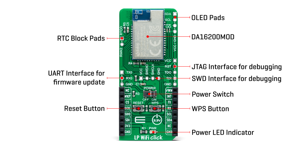
The DA16200MOD has an integrated RTC block (36-bit real-time counter), with a 32.768kHz clock source necessary for the free-running counter in the RTC block of the SoC, which provides power management and function control for low power operation. The RTC block is always powered ON when an onboard switch labeled as POWER is set to the appropriate ON position during normal operation, which optimizes power consumption and is used for power ON/OFF purposes. Also, the upper left header of the board, labeled as RTC Block Pads, is connected to the internal RTC block to connect and receive external event signals from an external device like a sensor.
The LP WiFi Click Board™ communicates with MCU using the UART interface as its default communication protocol. Users can use other interfaces such as SPI and I2C to improve and communicate with peripherals. It should be noted that the DA16200 module comes with firmware that only supports UART communication with the host microcontroller, and I2C with peripherals such as sensors (SPI interface is not supported by default and can be enabled by firmware update).
Additional options that this board has are certain buttons and headers. The onboard pushbuttons are labeled as RESET, and WPS represents a Factory reset button and WiFi Protected Setup (WPS) button. As for the headers, the first one marked with TX and RX signals is suitable for debugging purposes using the UART interface, while the second lets you add a small but bright and crisp OLED display to your design by connecting it on the upper-right header with I2C signals suitable for controlling the OLED.
This Click board™ can be operated only with a 3.3V logic voltage level. The board must perform appropriate logic voltage level conversion before use with MCUs with different logic levels. However, the Click board™ comes equipped with a library containing functions and an example code that can be used, as a reference, for further development.
The LP WiFi Click Board™ is coming already programmed with the default AT command firmware based on the Dialog Semiconductor FreeRTOS SDK. Developers interested in creating and loading custom firmware on the DA16200 can do so by using the UART_0 interface (J3 header) available on the left side for module programming. For debugging your custom firmware you can use either JTAG (J1 header) or the SWD (J2 header) debugging interfaces.
The DA16200 is a highly integrated ultra-low power Wi-Fi system on chip (SoC) that allows users to develop the Wi-Fi solution and store application on a single chip, that way creating a standalone device without any additional microcontroller needed.
To get started with development first you should learn how to setup development environment for the DA16200 SDK, you can do that by reading DA16200 FreeRTOS SDK Startup Guide. After that, you are ready to start development / customization relying on the document describing the SDK API with the peripheral device drivers and interfaces, called FreeRTOS SDK Programmer Guide.
For all additional questions and support for firmware customization as well as application development, users can contact the official Technical Support of Dialog Semiconductor.
| Type | WiFi |
| Applications | Can be used for highly integrated and cost-effective IoT applications such as security systems, door locks, pet and asset trackers, sprinkler systems, connected lighting, wearables, and other IoT devices |
| On-board modules | DA16200MOD-AAC4WA32 - highly integrated ultra low power Wi-Fi module from Dialog Semiconductor |
| Key Features | Ultra low power consumption, best RF performance, full offload, integrated chip antenna, various interfaces, WiFi alliance certifications, advanced security, battery life extension, and more |
| Interface | GPIO,I2C,SPI,UART |
| Compatibility | mikroBUS |
| Click board size | L (57.15 x 25.4 mm) |
| Input Voltage | 3.3V |
This table shows how the pinout on LP WiFi Click corresponds to the pinout on the mikroBUS™ socket (the latter shown in the two middle columns).
| Notes | Pin | Pin | Notes | ||||
|---|---|---|---|---|---|---|---|
| NC | 1 | AN | PWM | 16 | PWM | PWM Signal | |
| Wake-Up | WKP | 2 | RST | INT | 15 | INT | Interrupt |
| SPI Chip Select | CS | 3 | CS | RX | 14 | TX | UART TX |
| SPI Clock | SCK | 4 | SCK | TX | 13 | RX | UART RX |
| SPI Data OUT | SDO | 5 | MISO | SCL | 12 | SCL | I2C Clock |
| SPI Data IN | SDI | 6 | MOSI | SDA | 11 | SDA | I2C Data |
| Power Supply | 3.3V | 7 | 3.3V | 5V | 10 | NC | |
| Ground | GND | 8 | GND | GND | 9 | GND | Ground |
| Label | Name | Default | Description |
|---|---|---|---|
| LD1 | PWR | - | Power LED Indicator |
| SW1 | POWER | Left | Power Switch |
| J1 | - | Unpopulated | JTAG Interface for debugging |
| J2 | - | Unpopulated | SWD Interface for debugging |
| J3 | - | Unpopulated | UART Interface for firmware update |
| J4 | - | Unpopulated | RTC Block Header |
| J5 | - | Unpopulated | OLED Header |
| T1 | WPS | - | WiFi Protected Setup (WPS) Button |
| T2 | RESET | - | Factory Reset Button |
| Description | Min | Typ | Max | Unit |
|---|---|---|---|---|
| Supply Voltage | - | 3.3 | - | V |
| Operating Frequency Range | - | 2.4 | - | GHz |
| RF Performance: TX Power | - | >+20 | - | dBm |
| RF Performance: RX Sensitivity | - | >-100 | - | dBm |
| Current Consumption in Active State (TX) | - | 200 - 280 | - | mA |
| Current Consumption in Active State (RX) | - | 28.1 - 37.4 | - | mA |
| Current Consumption in Low Power State | - | 0.2 | - | uA |
| Operating Temperature Range | -40 | +25 | +85 | °C |
We provide a library for the LP WiFi Click Board™ as well as a demo application (example), developed using MikroElektronika compilers. The demo can run on all the main MikroElektronika development boards.
Package can be downloaded/installed directly from NECTO Studio Package Manager(recommended way), downloaded from our LibStock™ or found on Mikroe Github account.
This library contains API for LP WiFi Click driver.
lpwifi_cfg_setup - Config Object Initialization function.lpwifi_init - Initialization function.lpwifi_default_cfg - Click Default Configuration function.This example reads and processes data from the LP WiFi Click Board™.
void application_task ( void )
{
    lpwifi_process( );
    lpwifi_log_app_buf( );
}
The full application code, and ready to use projects can be installed directly from NECTO Studio Package Manager(recommended way), downloaded from our LibStock™ or found on Mikroe github account.
Other Mikroe Libraries used in the example:
Depending on the development board you are using, you may need USB UART click, USB UART 2 click or RS232 click to connect to your PC, for development systems with no UART to USB interface available on the board. The terminal available in all MikroElektronika compilers, or any other terminal application of your choice, can be used to read the message.
The LP WiFi Click Board™ is supported with mikroSDK - MikroElektronika Software Development Kit. To ensure proper operation of mikroSDK compliant Click board™ demo applications, mikroSDK should be downloaded from the LibStock and installed for the compiler you are using.
- manufacturer: Mikroelektronika d.o.o. - warranty: 12 months - mpn: MIKROE-4836 - backorder_label: If no stock shown above, check availability - attachments: [{"download_file":[{"download_file":"LP WiFi Click Board™ Schematic"}],"download_filetype":[{"download_filetype":"pdf"}]},{"download_file":[{"download_file":"Dialog Semiconductor DA16200MOD-AA Ultra-Low-Power WiFi Module Datasheet"}],"download_filetype":[{"download_filetype":"pdf"}]}] - condition: new - custom_product: false - mpn: MIKROE-4836 - google_product_category: Electronics - custom_label_0: Click Board - myordercount: {"ordercount":1,"recentcount":1} - device_vendor: Dialog Semiconductor GmbH - device_type: DA16200MOD-AAC4WA32 - warranty: 12 months - brand: MikroE - manufacturer: Mikroelektronika d.o.o. - target_keyword: LP WiFi Click Board - brands: gid://shopify/Metaobject/56256004319 - breadcrumbs: ["gid://shopify/Collection/447955239135","gid://shopify/Collection/241680580797","gid://shopify/Collection/241546166461"] - customhs_code: 847330 - detailed_description: {"type":"root","children":[{"type":"heading","level":3,"children":[{"type":"text","value":"How Does The LP WiFi Click Board™ Work?"}]},{"type":"paragraph","children":[{"type":"text","value":"The"},{"type":"text","value":" LP WiFi Click Board™","bold":true,"italic":true},{"type":"text","value":" as its foundation uses the DA16200MOD-AA, a highly integrated ultra low power Wi-Fi module with the best RF performance and a comfortable development environment from Dialog Semiconductor. It consists of the DA16200 SoC, 4MB flash memory, RF components including a crystal oscillator, RF lumped filter and an onboard 2.4GHz chip antenna. Such low power operation can extend the battery life for a year or more, depending on the application, even when the board is continuously connected to the Wi-Fi network. This module also features strong IoT security, including WPA3 and TLS for authentication and encryption at Wi-Fi and higher stack layers."}]},{"type":"paragraph","children":[{"type":"text","value":""}]},{"type":"paragraph","children":[{"type":"text","value":"The DA16200MOD has an integrated RTC block (36-bit real-time counter), with a 32.768kHz clock source necessary for the free-running counter in the RTC block of the SoC, which provides power management and function control for low power operation. The RTC block is always powered ON when an onboard switch labeled as POWER is set to the appropriate ON position during normal operation, which optimizes power consumption and is used for power ON/OFF purposes. Also, the upper left header of the board, labeled as RTC Block Pads, is connected to the internal RTC block to connect and receive external event signals from an external device like a sensor."}]},{"type":"paragraph","children":[{"type":"text","value":"The"},{"type":"text","value":" LP WiFi Click Board™","bold":true},{"type":"text","value":" communicates with MCU using the UART interface as its default communication protocol. Users can use other interfaces such as SPI and I2C to improve and communicate with peripherals. It should be noted that the DA16200 module comes with firmware that only supports UART communication with the host microcontroller, and I2C with peripherals such as sensors (SPI interface is not supported by default and can be enabled by firmware update)."}]},{"type":"paragraph","children":[{"type":"text","value":"Additional options that this board has are certain buttons and headers. The onboard pushbuttons are labeled as RESET, and WPS represents a Factory reset button and WiFi Protected Setup (WPS) button. As for the headers, the first one marked with TX and RX signals is suitable for debugging purposes using the UART interface, while the second lets you add a small but bright and crisp OLED display to your design by connecting it on the upper-right header with I2C signals suitable for controlling the OLED."}]},{"type":"paragraph","children":[{"type":"text","value":"This Click board™ can be operated only with a 3.3V logic voltage level. The board must perform appropriate logic voltage level conversion before use with MCUs with different logic levels. However, the Click board™ comes equipped with a library containing functions and an example code that can be used, as a reference, for further development."}]},{"type":"heading","level":3,"children":[{"type":"text","value":"Dialog SDK and support"}]},{"type":"paragraph","children":[{"type":"text","value":"The "},{"type":"text","value":"LP WiFi Click Board™","bold":true},{"type":"text","value":" is coming already programmed with the default AT command firmware based on the Dialog Semiconductor FreeRTOS SDK. Developers interested in creating and loading custom firmware on the DA16200 can do so by using the UART_0 interface (J3 header) available on the left side for module programming. For debugging your custom firmware you can use either JTAG (J1 header) or the SWD (J2 header) debugging interfaces."}]},{"type":"paragraph","children":[{"type":"text","value":"The DA16200 is a highly integrated ultra-low power Wi-Fi system on chip (SoC) that allows users to develop the Wi-Fi solution and store application on a single chip, that way creating a standalone device without any additional microcontroller needed."}]},{"type":"paragraph","children":[{"type":"text","value":"To get started with development first you should learn how to setup development environment for the DA16200 SDK, you can do that by reading DA16200 FreeRTOS SDK Startup Guide. After that, you are ready to start development / customization relying on the document describing the SDK API with the peripheral device drivers and interfaces, called FreeRTOS SDK Programmer Guide."}]},{"type":"paragraph","children":[{"type":"text","value":"For all additional questions and support for firmware customization as well as application development, users can contact the official Technical Support of Dialog Semiconductor."}]},{"type":"heading","level":3,"children":[{"type":"text","value":"Specifications"}]},{"type":"paragraph","children":[{"type":"text","value":"Type\nWiFi\nApplications\nCan be used for highly integrated and cost-effective IoT applications such as security systems, door locks, pet and asset trackers, sprinkler systems, connected lighting, wearables, and other IoT devices\nOn-board modules\nDA16200MOD-AAC4WA32 - highly integrated ultra low power Wi-Fi module from Dialog Semiconductor\nKey Features\nUltra low power consumption, best RF performance, full offload, integrated chip antenna, various interfaces, WiFi alliance certifications, advanced security, battery life extension, and more\nInterface\nGPIO,I2C,SPI,UART\nCompatibility\nmikroBUS\nClick board size\nL (57.15 x 25.4 mm)\nInput Voltage\n3.3V"}]},{"type":"heading","level":3,"children":[{"type":"text","value":"Pinout diagram"}]},{"type":"paragraph","children":[{"type":"text","value":"This table shows how the pinout on LP WiFi Click corresponds to the pinout on the mikroBUS™ socket (the latter shown in the two middle columns)."}]},{"type":"paragraph","children":[{"type":"text","value":"Notes\nPin\nPin\nNotes\nNC\n1\nAN\nPWM\n16\nPWM\nPWM Signal\nWake-Up\nWKP\n2\nRST\nINT\n15\nINT\nInterrupt\nSPI Chip Select\nCS\n3\nCS\nRX\n14\nTX\nUART TX\nSPI Clock\nSCK\n4\nSCK\nTX\n13\nRX\nUART RX\nSPI Data OUT\nSDO\n5\nMISO\nSCL\n12\nSCL\nI2C Clock\nSPI Data IN\nSDI\n6\nMOSI\nSDA\n11\nSDA\nI2C Data\nPower Supply\n3.3V\n7\n3.3V\n5V\n10\nNC\nGround\nGND\n8\nGND\nGND\n9\nGND\nGround"}]},{"type":"heading","level":3,"children":[{"type":"text","value":"Onboard settings and indicators"}]},{"type":"paragraph","children":[{"type":"text","value":"Label\nName\nDefault\n Description\nLD1\nPWR\n-\nPower LED Indicator\nSW1\nPOWER\nLeft\nPower Switch\nJ1\n-\nUnpopulated\nJTAG Interface for debugging\nJ2\n-\nUnpopulated\nSWD Interface for debugging\nJ3\n-\nUnpopulated\nUART Interface for firmware update\nJ4\n-\nUnpopulated\nRTC Block Header\nJ5\n-\nUnpopulated\nOLED Header\nT1\nWPS\n-\nWiFi Protected Setup (WPS) Button\nT2\nRESET\n-\nFactory Reset Button"}]},{"type":"heading","level":3,"children":[{"type":"text","value":"LP WiFi Click electrical specifications"}]},{"type":"paragraph","children":[{"type":"text","value":"Description\nMin\nTyp\nMax\nUnit\nSupply Voltage\n-\n3.3\n-\nV\nOperating Frequency Range\n-\n2.4\n-\nGHz\nRF Performance: TX Power\n-\n>+20\n-\ndBm\nRF Performance: RX Sensitivity\n-\n>-100\n-\ndBm\nCurrent Consumption in Active State (TX)\n-\n200 - 280\n-\nmA\nCurrent Consumption in Active State (RX)\n-\n28.1 - 37.4\n-\nmA\nCurrent Consumption in Low Power State\n-\n0.2\n-\nuA\nOperating Temperature Range\n-40\n+25\n+85\n°C"}]},{"type":"heading","level":3,"children":[{"type":"text","value":" "}]}]} - summary:The LP WiFi Click Board™ is a compact add-on board that represents an ultra-low-power Wi-Fi solution. This board features the DA16200, a fully integrated Wi-Fi module with ultra-low power consumption, best RF performance, and a comfortable development environment from Dialog Semiconductor. In addition to the highly integrated ultra-low power Wi-Fi SoC, which is the basis of this module, it also includes a 40MHz crystal oscillator, 32.768kHz RTC clock, 4Mbyte flash memory, and chip antenna. Such low power operation can extend the battery life as long as a year or more, depending on the application. This Click Board™ is suitable for highly integrated and cost-effective IoT applications such as security systems, door locks, pet and asset trackers, sprinkler systems, connected lighting, wearables, and other IoT devices.
The LP WiFi Click Board™ is supported by a mikroSDK compliant library, which includes functions that simplify software development. This Click Board™ comes as a fully tested product, ready to be used on a system equipped with the mikroBUS™ socket.