The Fan 8 Click Board™ as its foundation uses the MAX6615, a compliant fan controller, and accurately two temperature-channels monitors from Maxim Integrated, now part of Analog Devices. The MAX6615 monitors either the internal die temperature and the temperature of external thermistors connected on the onboard headers labeled as TH and reports temperature values in digital form using a 2-wire serial interface. To adjust the speed of the cooling fans, the temperature data controls the duty cycle of a PWM output signal, which minimizes noise when the system is running cool but provides maximum cooling when power dissipation increases.
The Fan 8 Click Board™ communicates with MCU using the standard I2C 2-Wire interface to read data and configure settings with a maximum frequency of 400kHz. Besides, it also allows the choice of the least significant bit of its I2C slave address by positioning the SMD jumpers labeled as ADDR SEL to an appropriate position marked as 0 and 1. This way, the MAX6616 provides the opportunity of the nine possible different I2C addresses by positioning the SMD jumper to an appropriate position.
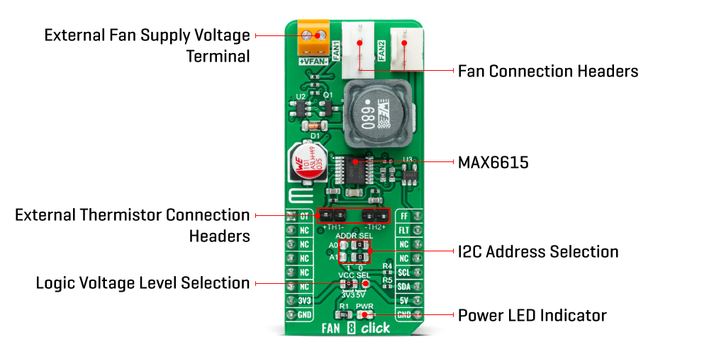
The MAX6615 monitors the fans' tachometer signals to detect fan failure. When the fan tachometer count is larger than the fan tachometer limit, the fan is considered failing. If that happens, the FAN_FAIL output represented by the FF pin, routed on the PWM pin of the mikroBUS™ socket, is asserted. Also, the MAX6615 features an over-temperature indicator routed on the AN pin of the mikroBUS™ socket, which sets high when a thermal fault occurs and can be used as a warning flag to initiate the system shutdown or to throttle clock frequency. In the event of any of these irregularities, the MCU will also receive information from an FLT pin (fault indicator), routed on the INT pin of the mikroBUS™ socket, in case of further necessary configurations necessary for proper operation.
The Fan 8 Click Board™k supports an external fan power supply, connected to the input terminal labeled as VFAN with the value of 5V or 12V, while the fan connection wires can be connected to the onboard headers labeled as FAN1 and FAN2.
This Click board™ can operate with both 3.3V and 5V logic voltage levels selected via the VCC SEL jumper. This way, it is allowed for both 3.3V and 5V capable MCUs to use the I2C communication lines properly. However, the Click board™ comes equipped with a library containing easy-to-use functions and an example code that can be used, as a reference, for further development.
| Type | Brushless |
| Applications | Can be used for networking equipment, servers, or other applications requiring cooling and temperature control |
| On-board modules | MAX6615 - compliant fan controller, and accurately two temperature-channels monitors from Maxim Integrated, now part of Analog Devices |
| Key Features | Two fan-speed controller, dual-channel temperature monitor, external thermistors, fail-safe system protection, shutdown in case of overtemperature, programmable I2C addresses, and more |
| Interface | I2C |
| Compatibility | mikroBUS |
| Click board size | L (57.15 x 25.4 mm) |
| Input Voltage | 3.3V or 5V,External |
This table shows how the pinout on the Fan 8 Click Board™ corresponds to the pinout on the mikroBUS™ socket (the latter shown in the two middle columns).
| Notes | Pin | Pin | Notes | ||||
|---|---|---|---|---|---|---|---|
| Overtemperature Indicator | OT | 1 | AN | PWM | 16 | FF | Fan-Fail Indicator |
| NC | 2 | RST | INT | 15 | FLT | Fault Indicator | |
| NC | 3 | CS | RX | 14 | NC | ||
| NC | 4 | SCK | TX | 13 | NC | ||
| NC | 5 | MISO | SCL | 12 | SCL | I2C Clock | |
| NC | 6 | MOSI | SDA | 11 | SDA | I2C Data | |
| Power Supply | 3.3V | 7 | 3.3V | 5V | 10 | 5V | Power Supply |
| Ground | GND | 8 | GND | GND | 9 | GND | Ground |
| Label | Name | Default | Description |
|---|---|---|---|
| LD1 | PWR | - | Power LED Indicator |
| JP1-JP2 | ADDR SEL | Right | I2C Address Selection 0/1: Left position 0, Right position 1 |
| JP3 | VCC SEL | Left | Logic Level Voltage Selection 3V3/5V: Left position 3V3, Right position 5V |
| TH1-TH2 | TH1-TH2 | Populated | External Thermistor Connection Headers |
| J1-J2 | FAN1-FAN2 | Populated | Fan Connection Headers |
| Description | Min | Typ | Max | Unit |
|---|---|---|---|---|
| Supply Voltage VCC | 3.3 | - | 5 | V |
| Fan Supply Voltage VFAN | - | 5 (12) | - | V |
| Accuracy | - | - | ±4 | °C |
| Operating Temperature Range | -40 | +25 | +125 | °C |
We provide a library for the Fan 8 Click Board™ as well as a demo application (example), developed using MikroElektronika compilers. The demo can run on all the main MikroElektronika development boards.
The package can be downloaded/installed directly from NECTO Studio Package Manager(recommended way), downloaded from our LibStock™ or found on Mikroe Github account.
This library contains API for the Fan 8 Click Board™ driver.
fan8_set_duty_cycle - This function sets the duty cycle of the selected fan channel and waits until the duty cycle is set at the PWM output.fan8_measure_rpm - This function measures the RPM of the selected fan channel.fan8_read_temperature - This function reads the temperature from the thermistor attached to the selected temperature channel.This example demonstrates the use of the Fan 8 Click Board™.
void application_task ( void )
{
    static uint8_t duty_cnt = FAN8_MIN_DUTY_CYCLE;
    static int8_t duty_inc = FAN8_DUTY_CYCLE_STEP_10;
    uint16_t fan_rpm = 0;
    float temperature = 0;

    if ( duty_cnt == FAN8_MAX_DUTY_CYCLE )
    {
        duty_inc = -FAN8_DUTY_CYCLE_STEP_10;
    }
    else if ( duty_cnt == ( FAN8_MIN_DUTY_CYCLE + FAN8_DUTY_CYCLE_STEP_10 ) )
    {
        duty_inc = FAN8_DUTY_CYCLE_STEP_10;
    }
    duty_cnt += duty_inc;

    log_printf( &logger, " - Channel 1 values -rn" );
    fan8_set_duty_cycle ( &fan8, FAN8_FAN_CHANNEL_1, duty_cnt );
    log_printf( &logger, " PWM Duty Cycle : %drn", ( uint16_t ) duty_cnt );
    fan8_measure_rpm ( &fan8, FAN8_FAN_CHANNEL_1, FAN8_2_PULSES_PER_REVOLUTION, &fan_rpm );
    log_printf( &logger, " Last measured fan RPM : %urn", fan_rpm );
    fan8_read_temperature ( &fan8, FAN8_TEMP_CHANNEL_1, &temperature );
    log_printf( &logger, " Temperature : %.2f Crnrn", temperature );

    log_printf( &logger, " - Channel 2 values -rn" );
    fan8_set_duty_cycle ( &fan8, FAN8_FAN_CHANNEL_2, duty_cnt );
    log_printf( &logger, " PWM Duty Cycle : %drn", ( uint16_t ) duty_cnt );
    fan8_measure_rpm ( &fan8, FAN8_FAN_CHANNEL_2, FAN8_2_PULSES_PER_REVOLUTION, &fan_rpm );
    log_printf( &logger, " Last measured fan RPM : %urn", fan_rpm );
    fan8_read_temperature ( &fan8, FAN8_TEMP_CHANNEL_2, &temperature );
    log_printf( &logger, " Temperature : %.2f Crnrn", temperature );

    if ( !fan8_check_fault_indicator ( &fan8 ) )
    {
        log_printf( &logger, " Fault detected!rnrn", temperature );
    }

    Delay_ms( 500 );
}
The full application code, and ready to use projects can be installed directly from NECTO Studio Package Manager(recommended way), downloaded from our LibStock™ or found on Mikroe Github account.
Other mikroE Libraries used in the example:
Depending on the development board you are using, you may need a USB UART click, USB UART 2 click or RS232 click to connect to your PC, for development systems with no UART to USB interface available on the board. The terminal available in all MikroElektronika compilers, or any other terminal application of your choice, can be used to read the message.
The Fan 8 Click Board™ is supported with mikroSDK - MikroElektronika Software Development Kit. To ensure proper operation of mikroSDK compliant Click board™ demo applications, mikroSDK should be downloaded from the LibStock and installed for the compiler you are using.
- attachments: [{"download_file":[{"download_file":"Fan 8 Click Board™ Schematic"}],"download_filetype":[{"download_filetype":"pdf"}]},{"download_file":[{"download_file":"Analog Devices MAX6615 Fan Speed Controller Datasheet"}],"download_filetype":[{"download_filetype":"pdf"}]}] - manufacturer: Mikroelektronika d.o.o. - warranty: 12 months - backorder_label: If no stock shown above, check availability - condition: new - custom_product: false - mpn: MIKROE-4824 - google_product_category: Electronics - custom_label_0: Click Board - mpn: MIKROE-4824 - device_vendor: Maxim Integrated, Microchip Technology - device_type: MAX6615AEE+, MCP1401T-E/OT - warranty: 12 months - brand: MikroE - manufacturer: Mikroelektronika d.o.o. - target_keyword: Fan 8 Click Board - brands: gid://shopify/Metaobject/56256004319 - breadcrumbs: ["gid://shopify/Collection/447955239135","gid://shopify/Collection/241680580797","gid://shopify/Collection/241545248957","gid://shopify/Collection/279405199549"] - customhs_code: 847330 - detailed_description: {"type":"root","children":[{"type":"heading","level":3,"children":[{"type":"text","value":"How Does The Fan 8 Click Board™ Work?"}]},{"type":"paragraph","children":[{"type":"text","value":"The "},{"type":"text","value":"Fan 8 Click Board™","bold":true,"italic":true},{"type":"text","value":" as its foundation uses the MAX6615, a compliant fan controller, and accurately two temperature-channels monitors from Maxim Integrated, now part of Analog Devices. The MAX6615 monitors either the internal die temperature and the temperature of external thermistors connected on the onboard headers labeled as TH and reports temperature values in digital form using a 2-wire serial interface. To adjust the speed of the cooling fans, the temperature data controls the duty cycle of a PWM output signal, which minimizes noise when the system is running cool but provides maximum cooling when power dissipation increases."}]},{"type":"paragraph","children":[{"type":"text","value":""}]},{"type":"paragraph","children":[{"type":"text","value":"The "},{"type":"text","value":"Fan 8 Click Board™","bold":true},{"type":"text","value":" communicates with MCU using the standard I2C 2-Wire interface to read data and configure settings with a maximum frequency of 400kHz. Besides, it also allows the choice of the least significant bit of its I2C slave address by positioning the SMD jumpers labeled as ADDR SEL to an appropriate position marked as 0 and 1. This way, the MAX6616 provides the opportunity of the nine possible different I2C addresses by positioning the SMD jumper to an appropriate position."}]},{"type":"paragraph","children":[{"type":"text","value":"The MAX6615 monitors the fans' tachometer signals to detect fan failure. When the fan tachometer count is larger than the fan tachometer limit, the fan is considered failing. If that happens, the FAN_FAIL output represented by the FF pin, routed on the PWM pin of the mikroBUS™ socket, is asserted. Also, the MAX6615 features an over-temperature indicator routed on the AN pin of the mikroBUS™ socket, which sets high when a thermal fault occurs and can be used as a warning flag to initiate the system shutdown or to throttle clock frequency. In the event of any of these irregularities, the MCU will also receive information from an FLT pin (fault indicator), routed on the INT pin of the mikroBUS™ socket, in case of further necessary configurations necessary for proper operation."}]},{"type":"paragraph","children":[{"type":"text","value":"The "},{"type":"text","value":"Fan 8 Click Board™","bold":true},{"type":"text","value":"k supports an external fan power supply, connected to the input terminal labeled as VFAN with the value of 5V or 12V, while the fan connection wires can be connected to the onboard headers labeled as FAN1 and FAN2."}]},{"type":"paragraph","children":[{"type":"text","value":"This Click board™ can operate with both 3.3V and 5V logic voltage levels selected via the VCC SEL jumper. This way, it is allowed for both 3.3V and 5V capable MCUs to use the I2C communication lines properly. However, the Click board™ comes equipped with a library containing easy-to-use functions and an example code that can be used, as a reference, for further development."}]},{"type":"heading","level":3,"children":[{"type":"text","value":"Specifications"}]},{"type":"paragraph","children":[{"type":"text","value":"Type\nBrushless\nApplications\nCan be used for networking equipment, servers, or other applications requiring cooling and temperature control\nOn-board modules\nMAX6615 - compliant fan controller, and accurately two temperature-channels monitors from Maxim Integrated, now part of Analog Devices\nKey Features\nTwo fan-speed controller, dual-channel temperature monitor, external thermistors, fail-safe system protection, shutdown in case of overtemperature, programmable I2C addresses, and more\nInterface\nI2C\nCompatibility\nmikroBUS\nClick board size\nL (57.15 x 25.4 mm)\nInput Voltage\n3.3V or 5V,External"}]},{"type":"heading","level":3,"children":[{"type":"text","value":"Pinout diagram"}]},{"type":"paragraph","children":[{"type":"text","value":"This table shows how the pinout on the "},{"type":"text","value":"Fan 8 Click Board™","bold":true},{"type":"text","value":" corresponds to the pinout on the mikroBUS™ socket (the latter shown in the two middle columns)."}]},{"type":"paragraph","children":[{"type":"text","value":"Notes\nPin\nPin\nNotes\nOvertemperature Indicator\nOT\n1\nAN\nPWM\n16\nFF\nFan-Fail Indicator\nNC\n2\nRST\nINT\n15\nFLT\nFault Indicator\nNC\n3\nCS\nRX\n14\nNC\nNC\n4\nSCK\nTX\n13\nNC\nNC\n5\nMISO\nSCL\n12\nSCL\nI2C Clock\nNC\n6\nMOSI\nSDA\n11\nSDA\nI2C Data\nPower Supply\n3.3V\n7\n3.3V\n5V\n10\n5V\nPower Supply\nGround\nGND\n8\nGND\nGND\n9\nGND\nGround"}]},{"type":"heading","level":3,"children":[{"type":"text","value":"Onboard settings and indicators"}]},{"type":"paragraph","children":[{"type":"text","value":"Label\nName\nDefault\n Description\nLD1\nPWR\n-\nPower LED Indicator\nJP1-JP2\nADDR SEL\nRight\nI2C Address Selection 0/1: Left position 0, Right position 1\nJP3\nVCC SEL\nLeft\nLogic Level Voltage Selection 3V3/5V: Left position 3V3, Right position 5V\nTH1-TH2\nTH1-TH2\nPopulated\nExternal Thermistor Connection Headers\nJ1-J2\nFAN1-FAN2\nPopulated\nFan Connection Headers"}]},{"type":"heading","level":3,"children":[{"type":"text","value":"Fan 8 Click electrical specifications"}]},{"type":"paragraph","children":[{"type":"text","value":"Description\nMin\nTyp\nMax\nUnit\nSupply Voltage VCC\n3.3\n-\n5\nV\nFan Supply Voltage VFAN\n-\n5 (12)\n-\nV\nAccuracy\n-\n-\n±4\n°C\nOperating Temperature Range\n-40\n+25\n+125\n°C"}]},{"type":"heading","level":3,"children":[{"type":"text","value":" "}]}]} - summary:The Fan 8 Click Board™ is a compact add-on board that represents a compliant fan controller. This board features the MAX6615, a fan-speed controller, and a dual-channel temperature monitor with external thermistor inputs from Maxim Integrated, now part of Analog Devices. The MAX6615 controls the speed of two cooling fans based on the temperatures of external thermistors and the device's internal temperature, reporting temperature values in a digital form using the I2C serial interface. The temperature data controls a PWM output signal to adjust the speed of a cooling fan, minimizing noise when the system is running cool, but providing maximum cooling when power dissipation increases.
It also features an overtemperature alarm to generate interrupts, throttle, or shutdown signals. The combination of high accuracy and dual thermistor inputs makes this Click board a practical choice for networking equipment, servers, or other applications requiring cooling and temperature control.