The DC Motor 18 Click Board™ as its foundation uses the TB9051FTG, a motor driver which incorporates the output driver for the direct drive of a DC brushed motor intended for automotive use from Toshiba Semiconductor. While primarily targeting vehicle engine applications, such as electronic throttle and valve control, the TB9051FTG can also be suitable for controlling onboard systems operating at up to 5A, such as control of wing mirrors and trunk locks. Control functions include motor-related (forward, reverse, brake), PWM control, current limit control, H-side current monitor, diagnosis output, and built-in detection circuits for overcurrent, overheat, and low/high voltage.
The DC Motor 18 Click Board™ communicates with MCU using several GPIO pins. The Enable pin, labeled as EN and routed to the CS pin of the mikroBUS™ socket, optimizes power consumption and is used for power ON/OFF purposes (driver operation permission). The Forward/Reverse/Brake mode can be selected according to PWM control signals routed to the PWN and RST pins of the mikroBUS™ socket.
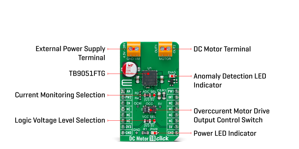
The current, which flows to the high side in the H-bridge of motor-driven output, is monitored in real-time, where the user can select the way of the current monitoring. In the case of a 5V VCC power supply, the current can be monitored using the AN pin on the mikroBUS™ socket, and in the case of a lesser power supply (3.3V), monitoring is possible with the help of an added voltage divider between the OCM pin and GND. Selection can be performed by onboard SMD jumper labelled as ADC SEL.
This Click board™ also has an additional LED for anomaly indication. Suppose a state such as an overtemperature or overcurrent/under voltage is detected. In that case, such anomaly is indicated by a red LED marked as DIAG, which is also connected to the interrupt INT pin through which the user can also monitor the state of the diagnostic pin. In addition, there is the possibility of controlling the motor control output at the time of the overcurrent detection, which is realized through an onboard switch labelled as OCC. This switch is used for the judgment of whether the motor control output is ON(1) or OFF(0).
The DC Motor 18 Click Board™ supports an external power supply for the TB9051FTG, which can be connected to the input terminal labelled as VM and should be within the range of 4.5V to 28V, while the DC motor coils can be connected to the terminals labelled as OUT1 and OUT2.
This Click board™ can operate with both 3.3V and 5V logic voltage levels selected via the VCC SEL jumper. This way, it is allowed for both 3.3V and 5V capable MCUs to use communication lines properly. However, the Click board™ comes equipped with a library containing easy-to-use functions and an example code that can be used, as a reference, for further development.
| Type | Brushed |
| Applications | Can be used for various automotive applications such as throttle and valve control, various engine bulbs, storing of door mirrors, and seat positioning |
| On-board modules | TB9051FTG - motor driver which incorporates the output driver for the direct drive of a DC brushed motor intended for automotive use from Toshiba Semiconductor |
| Key Features | Key Features Low power consumption, ultra low on-resistance, anomaly detection features, selectable motor operation, PWM control, high-side current monitoring, diagnosis indicator, and more. |
| Interface | Analog,GPIO,PWM |
| Compatibility | mikroBUS |
| Click board size | M (42.9 x 25.4 mm) |
| Input Voltage | 3.3V or 5V |
This table shows how the pinout on DC Motor 18 Click corresponds to the pinout on the mikroBUS™ socket (the latter shown in the two middle columns).
| Notes | Pin | Pin | Notes | ||||
|---|---|---|---|---|---|---|---|
| Analog Signal | AN | 1 | AN | PWM | 16 | PW1 | Driver Control Signal 1 |
| Driver Control Signal 2 | PW2 | 2 | RST | INT | 15 | INT | Interrupt |
| Driver Enable | EN | 3 | CS | RX | 14 | NC | |
| NC | 4 | SCK | TX | 13 | NC | ||
| NC | 5 | MISO | SCL | 12 | NC | ||
| NC | 6 | MOSI | SDA | 11 | NC | ||
| Power Supply | 3.3V | 7 | 3.3V | 5V | 10 | 5V | Power Supply |
| Ground | GND | 8 | GND | GND | 9 | GND | Ground |
| Label | Name | Default | Description |
|---|---|---|---|
| LD1 | PWR | - | Power LED Indicator |
| LD2 | DIAG | - | Anomaly Detection LED Indicator |
| JP1 | VCC SEL | Left | Logic Level Voltage Selection 3V3/5V: Left position 3V3, Right position 5V |
| JP2 | ADC SEL | Left | Current Monitoring Selection 3V3/5V: Left position 3V3, Right position 5V |
| SW1 | OCC | Left | Overcurrent Motor Drive Output Control Switch |
| Description | Min | Typ | Max | Unit |
|---|---|---|---|---|
| Supply Voltage | 3.3 | - | 5 | V |
| External Power Supply VM | 45 | - | 28 | V |
| Maximum Output Current | - | - | 5 | A |
| Operating Temperature Range | -40 | +25 | +125 | °C |
We provide a library for the DC Motor 18 Click as well as a demo application (example), developed using MikroElektronika compilers. The demo can run on all the main MikroElektronika development boards.
The package can be downloaded/installed directly from NECTO Studio Package Manager(recommended way), downloaded from our LibStock™ or found on Mikroe GitHub account.
This library contains API for DC Motor 18 Click driver.
dcmotor18_cfg_setup - Config Object Initialization function.dcmotor18_init - Initialization function.dcmotor18_default_cfg - Click Default Configuration function.This example application showcases the ability of click board to control DC motors using PWM modulation in both directions and different speeds.
void application_task ( void )
{
    static int8_t duty_cnt = 1;
    static int8_t duty_inc = 1;
    float speed = duty_cnt / 10.0;
    static uint8_t direction = 1;

    dcmotor18_set_direction( &dcmotor18, direction );
    dcmotor18_set_speed_percentage ( &dcmotor18, speed );

    if ( dcmotor18.direction )
    {
        log_printf( &logger, "<<< " );
    }
    else
    {
        log_printf( &logger, ">>> " );
    }
    log_printf( &logger, "Speed: %d%%rn", ( uint16_t )( duty_cnt * 10 ) );

    if ( 10 == duty_cnt )
    {
        duty_inc = -1;
    }
    else if ( 0 == duty_cnt )
    {
        duty_inc = 1;
        direction = !direction;
    }
    duty_cnt += duty_inc;

    Delay_ms( 1000 );
}
The full application code, and ready to use projects can be installed directly from NECTO Studio Package Manager(recommended way), downloaded from our LibStock™ or found on Mikroe GitHub account.
Other mikroE Libraries used in the example:
Depending on the development board you are using, you may need a USB UART click, USB UART 2 click or RS232 click to connect to your PC, for development systems with no UART to USB interface available on the board. The terminal available in all MikroElektronika compilers, or any other terminal application of your choice, can be used to read the message.
This Click board™ is supported with mikroSDK - MikroElektronika Software Development Kit. To ensure proper operation of mikroSDK compliant Click board™ demo applications, mikroSDK should be downloaded from the LibStock and installed for the compiler you are using.
- attachments: [{"download_file":[{"download_file":"DC Motor 18 Click Board™"}],"download_filetype":[{"download_filetype":"pdf"}]},{"download_file":[{"download_file":"Toshiba TB9051FTG Datasheet"}],"download_filetype":[{"download_filetype":"pdf"}]}] - condition: new - custom_product: false - mpn: MIKROE-4786 - google_product_category: Electronics - custom_label_0: Click Board - device_vendor: Toshiba Semiconductor and Storage - device_type: TB9051FTG,EL - warranty: 12 months - brand: MikroE - manufacturer: Mikroelektronika d.o.o. - target_keyword: DC Motor 18 Click Board - brands: gid://shopify/Metaobject/56256004319 - breadcrumbs: ["gid://shopify/Collection/447955239135","gid://shopify/Collection/241680580797","gid://shopify/Collection/241545248957","gid://shopify/Collection/279405134013"] - customhs_code: 847330 - detailed_description: {"type":"root","children":[{"type":"heading","level":3,"children":[{"type":"text","value":"How Does The DC Motor 18 Click Board™ Work?"}]},{"type":"paragraph","children":[{"type":"text","value":"The"},{"type":"text","value":" DC Motor 18 Click Board™","bold":true,"italic":true},{"type":"text","value":" as its foundation uses the TB9051FTG, a motor driver which incorporates the output driver for the direct drive of a DC brushed motor intended for automotive use from Toshiba Semiconductor. While primarily targeting vehicle engine applications, such as electronic throttle and valve control, the TB9051FTG can also be suitable for controlling onboard systems operating at up to 5A, such as control of wing mirrors and trunk locks. Control functions include motor-related (forward, reverse, brake), PWM control, current limit control, H-side current monitor, diagnosis output, and built-in detection circuits for overcurrent, overheat, and low/high voltage."}]},{"type":"paragraph","children":[{"type":"text","value":""}]},{"type":"paragraph","children":[{"type":"text","value":"The "},{"type":"text","value":"DC Motor 18 Click Board™","bold":true},{"type":"text","value":" communicates with MCU using several GPIO pins. The Enable pin, labeled as EN and routed to the CS pin of the mikroBUS™ socket, optimizes power consumption and is used for power ON/OFF purposes (driver operation permission). The Forward/Reverse/Brake mode can be selected according to PWM control signals routed to the PWN and RST pins of the mikroBUS™ socket."}]},{"type":"paragraph","children":[{"type":"text","value":"The current, which flows to the high side in the H-bridge of motor-driven output, is monitored in real-time, where the user can select the way of the current monitoring. In the case of a 5V VCC power supply, the current can be monitored using the AN pin on the mikroBUS™ socket, and in the case of a lesser power supply (3.3V), monitoring is possible with the help of an added voltage divider between the OCM pin and GND. Selection can be performed by onboard SMD jumper labelled as ADC SEL."}]},{"type":"paragraph","children":[{"type":"text","value":"This Click board™ also has an additional LED for anomaly indication. Suppose a state such as an overtemperature or overcurrent/under voltage is detected. In that case, such anomaly is indicated by a red LED marked as DIAG, which is also connected to the interrupt INT pin through which the user can also monitor the state of the diagnostic pin. In addition, there is the possibility of controlling the motor control output at the time of the overcurrent detection, which is realized through an onboard switch labelled as OCC. This switch is used for the judgment of whether the motor control output is ON(1) or OFF(0)."}]},{"type":"paragraph","children":[{"type":"text","value":"The "},{"type":"text","value":"DC Motor 18 Click Board™","bold":true},{"type":"text","value":" supports an external power supply for the TB9051FTG, which can be connected to the input terminal labelled as VM and should be within the range of 4.5V to 28V, while the DC motor coils can be connected to the terminals labelled as OUT1 and OUT2."}]},{"type":"paragraph","children":[{"type":"text","value":"This Click board™ can operate with both 3.3V and 5V logic voltage levels selected via the VCC SEL jumper. This way, it is allowed for both 3.3V and 5V capable MCUs to use communication lines properly. However, the Click board™ comes equipped with a library containing easy-to-use functions and an example code that can be used, as a reference, for further development."}]},{"type":"heading","level":3,"children":[{"type":"text","value":"Specifications"}]},{"type":"paragraph","children":[{"type":"text","value":" "}]},{"type":"paragraph","children":[{"type":"text","value":"Type\nBrushed\nApplications\nCan be used for various automotive applications such as throttle and valve control, various engine bulbs, storing of door mirrors, and seat positioning\nOn-board modules\nTB9051FTG - motor driver which incorporates the output driver for the direct drive of a DC brushed motor intended for automotive use from Toshiba Semiconductor\nKey Features\nKey Features Low power consumption, ultra low on-resistance, anomaly detection features, selectable motor operation, PWM control, high-side current monitoring, diagnosis indicator, and more.\nInterface\nAnalog,GPIO,PWM\nCompatibility\nmikroBUS\nClick board size\nM (42.9 x 25.4 mm)\nInput Voltage\n3.3V or 5V"}]},{"type":"paragraph","children":[{"type":"text","value":" "}]},{"type":"heading","level":3,"children":[{"type":"text","value":"Pinout diagram"}]},{"type":"paragraph","children":[{"type":"text","value":"This table shows how the pinout on DC Motor 18 Click corresponds to the pinout on the mikroBUS™ socket (the latter shown in the two middle columns)."}]},{"type":"paragraph","children":[{"type":"text","value":"Notes\nPin\nPin\nNotes\nAnalog Signal\nAN\n1\nAN\nPWM\n16\nPW1\nDriver Control Signal 1\nDriver Control Signal 2\nPW2\n2\nRST\nINT\n15\nINT\nInterrupt\nDriver Enable\nEN\n3\nCS\nRX\n14\nNC\nNC\n4\nSCK\nTX\n13\nNC\nNC\n5\nMISO\nSCL\n12\nNC\nNC\n6\nMOSI\nSDA\n11\nNC\nPower Supply\n3.3V\n7\n3.3V\n5V\n10\n5V\nPower Supply\nGround\nGND\n8\nGND\nGND\n9\nGND\nGround"}]},{"type":"heading","level":3,"children":[{"type":"text","value":"Onboard settings and indicators"}]},{"type":"paragraph","children":[{"type":"text","value":"Label\nName\nDefault\nDescription\nLD1\nPWR\n-\nPower LED Indicator\nLD2\nDIAG\n-\nAnomaly Detection LED Indicator\nJP1\nVCC SEL\nLeft\nLogic Level Voltage Selection 3V3/5V: Left position 3V3, Right position 5V\nJP2\nADC SEL\nLeft\nCurrent Monitoring Selection 3V3/5V: Left position 3V3, Right position 5V\nSW1\nOCC\nLeft\nOvercurrent Motor Drive Output Control Switch"}]},{"type":"heading","level":3,"children":[{"type":"text","value":"DC Motor 18 Click electrical specifications"}]},{"type":"paragraph","children":[{"type":"text","value":"Description\nMin\nTyp\nMax\nUnit\nSupply Voltage\n3.3\n-\n5\nV\nExternal Power Supply VM\n45\n-\n28\nV\nMaximum Output Current\n-\n-\n5\nA\nOperating Temperature Range\n-40\n+25\n+125\n°C"}]}]} - summary:The DC Motor 18 Click Board™ is a compact add-on board that contains a brushed DC motor driver. This board features the TB9051FTG, an automotive PWM-type single-channel H-Bridge DC brushed motor driver from Toshiba Semiconductor. The Forward/Reverse/Brake mode can be selected according to PWM control signals, while the motor operation and stop mode can be chosen by an enable pin. It has a wide operating voltage range of 4.5V to 28V with an output current capacity of 5A max. Besides, it also features built-in protection against under-voltage, overcurrent, and overtemperature conditions. This Click Board™ is suitable for various automotive applications such as throttle and valve control, various engine bulbs, storing of door mirrors, and seat positioning.
The DC Motor 18 Click Board™ is supported by a mikroSDK compliant library, which includes functions that simplify software development. This Click Board™ comes as a fully tested product, ready to be used on a system equipped with the mikroBUS™ socket.