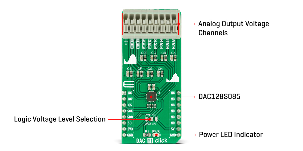
The DAC 11 Click Board™ as its foundation uses the DAC128S085, a general-purpose 12-bit 8-channel digital-to-analogue converter (DAC) from Texas Instruments. The DAC128S085 is fabricated on a CMOS process with an architecture that consists of switches and resistor strings followed by an output buffer. It ensures monotonicity, low power consumption of 4.85mW at 5V, individual channel power-down capability, and has high precision output amplifier that allows rail-to-rail output swing over a wide supply voltage range.
DAC architecture consists of 4096 equal valued resistors with a switch at each junction of two resistors, plus a switch to ground. The code loaded into the DAC register determines which switch is closed, connecting the right node to the amplifier. Because all eight channels of the DAC128S085 can be controlled independently, each consists of a DAC register and a 12-bit DAC. Depending on the mode of operation, data written into a DAC register causes the 12-bit DAC output to be updated, or an additional command is required to update the DAC output. Also, a Power-On reset circuit ensures that the DAC outputs power up to zero volts and remains there until there is a valid write to the device.
The DAC 11 Click Board™ communicates with MCU using the SPI serial interface compatible with standard QSPI, MICROWIRE, and DSP interfaces, with a maximum frequency of 50 MHz. Also, this Click board™ is designed to utilize the entire dynamic range of DAC128S085 by having all power supply pins (and reference voltage pins) connected together, sharing the same supply voltage. In addition, the user is given the option of further use of the RC filter at the output to roll off output noise.
The DAC 11 Click Board™ can operate with both 3.3V and 5V logic voltage levels selected via the VCC SEL jumper. This way, it is allowed for both 3.3V and 5V capable MCUs to use the SPI communication lines properly. However, the Click board™ comes equipped with a library containing easy-to-use functions and an example code that can be used, as a reference, for further development.
| Type | DAC |
| Applications | Can be used for digital gain and offset adjustment applications, programmable voltage and current sources, programmable reference, and many more |
| On-board modules | DAC128S085 - general-purpose 12-bit 8-channel digital-to-analog converter (DAC) from Texas Instruments |
| Key Features | Low power consumption, high precission, ensured monotonicity, rail-to-rail voltage output, simultaneous output updating, individual channel power-down capability, and more |
| Interface | SPI |
| Compatibility | mikroBUS |
| Click board size | L (57.15 x 25.4 mm) |
| Input Voltage | 3.3V or 5V |
This table shows how the pinout on the DAC 11 Click Board™ corresponds to the pinout on the mikroBUS™ socket (the latter shown in the two middle columns).
| Notes | Pin | Pin | Notes | ||||
|---|---|---|---|---|---|---|---|
| NC | 1 | AN | PWM | 16 | NC | ||
| NC | 2 | RST | INT | 15 | NC | ||
| SPI Chip Select | CS | 3 | CS | RX | 14 | NC | |
| SPI Clock | SCK | 4 | SCK | TX | 13 | NC | |
| SPI Data OUT | SDO | 5 | MISO | SCL | 12 | NC | |
| SPI Data IN | SDI | 6 | MOSI | SDA | 11 | NC | |
| Power Supply | 3.3V | 7 | 3.3V | 5V | 10 | 5V | Power Supply |
| Ground | GND | 8 | GND | GND | 9 | GND | Ground |
| Label | Name | Default | Description |
|---|---|---|---|
| LD1 | PWR | - | Power LED Indicator |
| JP1 | VCC SEL | Left | Logic Level Voltage Selection 3V3/5V: Left position 3V3, Right position 5V |
| Description | Min | Typ | Max | Unit |
|---|---|---|---|---|
| Supply Voltage | 3.3 | - | 5 | V |
| Output Voltage Range | 0 | - | 5 | V |
| Resolution | 12 | - | - | bits |
| Operating Temperature Range | -40 | +25 | +125 | °C |
We provide a library for the DAC 11 Click Board™ as well as a demo application (example), developed using MikroElektronika compilers. The demo can run on all the main MikroElektronika development boards.
The package can be downloaded/installed directly from NECTO Studio Package Manager(recommended way), downloaded from our LibStock™ or found on Mikroe GitHub account.
This library contains API for DAC 11 Click driver.
dac11_cfg_setup - Config Object Initialization function.dac11_init - Initialization function.dac11_default_cfg - Click the Default Configuration function.This example demonstrates the use of the DAC 11 Click Board™.
void application_task ( void )
{
    float step = REFERENCE_VOLTAGE / NUMBER_OF_STEPS;
    float output_voltage = step;
    uint8_t cnt = 0;
    while ( cnt < NUMBER_OF_STEPS )
    {
        dac11_set_all_ch_voltage ( &dac11, REFERENCE_VOLTAGE, output_voltage );
        log_printf( &logger, " All channels output voltage set to %.2f Vrn", output_voltage );

        output_voltage += step;
        cnt++;
        Delay_ms( 2000 );
    }
}
The full application code, and ready to use projects can be installed directly from NECTO Studio Package Manager(recommended way), downloaded from our LibStock™ or found on Mikroe GitHub account.
Other mikroE Libraries used in the example:
Depending on the development board you are using, you may need a USB UART click, USB UART 2 click or RS232 click to connect to your PC, for development systems with no UART to USB interface available on the board. The terminal available in all MikroElektronika compilers, or any other terminal application of your choice, can be used to read the message.
The DAC 11 Click Board™ is supported with mikroSDK - MikroElektronika Software Development Kit. To ensure proper operation of mikroSDK compliant Click board™ demo applications, mikroSDK should be downloaded from the LibStock and installed for the compiler you are using.
- manufacturer: Mikroelektronika d.o.o. - warranty: 12 months - mpn: MIKROE-4767 - backorder_label: If no stock shown above, check availability - attachments: [{"download_file":[{"download_file":"DAC 11 Click Board™ Schematic"}],"download_filetype":[{"download_filetype":"pdf"}]},{"download_file":[{"download_file":"Texas Instruments DAC128S085 12-bit DAC Datasheet"}],"download_filetype":[{"download_filetype":"pdf"}]}] - condition: new - custom_product: false - mpn: MIKROE-4767 - google_product_category: Electronics - custom_label_0: Click Board - key_feature_2: Low power consumption, high precission, ensured monotonicity, rail-to-rail voltage output, simultaneous output updating, individual channel power-down capability, and more - key_feature_3: Based on the DAC128S085 - general-purpose 12-bit 8-channel digital-to-analogue converter (DAC) from Texas Instruments - key_feature_4: Can be used for digital gain and offset adjustment applications, programmable voltage and current sources, programmable reference, and many more - key_feature_5: mikroBUS: SPI Interface - device_vendor: Texas Instruments - device_type: DAC128S085CISQ/NOPB - warranty: 12 months - brand: MikroE - manufacturer: Mikroelektronika d.o.o. - target_keyword: DAC 11 Click Board - brands: gid://shopify/Metaobject/56256004319 - breadcrumbs: ["gid://shopify/Collection/447955239135","gid://shopify/Collection/241680580797","gid://shopify/Collection/241545314493"] - customhs_code: 847330 - detailed_description: {"type":"root","children":[{"type":"heading","level":3,"children":[{"type":"text","value":"How Does The DAC 11 Click Board™ Work?"}]},{"type":"paragraph","children":[{"type":"text","value":"The "},{"type":"text","value":"DAC 11 Click Board™","bold":true,"italic":true},{"type":"text","value":" as its foundation uses the DAC128S085, a general-purpose 12-bit 8-channel digital-to-analogue converter (DAC) from Texas Instruments. The DAC128S085 is fabricated on a CMOS process with an architecture that consists of switches and resistor strings followed by an output buffer. It ensures monotonicity, low power consumption of 4.85mW at 5V, individual channel power-down capability, and has high precision output amplifier that allows rail-to-rail output swing over a wide supply voltage range."}]},{"type":"paragraph","children":[{"type":"text","value":""}]},{"type":"paragraph","children":[{"type":"text","value":"DAC architecture consists of 4096 equal valued resistors with a switch at each junction of two resistors, plus a switch to ground. The code loaded into the DAC register determines which switch is closed, connecting the right node to the amplifier. Because all eight channels of the DAC128S085 can be controlled independently, each consists of a DAC register and a 12-bit DAC. Depending on the mode of operation, data written into a DAC register causes the 12-bit DAC output to be updated, or an additional command is required to update the DAC output. Also, a Power-On reset circuit ensures that the DAC outputs power up to zero volts and remains there until there is a valid write to the device."}]},{"type":"paragraph","children":[{"type":"text","value":"The "},{"type":"text","value":"DAC 11 Click Board™","bold":true},{"type":"text","value":" communicates with MCU using the SPI serial interface compatible with standard QSPI, MICROWIRE, and DSP interfaces, with a maximum frequency of 50 MHz. Also, this Click board™ is designed to utilize the entire dynamic range of DAC128S085 by having all power supply pins (and reference voltage pins) connected together, sharing the same supply voltage. In addition, the user is given the option of further use of the RC filter at the output to roll off output noise."}]},{"type":"paragraph","children":[{"type":"text","value":"The "},{"type":"text","value":"DAC 11 Click Board™","bold":true},{"type":"text","value":" can operate with both 3.3V and 5V logic voltage levels selected via the VCC SEL jumper. This way, it is allowed for both 3.3V and 5V capable MCUs to use the SPI communication lines properly. However, the Click board™ comes equipped with a library containing easy-to-use functions and an example code that can be used, as a reference, for further development."}]},{"type":"heading","level":3,"children":[{"type":"text","value":"Specifications"}]},{"type":"paragraph","children":[{"type":"text","value":"Type\nDAC\nApplications\nCan be used for digital gain and offset adjustment applications, programmable voltage and current sources, programmable reference, and many more\nOn-board modules\nDAC128S085 - general-purpose 12-bit 8-channel digital-to-analog converter (DAC) from Texas Instruments\nKey Features\nLow power consumption, high precission, ensured monotonicity, rail-to-rail voltage output, simultaneous output updating, individual channel power-down capability, and more\nInterface\nSPI\nCompatibility\nmikroBUS\nClick board size\nL (57.15 x 25.4 mm)\nInput Voltage\n3.3V or 5V"}]},{"type":"heading","level":3,"children":[{"type":"text","value":"Pinout diagram"}]},{"type":"paragraph","children":[{"type":"text","value":"This table shows how the pinout on the "},{"type":"text","value":"DAC 11 Click Board™","bold":true},{"type":"text","value":" corresponds to the pinout on the mikroBUS™ socket (the latter shown in the two middle columns)."}]},{"type":"paragraph","children":[{"type":"text","value":"Notes\nPin\nPin\nNotes\nNC\n1\nAN\nPWM\n16\nNC\nNC\n2\nRST\nINT\n15\nNC\nSPI Chip Select\nCS\n3\nCS\nRX\n14\nNC\nSPI Clock\nSCK\n4\nSCK\nTX\n13\nNC\nSPI Data OUT\nSDO\n5\nMISO\nSCL\n12\nNC\nSPI Data IN\nSDI\n6\nMOSI\nSDA\n11\nNC\nPower Supply\n3.3V\n7\n3.3V\n5V\n10\n5V\nPower Supply\nGround\nGND\n8\nGND\nGND\n9\nGND\nGround"}]},{"type":"heading","level":3,"children":[{"type":"text","value":"Onboard settings and indicators"}]},{"type":"paragraph","children":[{"type":"text","value":"Label\nName\nDefault\n Description\nLD1\nPWR\n-\nPower LED Indicator\nJP1\nVCC SEL\nLeft\nLogic Level Voltage Selection 3V3/5V: Left position 3V3, Right position 5V"}]},{"type":"heading","level":3,"children":[{"type":"text","value":"DAC 11 Click electrical specifications"}]},{"type":"paragraph","children":[{"type":"text","value":"Description\nMin\nTyp\nMax\nUnit\nSupply Voltage\n3.3\n-\n5\nV\nOutput Voltage Range\n0\n-\n5\nV\nResolution\n12\n-\n-\nbits\nOperating Temperature Range\n-40\n+25\n+125\n°C"}]},{"type":"heading","level":3,"children":[{"type":"text","value":" "}]}]} - summary:The DAC 11 Click Board™ is a compact add-on board that contains a highly accurate digital-to-analogue converter. This board features the DAC128S085, a general-purpose OCTAL 12-bit analogue voltage-output DAC from Texas Instruments. It uses both logic voltage levels from the mikroBUS™ socket with a maximum power consumption of 4.85mW at 5V. The on-chip output amplifiers allow rail-to-rail output swing, supporting the SPI serial interface (compatible with standard QSPI, MICROWIRE, and DSP interfaces), which operates at clock rates up to 40MHz. This Click Board™ represents an excellent choice for digital gain and offset adjustment applications, programmable voltage and current sources, programmable reference, and many more.
The DAC 11 Click Board™ is supported by a mikroSDK compliant library, which includes functions that simplify software development. This Click Board™ comes as a fully tested product, ready to be used on a system equipped with the mikroBUS™ socket.