The I2C to CAN Click Board™ as its foundation uses the LT3960, I2C to CAN-Physical transceiver used to send and receive I2C data up to 400kbps using the CAN-Physical layer for differential signaling over twisted pair connections from Analog Devices. Using two integrated CAN transceivers, the LT3960 creates a differential proxy for each single-ended I2C clock and data signal capable of crossing harsh or noisy environments across two twisted pairs. Each transceiver consists of a transmitter and receiver, capable of quickly converting I2C dominant signal into a differential dominant signal and vice versa. Also, it extends functionality in environments with high common-mode voltages due to electrical noise or local ground potential differences.
The I2C to CAN Click Board™ communicates with MCU using the standard I2C 2-Wire interface to read data and configure settings, supporting Fast Mode operation with a clock frequency up to 400kHz. The LT3960 provides a mode selection feature selectable via jumper labelled as MODE, where the user can choose between Master or Slave mode of operation. The SHD pin routed to the CS pin of the mikroBUS™ socket is used to put the LT3960 in a low-power Shutdown mode, disabling both the LDO and transceivers and allows selection between Master and Slave modes when enabled.
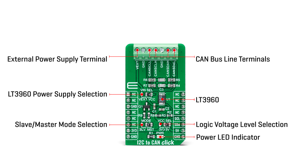
The selection between Master and Slave mode is performed by positioning the SMD jumper labelled as MODE to an appropriate position marked as SLV and MST. When a jumper is on the MST position, Master mode is selected, and the EN/MODE pin of the LT3960 is tied to a high logic state, while floating this pin, more precisely positioning the SMD jumper to an SLV position, allows the user to select Slave mode of operation.
The I2C to CAN Click Board™ can operate with both 3.3V and 5V logic voltage levels selected via the VCC SEL jumper. It allows for both 3.3V and 5V capable MCUs to use the I2C communication lines properly. Additionally, there is a possibility for the LT3960 power supply selection via jumper labelled as VIN SEL to supply the LT3960 from an external power supply terminal in the range from 4 to 60V or with VCC voltage levels from mikroBUS™ power rails. However, the Click board™ comes equipped with a library containing easy-to-use functions and an example code that can be used, as a reference, for further development.
| Type | CAN |
| Applications | Can be used for industrial and automotive networking, remote sensor applications, and more. |
| On-board modules | LT3960 - I2C to CAN-Physical transceiver used to send and receive I2C data up to 400kbps using the CAN-Physical layer for differential signaling over twisted pair connections from Analog Devices |
| Key Features | High speed I2C to CAN-physical transceiver, up to 400kbps I2C communications, up to 60V power supply, low current Shutdown mode, and more. |
| Interface | I2C |
| Compatibility | mikroBUS |
| Click board size | M (42.9 x 25.4 mm) |
| Input Voltage | 3.3V or 5V,External |
This table shows how the pinout of the I2C to CAN Click Board™ corresponds to the pinout on the mikroBUS™ socket (the latter shown in the two middle columns).
| Notes | Pin | Pin | Notes | ||||
|---|---|---|---|---|---|---|---|
| NC | 1 | AN | PWM | 16 | NC | ||
| NC | 2 | RST | INT | 15 | NC | ||
| Shutdown | SHD | 3 | CS | RX | 14 | NC | |
| NC | 4 | SCK | TX | 13 | NC | ||
| NC | 5 | MISO | SCL | 12 | SCL | I2C Clock | |
| NC | 6 | MOSI | SDA | 11 | SDA | I2C Data | |
| Power Supply | 3.3V | 7 | 3.3V | 5V | 10 | 5V | Power Supply |
| Ground | GND | 8 | GND | GND | 9 | GND | Ground |
| Label | Name | Default | Description |
|---|---|---|---|
| LD1 | PWR | - | Power LED Indicator |
| JP1 | VCC SEL | Left | Logic Level Voltage Selection 3V3/5V: Left position 3V3, Right position 5V |
| JP2 | VIN SEL | Right | LT3960 Power Supply Voltage Selection VEXT/VCC: Left position VEXT, Right position VCC |
| JP3 | MODE | Right | Slave/Master Mode Selection SLV/MST: Left position SLV, Right position MST |
| Description | Min | Typ | Max | Unit |
|---|---|---|---|---|
| Supply Voltage VCC | 3.3 | - | 5 | V |
| Supply Voltage VIN | 4 | - | 60 | V |
| Data Rate | - | - | 400 | kbps |
| Operating Temperature Range | -40 | +25 | +125 | °C |
We provide a library for the I2C to CAN Click Board™ as well as a demo application (example), developed using MikroElektronika compilers. The demo can run on all the main MikroElektronika development boards.
The package can be downloaded/installed directly from NECTO Studio The package Manager (recommended), downloaded from our LibStock™ or found on mikroE Github account.
This library contains API for the I2C to CAN Click Board™ driver.
i2ctocan_cfg_setup - Config Object Initialization function.i2ctocan_init - Initialization function.i2ctocan_default_cfg - Click Default Configuration function.This library contains API for the I2C to CAN Click Board™ driver. This demo application shows an example of an I2C to CAN wired to the VAV Press Click for reading differential pressure and temperature measurement.
void application_init ( void ) {
    log_cfg_t log_cfg;            /**< Logger config object. */
    i2ctocan_cfg_t i2ctocan_cfg;  /**< Click config object. */

    // Logger initialization.

    LOG_MAP_USB_UART( log_cfg );
    log_cfg.level = LOG_LEVEL_DEBUG;
    log_cfg.baud = 115200;
    log_init( &logger, &log_cfg );
    log_printf( &logger, "rn" );
    log_info( &logger, " Application Init " );

    // Click initialization.

    i2ctocan_cfg_setup( &i2ctocan_cfg );
    I2CTOCAN_MAP_MIKROBUS( i2ctocan_cfg, MIKROBUS_1 );
    err_t init_flag = i2ctocan_init( &i2ctocan, &i2ctocan_cfg );
    if ( init_flag == I2C_MASTER_ERROR ) {
        log_error( &logger, " Application Init Error. " );
        log_info( &logger, " Please, run program again... " );

        for ( ; ; );
    }

    i2ctocan_default_cfg ( &i2ctocan );
    log_info( &logger, " Application Task " );
    Delay_ms( 100 );

    log_printf( &logger, "--------------------------------rn" );
    log_printf( &logger, "     Set I2C Slave Address      rn" );
    i2ctocan_set_slave_address ( &i2ctocan, I2CTOCAN_VAV_PRESS_DEV_ADDR );
    Delay_ms( 100 );

    log_printf( &logger, "--------------------------------rn" );
    log_printf( &logger, "          Enable Device         rn" );
    log_printf( &logger, "--------------------------------rn" );
    i2ctocan_enable_device( &i2ctocan );
    Delay_ms( 100 );
}
The full application code, and ready to use projects can be installed directly from NECTO Studio The package Manager (recommended), downloaded from our LibStock™ or found on mikroE Github account.
Other mikroE Libraries used in the example:
Depending on the development board you are using, you may need USB UART Click Board™, USB UART 2 Click Board™ or RS232 Click Board™ to connect to your PC, for development systems with no UART to USB interface available on the board. The terminal available in all MikroElektronika compilers, or any other terminal application of your choice, can be used to read the message.
The I2C to CAN Click Board™ is supported with mikroSDK - MikroElektronika Software Development Kit. To ensure proper operation of mikroSDK compliant Click board™ demo applications, mikroSDK should be downloaded from the LibStock and installed for the compiler you are using.
- attachments: [{"download_file":[{"download_file":"I2C to CAN Click Board™ Schematic"}],"download_filetype":[{"download_filetype":"pdf"}]},{"download_file":[{"download_file":"Analog Devices LT3960 CAN Bus Transceiver Datasheet"}],"download_filetype":[{"download_filetype":"pdf"}]}] - device_vendor: Analog Devices Inc. - device_type: LT3960EMSE#PBF - warranty: 12 months - brand: MikroE - manufacturer: Mikroelektronika d.o.o. - target_keyword: I2C to CAN Click Board - brands: gid://shopify/Metaobject/56256004319 - breadcrumbs: ["gid://shopify/Collection/447955239135","gid://shopify/Collection/241680580797","gid://shopify/Collection/241546100925"] - customhs_code: 847330 - detailed_description: {"type":"root","children":[{"type":"heading","level":3,"children":[{"type":"text","value":"How Does The I2C to CAN Click Board™ Work?"}]},{"type":"paragraph","children":[{"type":"text","value":"The "},{"type":"text","value":"I2C to CAN Click Board™","bold":true,"italic":true},{"type":"text","value":" as its foundation uses the LT3960, I2C to CAN-Physical transceiver used to send and receive I2C data up to 400kbps using the CAN-Physical layer for differential signaling over twisted pair connections from Analog Devices. Using two integrated CAN transceivers, the LT3960 creates a differential proxy for each single-ended I2C clock and data signal capable of crossing harsh or noisy environments across two twisted pairs. Each transceiver consists of a transmitter and receiver, capable of quickly converting I2C dominant signal into a differential dominant signal and vice versa. Also, it extends functionality in environments with high common-mode voltages due to electrical noise or local ground potential differences."}]},{"type":"paragraph","children":[{"type":"text","value":""}]},{"type":"paragraph","children":[{"type":"text","value":"The "},{"type":"text","value":"I2C to CAN Click Board™","bold":true},{"type":"text","value":" communicates with MCU using the standard I2C 2-Wire interface to read data and configure settings, supporting Fast Mode operation with a clock frequency up to 400kHz. The LT3960 provides a mode selection feature selectable via jumper labelled as MODE, where the user can choose between Master or Slave mode of operation. The SHD pin routed to the CS pin of the mikroBUS™ socket is used to put the LT3960 in a low-power Shutdown mode, disabling both the LDO and transceivers and allows selection between Master and Slave modes when enabled."}]},{"type":"paragraph","children":[{"type":"text","value":"The selection between Master and Slave mode is performed by positioning the SMD jumper labelled as MODE to an appropriate position marked as SLV and MST. When a jumper is on the MST position, Master mode is selected, and the EN/MODE pin of the LT3960 is tied to a high logic state, while floating this pin, more precisely positioning the SMD jumper to an SLV position, allows the user to select Slave mode of operation."}]},{"type":"paragraph","children":[{"type":"text","value":"The "},{"type":"text","value":"I2C to CAN Click Board™","bold":true},{"type":"text","value":" can operate with both 3.3V and 5V logic voltage levels selected via the VCC SEL jumper. It allows for both 3.3V and 5V capable MCUs to use the I2C communication lines properly. Additionally, there is a possibility for the LT3960 power supply selection via jumper labelled as VIN SEL to supply the LT3960 from an external power supply terminal in the range from 4 to 60V or with VCC voltage levels from mikroBUS™ power rails. However, the Click board™ comes equipped with a library containing easy-to-use functions and an example code that can be used, as a reference, for further development."}]},{"type":"heading","level":3,"children":[{"type":"text","value":"SPECIFICATIONS"}]},{"type":"paragraph","children":[{"type":"text","value":"Type\nCAN\nApplications\nCan be used for industrial and automotive networking, remote sensor applications, and more.\nOn-board modules\nLT3960 - I2C to CAN-Physical transceiver used to send and receive I2C data up to 400kbps using the CAN-Physical layer for differential signaling over twisted pair connections from Analog Devices\nKey Features\nHigh speed I2C to CAN-physical transceiver, up to 400kbps I2C communications, up to 60V power supply, low current Shutdown mode, and more.\nInterface\nI2C\nCompatibility\nmikroBUS\nClick board size\nM (42.9 x 25.4 mm)\nInput Voltage\n3.3V or 5V,External"}]},{"type":"heading","level":3,"children":[{"type":"text","value":"PINOUT DIAGRAM"}]},{"type":"paragraph","children":[{"type":"text","value":"This table shows how the pinout of the "},{"type":"text","value":"I2C to CAN Click Board™","bold":true},{"type":"text","value":" corresponds to the pinout on the mikroBUS™ socket (the latter shown in the two middle columns)."}]},{"type":"paragraph","children":[{"type":"text","value":"Notes\nPin\nPin\nNotes\nNC\n1\nAN\nPWM\n16\nNC\nNC\n2\nRST\nINT\n15\nNC\nShutdown\nSHD\n3\nCS\nRX\n14\nNC\nNC\n4\nSCK\nTX\n13\nNC\nNC\n5\nMISO\nSCL\n12\nSCL\nI2C Clock\nNC\n6\nMOSI\nSDA\n11\nSDA\nI2C Data\nPower Supply\n3.3V\n7\n3.3V\n5V\n10\n5V\nPower Supply\nGround\nGND\n8\nGND\nGND\n9\nGND\nGround"}]},{"type":"heading","level":3,"children":[{"type":"text","value":"ONBOARD SETTINGS AND INDICATORS"}]},{"type":"paragraph","children":[{"type":"text","value":"Label\nName\nDefault\nDescription\nLD1\nPWR\n-\nPower LED Indicator\nJP1\nVCC SEL\nLeft\nLogic Level Voltage Selection 3V3/5V: Left position 3V3, Right position 5V\nJP2\nVIN SEL\nRight\nLT3960 Power Supply Voltage Selection VEXT/VCC: Left position VEXT, Right position VCC\nJP3\nMODE\nRight\nSlave/Master Mode Selection SLV/MST: Left position SLV, Right position MST"}]},{"type":"heading","level":3,"children":[{"type":"text","value":"I2C TO CAN CLICK ELECTRICAL SPECIFICATIONS"}]},{"type":"paragraph","children":[{"type":"text","value":"Description\nMin\nTyp\nMax\nUnit\nSupply Voltage VCC\n3.3\n-\n5\nV\nSupply Voltage VIN\n4\n-\n60\nV\nData Rate\n-\n-\n400\nkbps\nOperating Temperature Range\n-40\n+25\n+125\n°C"}]},{"type":"heading","level":3,"children":[{"type":"text","value":" "}]}]} - summary:The I2C to CAN Click Board™ is a compact add-on board that contains I2C to CAN-physical transceiver, which extends a single-master I2C bus through harsh or noisy environments. This board features the LT3960, a robust high-speed transceiver that extends a single-master I2C bus up to 400kbps using the CAN-physical layer from Analog Devices. One LT3960 from SCL and SDA I2C lines creates equivalent differential buses (CAN) on two twisted pairs, while the second LT3960 recreates the I2C bus locally for any slave I2C devices on the other end of the twisted pairs. A built-in 3.3V LDO powers the I2C and CAN lines from a single input supply from 4V to 60V.
The I2C to CAN Click Board™ is suitable for industrial and automotive networking, remote sensor applications, and more.