
The CAN Bus Click Board™ as its foundation uses the MAX13054, ±80V fault-protected CAN-transceiver ideal for industrial network applications that require overvoltage protection from Maxim Integrated. The MAX13054 provides a link between the CAN protocol controller and the physical wires of the bus lines in a control area network (CAN). These devices can be used for DeviceNet applications, requiring data rates up to 1Mbps. Its input common-mode range is greater than ±12V, exceeding the ISO11898 specification of -2V to +7V, and features ±8kV Contact Discharge protection, making these devices ideal for harsh industrial environments.
Its dominant timeout feature prevents the bus from being blocked by MCU. If the TXD input is held low for greater than 1ms, the transmitter becomes disabled, driving the bus line to a recessive state. In Standby mode, when STB pin routed on the AN and INT pin of the mikroBUS™ socket is set to a high logic state, the transmitter is switched off, and the receiver is switched to a low-current/low-speed state. Activation of Standby mode is possible by setting the onboard SMD jumper labelled as STBY SEL to an appropriate position marked as STB or GND.
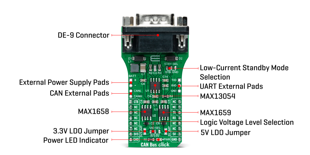
The MAX13054 communicates with MCU using the UART interface with the default baud rate of 115200 bps for the data transfer. In addition to UART communication pins from the mikroBUS™ socket, the user can connect the TX/RX signals directly through the UART External header on the right edge of the board. The CAN Bus Click Board™ comes equipped with the standard DB-9 connector, making interfacing with the CAN bus simple and easy. Besides, the user can connect the CAN signals directly through the CAN External header, also on the left edge of the board.
The external power supply in a range from 2.7V to 16.5V, next to the D-9 connector, can also be brought to the header labelled BATT on the board's left side. Through SMD jumpers labelled as 3V3 JMP and 5V JMP, the MAX1658/59 from Maxim Integrated LDOs output voltages can power up the mikroBUS™ 3.3V and 5V power rails. This feature makes the MAX13054 ideal for many different applications, including those in the automotive market. However, it should be noted that Mikroe does not advise powering up their systems this way. That is why these jumpers are left unpopulated by default.
The CAN Bus Click Board™ can operate with both 3.3V and 5V logic voltage levels selected via the VIO SEL jumper. It allows for both 3.3V and 5V capable MCUs to use the UART communication lines properly. However, the Click board™ comes equipped with a library containing easy-to-use functions and an example code that can be used, as a reference, for further development.
| Type | CAN |
| Applications | Can be used for harsh industrial environments and industrial network applications where overvoltage protection is required |
| On-board modules | MAX13054 - ±80V fault-protected CAN-transceiver ideal for industrial network applications that require overvoltage protection from Maxim Integrated |
| Key Features | Fully compatible with the ISO11898 standard, ±80V fault protection, high-speed operation of up to 1Mbps, low-current Standby mode, transmit data dominant timeout, and more. |
| Interface | UART |
| Compatibility | mikroBUS |
| Click board size | L (57.15 x 25.4 mm) |
| Input Voltage | 3.3V or 5V, External |
This table shows how the pinout for the CAN Bus Click Board™ corresponds to the pinout on the mikroBUS™ socket (the latter shown in the two middle columns).
| Notes | Pin | |
Pin | Notes | |||
|---|---|---|---|---|---|---|---|
| Standby Mode | STB | 1 | AN | PWM | 16 | NC | |
| NC | 2 | RST | INT | 15 | NC | ||
| NC | 3 | CS | RX | 14 | TX | UART TX | |
| NC | 4 | SCK | TX | 13 | RX | UART RX | |
| NC | 5 | MISO | SCL | 12 | NC | ||
| NC | 6 | MOSI | SDA | 11 | NC | ||
| Power Supply | 3.3V | 7 | 3.3V | 5V | 10 | 5V | Power Supply |
| Ground | GND | 8 | GND | GND | 9 | GND | Ground |
| Label | Name | Default | Description |
|---|---|---|---|
| LD1 | PWR | - | Power LED Indicator |
| JP1 | VIO SEL | Left | Logic Level Voltage Selection 3V3/5V: Left position 3V3, Right position 5V |
| JP2 | STBY SEL | Left | Low-Current Standby Mode Selection STB/GND: Left position STB, Right position GND |
| JMPR1 | 3V3 JMP | Unpopulated | 3V3 LDO Jumper |
| JMPR2 | 5V JMP | Unpopulated | 5V LDO Jumper |
| J1 | BATT | Unpopulated | External Power Supply Header |
| J2 | UART | Unpopulated | External UART TX/RX Lines Header |
| J3 | CAN | Unpopulated | External CANH/CANL Lines Header |
| Description | Min | Typ | Max | Unit |
|---|---|---|---|---|
| Supply Voltage VIO | 3.3 | - | 5 | V |
| External Supply Voltage BATT | 2.7 | - | 16.5 | V |
| Receiver inputs voltage range | - | - | 1 | Mbps |
| Receiver inputs voltage range | -40 | +25 | +125 | °C |
We provide a library for the CAN Bus Click Board™ as well as a demo application (example), developed using MikroElektronika compilers. The demo can run on all the main MikroElektronika development boards.
The package can be downloaded/installed directly from NECTO Studio Package Manager (recommended), downloaded from our LibStock™ or found on mikroE Github account.
This library contains an API for the CAN Bus Click Board™ driver.
canbus_cfg_setup - Config Object Initialization function.canbus_init - Initialization function.canbus_default_cfg - Click the Default Configuration function.This library contains API for CAN Bus click board™. This example transmits/receives and processes data from the CAN Bus Click Board™. The library initializes and defines the UART bus drivers to transmit or receive data.
The demo application is composed of two sections :
void application_task ( void ) {
 #ifdef TRANSMIT
     canbus_send_data( &canbus, demo_message );
     log_printf( &logger, "t%s", demo_message );
     Delay_ms( 2000 );
     log_printf( &logger, "------------------rn" );
 #endif

 #ifdef RECIEVER
 canbus_process( );
 if ( app_buf_len > 0 ) {
     log_printf( &logger, "%s", app_buf );
     canbus_clear_app_buf( );
 }
 #endif
}
The full application code, and ready to use projects can be installed directly from NECTO Studio Package Manager (recommended), downloaded from our LibStock™ or found on mikroE Github account.
Other mikroE Libraries used in the example:
Depending on the development board you are using, you may need a USB UART click, USB UART 2 click or RS232 click to connect to your PC, for development systems with no UART to USB interface available on the board. The terminal available in all MikroElektronika compilers, or any other terminal application of your choice, can be used to read the message.
The CAN Bus Click Board™ is supported with mikroSDK - MikroElektronika Software Development Kit. To ensure proper operation of mikroSDK compliant Click board™ demo applications, mikroSDK should be downloaded from the LibStock and installed for the compiler you are using.
- attachments: [{"download_file":[{"download_file":"CAN Bus Click Board™ Schematic"}],"download_filetype":[{"download_filetype":"pdf"}]},{"download_file":[{"download_file":"Maxim MAX1658/59 Low Dropout Regulator Datasheet"}],"download_filetype":[{"download_filetype":"pdf"}]},{"download_file":[{"download_file":"Maxim MAX13054 CAN Bus Transceiver Datasheet"}],"download_filetype":[{"download_filetype":"pdf"}]}] - condition: new - custom_product: false - mpn: MIKROE-4640 - google_product_category: Electronics - custom_label_0: Click Board - key_feature_2: Fully compatible with the ISO11898 standard, ±80V fault protection, high-speed operation of up to 1Mbps, low-current Standby mode, transmit data dominant timeout, and more. - key_feature_3: Based on the MAX13054 - ±80V fault-protected CAN-transceiver ideal for industrial network applications that require overvoltage protection from Maxim Integrated - key_feature_4: Can be used for harsh industrial environments and industrial network applications where overvoltage protection is required - key_feature_5: mikroBUS: UART Interface - device_vendor: Maxim Integrated - device_type: MAX13054ASA+, MAX1658ESA+, MAX1659ESA+ - warranty: 12 months - brand: MikroE - manufacturer: Mikroelektronika d.o.o. - target_keyword: CAN Bus Click Board - brands: gid://shopify/Metaobject/56256004319 - breadcrumbs: ["gid://shopify/Collection/447955239135","gid://shopify/Collection/241680580797","gid://shopify/Collection/241546100925"] - customhs_code: 847330 - detailed_description: {"type":"root","children":[{"type":"heading","level":3,"children":[{"type":"text","value":"How Does The CAN Bus Click Board™ Work?"}]},{"type":"paragraph","children":[{"type":"text","value":"The"},{"type":"text","value":" CAN Bus Click Board™","bold":true},{"type":"text","value":" as its foundation uses the MAX13054, ±80V fault-protected CAN-transceiver ideal for industrial network applications that require overvoltage protection from Maxim Integrated. The MAX13054 provides a link between the CAN protocol controller and the physical wires of the bus lines in a control area network (CAN). These devices can be used for DeviceNet applications, requiring data rates up to 1Mbps. Its input common-mode range is greater than ±12V, exceeding the ISO11898 specification of -2V to +7V, and features ±8kV Contact Discharge protection, making these devices ideal for harsh industrial environments."}]},{"type":"paragraph","children":[{"type":"text","value":""},{"type":"text","value":""},{"type":"text","value":""}]},{"type":"paragraph","children":[{"type":"text","value":"Its dominant timeout feature prevents the bus from being blocked by MCU. If the TXD input is held low for greater than 1ms, the transmitter becomes disabled, driving the bus line to a recessive state. In Standby mode, when STB pin routed on the AN and INT pin of the mikroBUS™ socket is set to a high logic state, the transmitter is switched off, and the receiver is switched to a low-current/low-speed state. Activation of Standby mode is possible by setting the onboard SMD jumper labelled as STBY SEL to an appropriate position marked as STB or GND."}]},{"type":"paragraph","children":[{"type":"text","value":"The MAX13054 communicates with MCU using the UART interface with the default baud rate of 115200 bps for the data transfer. In addition to UART communication pins from the mikroBUS™ socket, the user can connect the TX/RX signals directly through the UART External header on the right edge of the board. The "},{"type":"text","value":"CAN Bus Click Board™","bold":true},{"type":"text","value":" comes equipped with the standard DB-9 connector, making interfacing with the CAN bus simple and easy. Besides, the user can connect the CAN signals directly through the CAN External header, also on the left edge of the board."}]},{"type":"paragraph","children":[{"type":"text","value":"The external power supply in a range from 2.7V to 16.5V, next to the D-9 connector, can also be brought to the header labelled BATT on the board's left side. Through SMD jumpers labelled as 3V3 JMP and 5V JMP, the MAX1658/59 from Maxim Integrated LDOs output voltages can power up the mikroBUS™ 3.3V and 5V power rails. This feature makes the MAX13054 ideal for many different applications, including those in the automotive market. However, it should be noted that Mikroe does not advise powering up their systems this way. That is why these jumpers are left unpopulated by default."}]},{"type":"paragraph","children":[{"type":"text","value":"The "},{"type":"text","value":"CAN Bus Click Board™","bold":true},{"type":"text","value":" can operate with both 3.3V and 5V logic voltage levels selected via the VIO SEL jumper. It allows for both 3.3V and 5V capable MCUs to use the UART communication lines properly. However, the Click board™ comes equipped with a library containing easy-to-use functions and an example code that can be used, as a reference, for further development."}]},{"type":"heading","level":3,"children":[{"type":"text","value":"SPECIFICATIONS"}]},{"type":"paragraph","children":[{"type":"text","value":"Type\nCAN\nApplications\nCan be used for harsh industrial environments and industrial network applications where overvoltage protection is required\nOn-board modules\nMAX13054 - ±80V fault-protected CAN-transceiver ideal for industrial network applications that require overvoltage protection from Maxim Integrated\nKey Features\nFully compatible with the ISO11898 standard, ±80V fault protection, high-speed operation of up to 1Mbps, low-current Standby mode, transmit data dominant timeout, and more.\nInterface\nUART\nCompatibility\nmikroBUS\nClick board size\nL (57.15 x 25.4 mm)\nInput Voltage\n3.3V or 5V, External"}]},{"type":"heading","level":3,"children":[{"type":"text","value":"PINOUT DIAGRAM"}]},{"type":"paragraph","children":[{"type":"text","value":"This table shows how the pinout for the "},{"type":"text","value":"CAN Bus Click Board™","bold":true},{"type":"text","value":" corresponds to the pinout on the mikroBUS™ socket (the latter shown in the two middle columns)."}]},{"type":"paragraph","children":[{"type":"text","value":"Notes\nPin\n\nPin\nNotes\nStandby Mode\nSTB\n1\nAN\nPWM\n16\nNC\nNC\n2\nRST\nINT\n15\nNC\nNC\n3\nCS\nRX\n14\nTX\nUART TX\nNC\n4\nSCK\nTX\n13\nRX\nUART RX\nNC\n5\nMISO\nSCL\n12\nNC\nNC\n6\nMOSI\nSDA\n11\nNC\nPower Supply\n3.3V\n7\n3.3V\n5V\n10\n5V\nPower Supply\nGround\nGND\n8\nGND\nGND\n9\nGND\nGround"}]},{"type":"heading","level":3,"children":[{"type":"text","value":"ONBOARD SETTINGS AND INDICATORS"}]},{"type":"paragraph","children":[{"type":"text","value":"Label\nName\nDefault\nDescription\nLD1\nPWR\n-\nPower LED Indicator\nJP1\nVIO SEL\nLeft\nLogic Level Voltage Selection 3V3/5V: Left position 3V3, Right position 5V\nJP2\nSTBY SEL\nLeft\nLow-Current Standby Mode Selection STB/GND: Left position STB, Right position GND\nJMPR1\n3V3 JMP\nUnpopulated\n3V3 LDO Jumper\nJMPR2\n5V JMP\nUnpopulated\n5V LDO Jumper\nJ1\nBATT\nUnpopulated\nExternal Power Supply Header\nJ2\nUART\nUnpopulated\nExternal UART TX/RX Lines Header\nJ3\nCAN\nUnpopulated\nExternal CANH/CANL Lines Header"}]},{"type":"heading","level":3,"children":[{"type":"text","value":"CAN BUS CLICK ELECTRICAL SPECIFICATIONS"}]},{"type":"paragraph","children":[{"type":"text","value":"Description\nMin\nTyp\nMax\nUnit\nSupply Voltage VIO\n3.3\n-\n5\nV\nExternal Supply Voltage BATT\n2.7\n-\n16.5\nV\nReceiver inputs voltage range\n-\n-\n1\nMbps\nReceiver inputs voltage range\n-40\n+25\n+125\n°C"}]},{"type":"heading","level":3,"children":[{"type":"text","value":" "}]}]} - summary:The CAN Bus Click Board™ is a compact add-on board that provides a link between the CAN protocol controller and the physical wires of the bus lines in a control area network (CAN). This board features the MAX13054, an industry-standard, high-speed CAN transceiver with extended ±80V fault protection from Maxim Integrated. The CAN transceiver has an input common-mode range greater than ±12V with data rates up to 1Mbps, exceeding the ISO11898 specification of -2V to +7V, and feature ±8kV ESD protection. It also comes with a Standby feature that shuts off the transmitter and switches the receiver to a low-current/low-speed state.
The CAN Bus Click Board™ is suitable for harsh industrial environments and industrial network applications where overvoltage protection is required.