# Title: LR 4 Click Board™
## Description: How Does The LR 4 Click Board™Work? The LR 4 Click Board™ as its foundation uses the 32001353, a low-power long-range RF technology-based transceiver module from Mipot. It offers a long-range spread spectrum communication with high interference immunity. The network is implemented as a star topology, where endpoints work in duty cycle mode, significantly reducing the overall power consumption. The LR 4 Click Board™ features an embedded LoRaWAN Class A and Class C compliant stack offering an easy and reliable solution for developing low-power, highly integrated IoT networks, security systems, alarm networks, and similar applications that require simple and reliable networking solutions. To join a LoRaWAN network, the 32001353 requires a LoRaWAN concentrator/gateway. The endpoint device has to use a unique endpoint address, an application session key, and a network session key. The first method is called over-the-air activation (OTAA), where these keys are issued after a specific join procedure. The second method is to assign these keys manually, using UART commands. This method is called activation by personalization (ABP) and can be prone to some security issues. In any case, before an end-device can communicate on the LoRaWAN network, it must be activated. The LR 4 Click Board™ communicates with MCU using the UART interface with commonly used UART RX and TX pins at data rates up to 115200bps for the data transfer. In addition to these features, the 32001353 also uses several GPIO pins connected to the mikroBUS™ socket. The WK pin routed on the CS pin of the mikroBUS™ represents the Wake-up function used for waking up the device, while the RST pin on the mikroBUS™ socket can perform Hardware Reset function by putting this pin in a logic low state. This Click board™ also has an indicator routed on the INT pin of the mikroBUS ™ socket, which will provide the user with feedback after a successfully received package and verified checksum. The LR 4 Click Board™ features the SMA antenna connector with an impedance of 50Ω, so it can be equipped with the appropriate 868MHz compliant antenna that MikroE has in its offer. The LR 4 Click Board™can operate with both 3.3V and 5V logic voltage levels selected via the VCC SEL jumper. A proper logic voltage level conversion is performed by the TXB0106 voltage level shifter, while the LDO ensures that recommended values power the module. This allows for both 3.3V and 5V capable MCUs to use the UART communication lines properly. However, the Click board™ comes equipped with a library containing easy-to-use functions and an example code that can be used, as a reference, for further development. SPECIFICATIONS Type LoRa Applications The LR 4 Click Board™ can be used for developing highly integrated long-range IoT networks, security systems, alarm networks, and similar applications that require simple and reliable networking solutions. On-board modules 32001353 - low-power long-range RF technology-based transceiver module from Mipot Radio Region Europe Key Features Low power consumption, RF technology based wireless networking, LoraWAN protocol, easy to use UART interface, and more. Interface UART Compatibility mikroBUS Click board size L (57.15 x 25.4 mm) Input Voltage 3.3V or 5V PINOUT DIAGRAM This table shows how the pinout of the LR 4 Click Board™ corresponds to the pinout on the mikroBUS™ socket (the latter shown in the two middle columns). Notes Pin Pin Notes NC 1 AN PWM 16 NC Reset RST 2 RST INT 15 INT Data TX Indication Wake-Up WKP 3 CS RX 14 TX UART TX NC 4 SCK TX 13 RX UART RX NC 5 MISO SCL 12 NC NC 6 MOSI SDA 11 NC Power Supply 3.3V 7 3.3V 5V 10 5V Power Supply Ground GND 8 GND GND 9 GND Ground ONBOARD SETTINGS AND INDICATORS Label Name Default Description LD1 PWR - Power LED Indicator JP1 VCC SEL Left Logic Level Voltage Selection 3V3/5V: Left position 3V3, Right position 5V LR 4 CLICK ELECTRICAL SPECIFICATIONS Description Min Typ Max Unit Supply Voltage 3.3 - 5 V Operating Frequency Range 863 868 870 MHz Operating Temperature Range -40 +25 +85 °C
## Product type: Click Board
## Vendor: Mikroelektronika d.o.o.
## Tags: Click Board, LoRa, MikroE, Mipot, Wireless
## Price range: 37.8 - 37.8 GBP
## Link: https://thedebugstore.com/products/mikroe-4617-lr-4-click-board-uk
## Compare-at price range: 54.0 - 54.0 GBP
## Options
- Title: Default Title
## Collections
- [New Products](https://thedebugstore.com/a/llms/collections/new-products-debug-store)
- [Mikroelektronika d.o.o. (MikroE)](https://thedebugstore.com/a/llms/collections/mikroelektronika-catalogue-uk)
- [Mipot IoT Device Support: Debug Store's Development Boards and Tools](https://thedebugstore.com/a/llms/collections/devices-mipot)
- [Wireless Interface Click Boards™](https://thedebugstore.com/a/llms/collections/wireless-interface-click-boards-catalogue)
- [MikroE Click Boards™](https://thedebugstore.com/a/llms/collections/mikroe-click-boards-catalogue-uk)
- [LoRa Click Boards™](https://thedebugstore.com/a/llms/collections/lora-click-boards-catalogue)
- [Click Boards™ Summer Sale](https://thedebugstore.com/a/llms/collections/inventory-sale)
- [MikroE Sale](https://thedebugstore.com/a/llms/collections/mikroe-sale)
- [MIKROE Stock](https://thedebugstore.com/a/llms/collections/mikroe-products-in-stock-sale)
## Variants
- Default Title, SKU: MIKROE-4617, Available: yes, Inventory: 1
## Metafields
- title_tag: MikroE LR 4 Click Board™ (MIKROE-4617)
- manufacturer: Mikroelektronika d.o.o.
- warranty: 12 months
- backorder_label: If no stock shown above, check availability
- mpn: MIKROE-4617
- description_tag: The LR 4 Click Board™ is a compact add-on board that contains a long-range transceiver. This board features the 32001353, RF technology-based SRD transceiver, which operates at a frequency of 868MHz from Mipot. Available from Debug Store UK.
- full_description: How Does The LR 4 Click Board™Work?
The LR 4 Click Board™ as its foundation uses the 32001353, a low-power long-range RF technology-based transceiver module from Mipot. It offers a long-range spread spectrum communication with high interference immunity. The network is implemented as a star topology, where endpoints work in duty cycle mode, significantly reducing the overall power consumption. The LR 4 Click Board™ features an embedded LoRaWAN Class A and Class C compliant stack offering an easy and reliable solution for developing low-power, highly integrated IoT networks, security systems, alarm networks, and similar applications that require simple and reliable networking solutions.
To join a LoRaWAN network, the 32001353 requires a LoRaWAN concentrator/gateway. The endpoint device has to use a unique endpoint address, an application session key, and a network session key. The first method is called over-the-air activation (OTAA), where these keys are issued after a specific join procedure. The second method is to assign these keys manually, using UART commands. This method is called activation by personalization (ABP) and can be prone to some security issues. In any case, before an end-device can communicate on the LoRaWAN network, it must be activated.
The LR 4 Click Board™ communicates with MCU using the UART interface with commonly used UART RX and TX pins at data rates up to 115200bps for the data transfer. In addition to these features, the 32001353 also uses several GPIO pins connected to the mikroBUS™ socket. The WK pin routed on the CS pin of the mikroBUS™ represents the Wake-up function used for waking up the device, while the RST pin on the mikroBUS™ socket can perform Hardware Reset function by putting this pin in a logic low state. This Click board™ also has an indicator routed on the INT pin of the mikroBUS ™ socket, which will provide the user with feedback after a successfully received package and verified checksum.
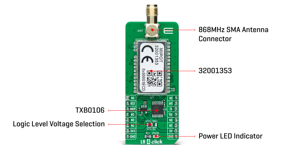
The LR 4 Click Board™ features the SMA antenna connector with an impedance of 50Ω, so it can be equipped with the appropriate 868MHz compliant antenna that MikroE has in its offer.
The LR 4 Click Board™can operate with both 3.3V and 5V logic voltage levels selected via the VCC SEL jumper. A proper logic voltage level conversion is performed by the TXB0106 voltage level shifter, while the LDO ensures that recommended values power the module. This allows for both 3.3V and 5V capable MCUs to use the UART communication lines properly. However, the Click board™ comes equipped with a library containing easy-to-use functions and an example code that can be used, as a reference, for further development.
SPECIFICATIONS
| Type |
LoRa |
| Applications |
The LR 4 Click Board™ can be used for developing highly integrated long-range IoT networks, security systems, alarm networks, and similar applications that require simple and reliable networking solutions. |
| On-board modules |
32001353 - low-power long-range RF technology-based transceiver module from Mipot |
| Radio Region |
Europe |
| Key Features |
Low power consumption, RF technology based wireless networking, LoraWAN protocol, easy to use UART interface, and more. |
| Interface |
UART |
| Compatibility |
mikroBUS |
| Click board size |
L (57.15 x 25.4 mm) |
| Input Voltage |
3.3V or 5V |
PINOUT DIAGRAM
This table shows how the pinout of the LR 4 Click Board™ corresponds to the pinout on the mikroBUS™ socket (the latter shown in the two middle columns).
| Notes |
Pin |
 |
Pin |
Notes |
| NC |
1 |
AN |
PWM |
16 |
NC |
| Reset |
RST |
2 |
RST |
INT |
15 |
INT |
Data TX Indication |
| Wake-Up |
WKP |
3 |
CS |
RX |
14 |
TX |
UART TX |
| NC |
4 |
SCK |
TX |
13 |
RX |
UART RX |
| NC |
5 |
MISO |
SCL |
12 |
NC |
| NC |
6 |
MOSI |
SDA |
11 |
NC |
| Power Supply |
3.3V |
7 |
3.3V |
5V |
10 |
5V |
Power Supply |
| Ground |
GND |
8 |
GND |
GND |
9 |
GND |
Ground |
ONBOARD SETTINGS AND INDICATORS
| Label |
Name |
Default |
Description |
| LD1 |
PWR |
- |
Power LED Indicator |
| JP1 |
VCC SEL |
Left |
Logic Level Voltage Selection 3V3/5V: Left position 3V3, Right position 5V |
LR 4 CLICK ELECTRICAL SPECIFICATIONS
| Description |
Min |
Typ |
Max |
Unit |
| Supply Voltage |
3.3 |
- |
5 |
V |
| Operating Frequency Range |
863 |
868 |
870 |
MHz |
| Operating Temperature Range |
-40 |
+25 |
+85 |
°C |
- google_product_category: 386
- condition: new
- custom_product: false
- mpn: MIKROE-4617
- google_product_category: Electronics
- custom_label_0: Click Board
- examples:
We provide a library for the LR 4 Click Board™ as well as a demo application (example), developed using MikroElektronika compilers. The demo can run on all the main MikroElektronika development boards.
The package can be downloaded/installed directly form compilers IDE(recommended way), or downloaded from our LibStock, or found on mikroE Github account.
Library Description
This library contains API for LR 4 Click driver.
Key Functions
void lr4_cfg_setup ( lr4_cfg_t *cfg ); - Config Object Initialization function.LR4_RETVAL lr4_init ( lr4_t *ctx, lr4_cfg_t *cfg ); - Initialization function.
Example Description
This example reads and processes data from the LR 4 Click Board™.
The demo application is composed of two sections :
void application_task ( void )
{
    log_printf( &logger, "Get Activation Status!rn" );
    uint8_t status = lr4_get_status( &lr4, LR4_GET_ACTIVATION_MODE );
    log_printf( &logger, "Status: " );
    switch ( status )
    {
        case LR4_STATUS_NOT_ACTIVATED :
        {
            log_printf( &logger, "Not activated.rn" );
            break;
        }
        case LR4_STATUS_JOINING :
        {
            log_printf( &logger, "Joining...rn" );
            break;
        }
        case LR4_STATUS_JOINED :
        {
            log_printf( &logger, "Joined.rn" );
            break;
        }
        case LR4_STATUS_MAC_ERROR :
        {
            log_printf( &logger, "MAC ERROR.rn" );
            break;
        }
        default :
        {
            break;
        }
    }
    log_printf( &logger, "------------------------rn" );
    Delay_ms( 1000 );
    log_printf( &logger, "Get Session Status!rn" );
    status = lr4_get_status( &lr4, LR4_GET_SESSION_STATUS_MODE );
    log_printf( &logger, "Status: " );
    switch ( status )
    {
        case LR4_STATUS_IDLE :
        {
            log_printf( &logger, "Idle.rn" );
            break;
        }
        case LR4_STATUS_BUSY :
        {
            log_printf( &logger, "Busy (LR session running).rn" );
            break;
        }
        case LR4_STATUS_DEV_NOT_ACTIVATED :
        {
            log_printf( &logger, "Device not activated.rn" );
            break;
        }
        case LR4_STATUS_DELAYED :
        {
            log_printf( &logger, "Delayed (LR session paused due to Duty-cycle).rn" );
            break;
        }
        default :
        {
            break;
        }
    }
    log_printf( &logger, "------------------------rn" );
    Delay_ms( 1000 );
}
The full application code, and ready to use projects can be installed directly form compilers IDE(recommended) or found on LibStock page or mikroE GitHub account.
Other mikroE Libraries used in the example:
- MikroSDK.Board
- MikroSDK.Log
- Click.LR4
Additional Notes and Information
Depending on the development board you are using, you may need a USB UART click, USB UART 2 click or RS232 click to connect to your PC, for development systems with no UART to USB interface available on the board. The terminal available in all MikroElektronika compilers, or any other terminal application of your choice, can be used to read the message.
MIKROSDK
The LR 4 Click Board™ is supported with mikroSDK - MikroElektronika Software Development Kit. To ensure proper operation of mikroSDK compliant Click board™ demo applications, mikroSDK should be downloaded from the LibStock and installed for the compiler you are using.
- attachments: [{"download_file":[{"download_file":"LR 4 Click Board™ Schematic"}],"download_filetype":[{"download_filetype":"pdf"}]},{"download_file":[{"download_file":"Mipot 32001353 SRD Transceiver Datasheet"}],"download_filetype":[{"download_filetype":"pdf"}]}]
- device_vendor: Mipot, Texas Instruments
- device_type: 32001353, TXB0106PWR
- warranty: 12 months
- brand: MikroE
- manufacturer: Mikroelektronika d.o.o.
- badge: No reviews
- widget:
- target_keyword: LR 4 Click Board
- brands: gid://shopify/Metaobject/56256004319
- breadcrumbs: ["gid://shopify/Collection/447955239135","gid://shopify/Collection/241680580797","gid://shopify/Collection/241546166461"]
- customhs_code: 847330
- detailed_description: {"type":"root","children":[{"type":"heading","level":3,"children":[{"type":"text","value":"How Does The LR 4 Click Board™Work?"}]},{"type":"paragraph","children":[{"type":"text","value":"The "},{"type":"text","value":"LR 4 Click Board™","bold":true,"italic":true},{"type":"text","value":" as its foundation uses the 32001353, a low-power long-range RF technology-based transceiver module from Mipot. It offers a long-range spread spectrum communication with high interference immunity. The network is implemented as a star topology, where endpoints work in duty cycle mode, significantly reducing the overall power consumption. The "},{"type":"text","value":"LR 4 Click Board™","bold":true},{"type":"text","value":" features an embedded LoRaWAN Class A and Class C compliant stack offering an easy and reliable solution for developing low-power, highly integrated IoT networks, security systems, alarm networks, and similar applications that require simple and reliable networking solutions."}]},{"type":"paragraph","children":[{"type":"text","value":""}]},{"type":"paragraph","children":[{"type":"text","value":"To join a LoRaWAN network, the 32001353 requires a LoRaWAN concentrator/gateway. The endpoint device has to use a unique endpoint address, an application session key, and a network session key. The first method is called over-the-air activation (OTAA), where these keys are issued after a specific join procedure. The second method is to assign these keys manually, using UART commands. This method is called activation by personalization (ABP) and can be prone to some security issues. In any case, before an end-device can communicate on the LoRaWAN network, it must be activated."}]},{"type":"paragraph","children":[{"type":"text","value":"The "},{"type":"text","value":"LR 4 Click Board™","bold":true},{"type":"text","value":" communicates with MCU using the UART interface with commonly used UART RX and TX pins at data rates up to 115200bps for the data transfer. In addition to these features, the 32001353 also uses several GPIO pins connected to the mikroBUS™ socket. The WK pin routed on the CS pin of the mikroBUS™ represents the Wake-up function used for waking up the device, while the RST pin on the mikroBUS™ socket can perform Hardware Reset function by putting this pin in a logic low state. This Click board™ also has an indicator routed on the INT pin of the mikroBUS ™ socket, which will provide the user with feedback after a successfully received package and verified checksum."}]},{"type":"paragraph","children":[{"type":"text","value":"The "},{"type":"text","value":"LR 4 Click Board™","bold":true},{"type":"text","value":" features the SMA antenna connector with an impedance of 50Ω, so it can be equipped with the appropriate 868MHz compliant antenna that MikroE has in its offer."}]},{"type":"paragraph","children":[{"type":"text","value":"The "},{"type":"text","value":"LR 4 Click Board™","bold":true},{"type":"text","value":"can operate with both 3.3V and 5V logic voltage levels selected via the VCC SEL jumper. A proper logic voltage level conversion is performed by the TXB0106 voltage level shifter, while the LDO ensures that recommended values power the module. This allows for both 3.3V and 5V capable MCUs to use the UART communication lines properly. However, the Click board™ comes equipped with a library containing easy-to-use functions and an example code that can be used, as a reference, for further development."}]},{"type":"heading","level":3,"children":[{"type":"text","value":"SPECIFICATIONS"}]},{"type":"paragraph","children":[{"type":"text","value":"Type\nLoRa\nApplications\nThe LR 4 Click Board™ can be used for developing highly integrated long-range IoT networks, security systems, alarm networks, and similar applications that require simple and reliable networking solutions.\nOn-board modules\n32001353 - low-power long-range RF technology-based transceiver module from Mipot\nRadio Region\nEurope\nKey Features\nLow power consumption, RF technology based wireless networking, LoraWAN protocol, easy to use UART interface, and more.\nInterface\nUART\nCompatibility\nmikroBUS\nClick board size\nL (57.15 x 25.4 mm)\nInput Voltage\n3.3V or 5V"}]},{"type":"heading","level":3,"children":[{"type":"text","value":"PINOUT DIAGRAM"}]},{"type":"paragraph","children":[{"type":"text","value":"This table shows how the pinout of the "},{"type":"text","value":"LR 4 Click Board™","bold":true},{"type":"text","value":" corresponds to the pinout on the mikroBUS™ socket (the latter shown in the two middle columns)."}]},{"type":"paragraph","children":[{"type":"text","value":"Notes\nPin\nPin\nNotes\nNC\n1\nAN\nPWM\n16\nNC\nReset\nRST\n2\nRST\nINT\n15\nINT\nData TX Indication\nWake-Up\nWKP\n3\nCS\nRX\n14\nTX\nUART TX\nNC\n4\nSCK\nTX\n13\nRX\nUART RX\nNC\n5\nMISO\nSCL\n12\nNC\nNC\n6\nMOSI\nSDA\n11\nNC\nPower Supply\n3.3V\n7\n3.3V\n5V\n10\n5V\nPower Supply\nGround\nGND\n8\nGND\nGND\n9\nGND\nGround"}]},{"type":"heading","level":3,"children":[{"type":"text","value":"ONBOARD SETTINGS AND INDICATORS"}]},{"type":"paragraph","children":[{"type":"text","value":"Label\nName\nDefault\nDescription\nLD1\nPWR\n-\nPower LED Indicator\nJP1\nVCC SEL\nLeft\nLogic Level Voltage Selection 3V3/5V: Left position 3V3, Right position 5V"}]},{"type":"heading","level":3,"children":[{"type":"text","value":"LR 4 CLICK ELECTRICAL SPECIFICATIONS"}]},{"type":"paragraph","children":[{"type":"text","value":"Description\nMin\nTyp\nMax\nUnit\nSupply Voltage\n3.3\n-\n5\nV\nOperating Frequency Range\n863\n868\n870\nMHz\nOperating Temperature Range\n-40\n+25\n+85\n°C"}]},{"type":"heading","level":3,"children":[{"type":"text","value":" "}]}]}
- summary: The LR 4 Click Board™ is a compact add-on board that contains a long-range transceiver. This board features the 32001353, RF technology-based SRD transceiver, which operates at a frequency of 868MHz from Mipot. Thanks to the spread spectrum modulation feature, as well as the low power consumption, it is capable of achieving long-range communication, immune to interferences. It features a complete long-range stack onboard; it implements physical, network, and MAC layers, allowing for easy operation via the UART interface. The transceiver is also RED 2014/53/EU certified, allowing for easy integration into the final application. This Click Board™ offers an easy and reliable solution for developing highly integrated long-range IoT networks, security systems, alarm networks, and similar applications that require simple and reliable networking solutions.
The LR 4 Click Board™ is supported by a mikroSDK compliant library, which includes functions that simplify software development. This Click Board™ comes as a fully tested product, ready to be used on a system equipped with the mikroBUS™ socket.