The DC Motor 17 Click Board™ is based on the TC78H660FTG, a dual H Bridge driver for one or two DC brushed motors that incorporate a DMOS output transistor with low on-resistance from Toshiba Semiconductor. This driver is a PWM controlled constant-current drive with supply voltages from 2.5 to 16V and 2A of maximum output current. It features a built-in dual H-bridge, sense-resistor less current control architecture (advanced current detection system), and VCC regulator for the internal circuit. Besides, it offers thermal shutdown, overcurrent detection, Undervoltage lockout error detections (with error detection flag output function), and several selectable operational modes (Forward, Reverse, Stop, and Brake) controlled by four GPIO pins routed on the RST, AN, PWM, and INT pins of the mikroBUS™ socket.
The TC78H660FTG possesses two operational modes, IN Input Mode and PHASE Input Mode, whose selection can be achieved via headers Control Mode pin labeled as MODE. PHASE Mode represents the default mode of the DC Motor 17 Click Board™, and the Control Mode is set up by the input state of the MODE pin after releasing the SBY pin. This way, the MODE pin is used as the Enable signal while the direction selection is realized via GPIO pins routed on the mikroBUS™ socket.
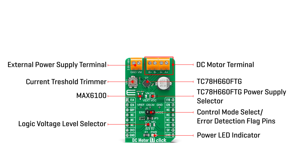
The pin labeled as ERR represents the Error Detection Flag. When TC78H660FTG detects some errors, the ERR pin outputs a low level to the peripheral block. In Normal status, since the internal MOSFET is OFF, the logic level of the ERR pin is equal to the MODE control voltage from outside. When some event like thermal shutdown or overcurrent occurs, the ERR pin will become low (the internal MOSFET is ON). When the error detection is released by reasserting the external power supply or setting the device to Standby Mode, ERR pins show Normal Status.
In the case of constant current control, the rate of Mixed Decay Mode, which determines the current ripple, is fixed to 37.5%. Peak current can be set by the voltage value of the VREF pin obtained by the MAX6100, a low-cost, low-dropout, micropower voltage reference IC from Maxim Integrated. This series-mode voltage reference draws the only 90μA of supply current and can source 5mA and sink 2mA of load current. The current threshold point for the VREF pin of the TC78H660FTG, alongside with MAX6100, can be set manually using an onboard trimmer labeled as VR1.
The DC Motor 17 Click Board™ communicates with MCU using several GPIO pins, as mentioned before in the product description. Also, this Click board™ has a Standby pin labeled as SBY routed to the CS pin of the mikroBUS™ socket used to switch to Standby mode by toggling the pin. When the SBY pin is low, TC78H660FTG stops supplying the power to the logic circuit.
What needs to be especially emphasized is the difference in DC Motor modes between IN and PHASE Input Modes. In addition to motor modes such as Forward, Reverse, Stop, and Standby, only IN Input Mode has another additional, Short Brake Mode. More information on the Motor Mode Selection can be found in the attached datasheet.
The DC Motor 17 Click Board™ is designed to be operated with both 3.3V and 5V logic voltage levels that can be selected via the VCC SEL jumper. It allows for both 3.3V and 5V capable MCUs to use the GPIO communication lines properly. Additionally, there is a possibility for motor driver power supply selection via jumper labeled as VM SEL to supply TC78H660FTG from an external input terminal in the range from 2.5 to 16V or with voltage levels used from mikroBUS™ power supply pins.
| Type | Brushed |
| Applications | Can be used for driving DC motors, controlling the direction of the rotation, as well as brake and regulate the motor current. |
| On-board modules | The DC Motor 17 Click Board™ is based on the TC78H660FTG, a dual H Bridge driver for one or two DC brushed motors that incorporates a DMOS with low on-resistance in output transistors from Toshiba Semiconductor. |
| Key Features | Built-in dual H Bridge, built-in sense resistor, multi error detect functions, error detection flag, selectable operating modes, and more. |
| Interface | GPIO,PWM |
| Compatibility | mikroBUS |
| Click board size | M (42.9 x 25.4 mm) |
| Input Voltage | 3.3V,5V,External |
This table shows how the pinout of the DC Motor 17 Click Board™ corresponds to the pinout on the mikroBUS™ socket (the latter shown in the two middle columns).
| Notes | Pin | Pin | Notes | ||||
|---|---|---|---|---|---|---|---|
| A Channel Input 1 | I1A | 1 | AN | PWM | 16 | I1B | B Channel Input 1 |
| A Channel Input 2 | I2A | 2 | RST | INT | 15 | I2B | B Channel Input 2 |
| Standby | SBY | 3 | CS | RX | 14 | NC | |
| NC | 4 | SCK | TX | 13 | NC | ||
| NC | 5 | MISO | SCL | 12 | NC | ||
| NC | 6 | MOSI | SDA | 11 | NC | ||
| Power Supply | 3.3V | 7 | 3.3V | 5V | 10 | 5V | Power Supply |
| Ground | GND | 8 | GND | GND | 9 | GND | Ground |
| Label | Name | Default | Description |
|---|---|---|---|
| LD1 | PWR | - | Power LED Indicator |
| JP1 | VCC SEL | Left | Logic Voltage Level Selection 3V3/5V: Left position 3V3, Right position 5V |
| JP2 | VM SEL | Right | Power Supply Voltage Selection VEXT/VCC: Left position VEXT, Right position VCC |
| VR1 | VR1 | - | Current Threshold Trimmer |
| Description | Min | Typ | Max | Unit |
|---|---|---|---|---|
| Supply Voltage VCC | -0.3 | - | 6 | V |
| Motor Supply Voltage VM | 2.5 | - | 16 | V |
| Maximum Output Current | - | 1.1 | 2 | A |
| PWM Frequency | - | - | 400 | kHz |
| Operating Temperature Range | -40 | - | +85 | °C |
We provide a library for the DC Motor 17 Click Board™ on our LibStock page, as well as a demo application (example), developed using MikroElektronika compilers. The demo can run on all the main MikroElektronika development boards.
This library contains API for DC Motor 17 Click driver.
dcmotor17_retval_t dcmotor17_stop ( dcmotor17_t *ctx, uint8_t sel_out ) - DC Motor 17 stop motor function.dcmotor17_retval_t dcmotor17_forward ( dcmotor17_t *ctx, uint8_t sel_out ) - DC Motor 17 forward function.dcmotor17_retval_t dcmotor17_reverse ( dcmotor17_t *ctx, uint8_t sel_out ) - DC Motor 17 reverse function.The application is composed of two sections :
void application_task ( void ) {
    log_printf( &logger, "----------------------------rn" );
    log_printf( &logger, "          Motor A           rn" );
    log_printf( &logger, "----------------------------rn" );
    log_printf( &logger, "  Start the motor forward.  rn" );
    dcmotor17_forward( &dcmotor17, DCMOTOR17_SEL_OUT_A );
    Delay_ms( 5000 );

    log_printf( &logger, "----------------------------rn" );
    log_printf( &logger, "       Stop the motor.      rn" );
    dcmotor17_stop( &dcmotor17, DCMOTOR17_SEL_OUT_A );
    Delay_ms( 2000 );

    log_printf( &logger, "----------------------------rn" );
    log_printf( &logger, "  Start the motor reverse.  rn" );
    dcmotor17_reverse( &dcmotor17, DCMOTOR17_SEL_OUT_A );
    Delay_ms( 5000 );

    log_printf( &logger, "----------------------------rn" );
    log_printf( &logger, "       Stop the motor.      rn" );
    dcmotor17_stop( &dcmotor17, DCMOTOR17_SEL_OUT_A );
    Delay_ms( 2000 );

    log_printf( &logger, "----------------------------rn" );
    log_printf( &logger, "          Motor B           rn" );
    log_printf( &logger, "----------------------------rn" );
    log_printf( &logger, "  Start the motor forward.  rn" );
    dcmotor17_forward( &dcmotor17, DCMOTOR17_SEL_OUT_B );
    Delay_ms( 5000 );

    log_printf( &logger, "----------------------------rn" );
    log_printf( &logger, "       Stop the motor.      rn" );
    dcmotor17_stop( &dcmotor17, DCMOTOR17_SEL_OUT_B );
    Delay_ms( 2000 );

    log_printf( &logger, "----------------------------rn" );
    log_printf( &logger, "  Start the motor reverse.  rn" );
    dcmotor17_reverse( &dcmotor17, DCMOTOR17_SEL_OUT_B );
    Delay_ms( 5000 );

    log_printf( &logger, "----------------------------rn" );
    log_printf( &logger, "       Stop the motor.      rn" );
    dcmotor17_stop( &dcmotor17, DCMOTOR17_SEL_OUT_B );
    Delay_ms( 2000 );
}
The full application code, and ready to use projects can be found on our LibStock page.
Other mikroE Libraries used in the example:
Depending on the development board you are using, you may need a USB UART click, USB UART 2 click or RS232 click to connect to your PC, for development systems with no UART to USB interface available on the board. The terminal available in all MikroElektronika compilers, or any other terminal application of your choice, can be used to read the message.
The DC Motor 17 Click Board™ is supported with mikroSDK - MikroElektronika Software Development Kit. To ensure proper operation of mikroSDK compliant Click board™ demo applications, mikroSDK should be downloaded from the LibStock and installed for the compiler you are using.
- attachments: [{"download_file":[{"download_file":"DC Motor 17 Click Board™ Schematic"}],"download_filetype":[{"download_filetype":"pdf"}]},{"download_file":[{"download_file":"Toshiba TC78H660FTG Dual H-Bridge Driver Datasheet"}],"download_filetype":[{"download_filetype":"pdf"}]},{"download_file":[{"download_file":"Maxim MAX6100 Voltage Reference Datasheer"}],"download_filetype":[{"download_filetype":"pdf"}]}] - condition: new - custom_product: false - mpn: MIKROE-4454 - google_product_category: Electronics - custom_label_0: Click Board - device_vendor: Toshiba Semiconductor and Storage - device_type: TC78H660FTG,EL - warranty: 12 months - brand: MikroE - key_feature_1: DC Motor Driver for One or Two DC Brushed Motors - manufacturer: Mikroelektronika d.o.o. - target_keyword: DC Motor 17 Click Board - brands: gid://shopify/Metaobject/56256004319 - breadcrumbs: ["gid://shopify/Collection/447955239135","gid://shopify/Collection/241680580797","gid://shopify/Collection/241545248957","gid://shopify/Collection/279405134013"] - customhs_code: 847330 - detailed_description: {"type":"root","children":[{"type":"heading","level":3,"children":[{"type":"text","value":"How Does The DC Motor 17 Click Board™ Work?"}]},{"type":"paragraph","children":[{"type":"text","value":"The "},{"type":"text","value":"DC Motor 17 Click Board™","bold":true,"italic":true},{"type":"text","value":" is based on the TC78H660FTG, a dual H Bridge driver for one or two DC brushed motors that incorporate a DMOS output transistor with low on-resistance from Toshiba Semiconductor. This driver is a PWM controlled constant-current drive with supply voltages from 2.5 to 16V and 2A of maximum output current. It features a built-in dual H-bridge, sense-resistor less current control architecture (advanced current detection system), and VCC regulator for the internal circuit. Besides, it offers thermal shutdown, overcurrent detection, Undervoltage lockout error detections (with error detection flag output function), and several selectable operational modes (Forward, Reverse, Stop, and Brake) controlled by four GPIO pins routed on the RST, AN, PWM, and INT pins of the mikroBUS™ socket."}]},{"type":"paragraph","children":[{"type":"text","value":""}]},{"type":"paragraph","children":[{"type":"text","value":"The TC78H660FTG possesses two operational modes, IN Input Mode and PHASE Input Mode, whose selection can be achieved via headers Control Mode pin labeled as MODE. PHASE Mode represents the default mode of the "},{"type":"text","value":"DC Motor 17 Click Board™","bold":true},{"type":"text","value":", and the Control Mode is set up by the input state of the MODE pin after releasing the SBY pin. This way, the MODE pin is used as the Enable signal while the direction selection is realized via GPIO pins routed on the mikroBUS™ socket."}]},{"type":"paragraph","children":[{"type":"text","value":"The pin labeled as ERR represents the Error Detection Flag. When TC78H660FTG detects some errors, the ERR pin outputs a low level to the peripheral block. In Normal status, since the internal MOSFET is OFF, the logic level of the ERR pin is equal to the MODE control voltage from outside. When some event like thermal shutdown or overcurrent occurs, the ERR pin will become low (the internal MOSFET is ON). When the error detection is released by reasserting the external power supply or setting the device to Standby Mode, ERR pins show Normal Status."}]},{"type":"paragraph","children":[{"type":"text","value":"In the case of constant current control, the rate of Mixed Decay Mode, which determines the current ripple, is fixed to 37.5%. Peak current can be set by the voltage value of the VREF pin obtained by the MAX6100, a low-cost, low-dropout, micropower voltage reference IC from Maxim Integrated. This series-mode voltage reference draws the only 90μA of supply current and can source 5mA and sink 2mA of load current. The current threshold point for the VREF pin of the TC78H660FTG, alongside with MAX6100, can be set manually using an onboard trimmer labeled as VR1."}]},{"type":"paragraph","children":[{"type":"text","value":"The "},{"type":"text","value":"DC Motor 17 Click Board™","bold":true},{"type":"text","value":" communicates with MCU using several GPIO pins, as mentioned before in the product description. Also, this Click board™ has a Standby pin labeled as SBY routed to the CS pin of the mikroBUS™ socket used to switch to Standby mode by toggling the pin. When the SBY pin is low, TC78H660FTG stops supplying the power to the logic circuit."}]},{"type":"paragraph","children":[{"type":"text","value":"What needs to be especially emphasized is the difference in DC Motor modes between IN and PHASE Input Modes. In addition to motor modes such as Forward, Reverse, Stop, and Standby, only IN Input Mode has another additional, Short Brake Mode. More information on the Motor Mode Selection can be found in the attached datasheet."}]},{"type":"paragraph","children":[{"type":"text","value":"The "},{"type":"text","value":"DC Motor 17 Click Board™","bold":true},{"type":"text","value":" is designed to be operated with both 3.3V and 5V logic voltage levels that can be selected via the VCC SEL jumper. It allows for both 3.3V and 5V capable MCUs to use the GPIO communication lines properly. Additionally, there is a possibility for motor driver power supply selection via jumper labeled as VM SEL to supply TC78H660FTG from an external input terminal in the range from 2.5 to 16V or with voltage levels used from mikroBUS™ power supply pins."}]},{"type":"heading","level":3,"children":[{"type":"text","value":"SPECIFICATIONS"}]},{"type":"paragraph","children":[{"type":"text","value":"Type\nBrushed\nApplications\nCan be used for driving DC motors, controlling the direction of the rotation, as well as brake and regulate the motor current.\nOn-board modules\nThe DC Motor 17 Click Board™ is based on the TC78H660FTG, a dual H Bridge driver for one or two DC brushed motors that incorporates a DMOS with low on-resistance in output transistors from Toshiba Semiconductor.\nKey Features\nBuilt-in dual H Bridge, built-in sense resistor, multi error detect functions, error detection flag, selectable operating modes, and more.\nInterface\nGPIO,PWM\nCompatibility\nmikroBUS\nClick board size\nM (42.9 x 25.4 mm)\nInput Voltage\n3.3V,5V,External"}]},{"type":"heading","level":3,"children":[{"type":"text","value":"PINOUT DIAGRAM"}]},{"type":"paragraph","children":[{"type":"text","value":"This table shows how the pinout of the "},{"type":"text","value":"DC Motor 17 Click Board™","bold":true},{"type":"text","value":" corresponds to the pinout on the mikroBUS™ socket (the latter shown in the two middle columns)."}]},{"type":"paragraph","children":[{"type":"text","value":"Notes\nPin\nPin\nNotes\nA Channel Input 1\nI1A\n1\nAN\nPWM\n16\nI1B\nB Channel Input 1\nA Channel Input 2\nI2A\n2\nRST\nINT\n15\nI2B\nB Channel Input 2\nStandby\nSBY\n3\nCS\nRX\n14\nNC\nNC\n4\nSCK\nTX\n13\nNC\nNC\n5\nMISO\nSCL\n12\nNC\nNC\n6\nMOSI\nSDA\n11\nNC\nPower Supply\n3.3V\n7\n3.3V\n5V\n10\n5V\nPower Supply\nGround\nGND\n8\nGND\nGND\n9\nGND\nGround"}]},{"type":"heading","level":3,"children":[{"type":"text","value":"ONBOARD SETTINGS AND INDICATORS"}]},{"type":"paragraph","children":[{"type":"text","value":"Label\nName\nDefault\n Description\nLD1\nPWR\n-\nPower LED Indicator\nJP1\nVCC SEL\nLeft\nLogic Voltage Level Selection 3V3/5V: Left position 3V3, Right position 5V\nJP2\nVM SEL\nRight\nPower Supply Voltage Selection VEXT/VCC: Left position VEXT, Right position VCC\nVR1\nVR1\n-\nCurrent Threshold Trimmer"}]},{"type":"heading","level":3,"children":[{"type":"text","value":"DC MOTOR 17 CLICK ELECTRICAL SPECIFICATIONS"}]},{"type":"paragraph","children":[{"type":"text","value":"Description\nMin\nTyp\nMax\nUnit\nSupply Voltage VCC\n-0.3\n-\n6\nV\nMotor Supply Voltage VM\n2.5\n-\n16\nV\nMaximum Output Current\n-\n1.1\n2\nA\nPWM Frequency\n-\n-\n400\nkHz\nOperating Temperature Range\n-40\n-\n+85\n°C"}]},{"type":"heading","level":3,"children":[{"type":"text","value":" "}]}]} - summary:The DC Motor 17 Click™ Board is a compact add-on board that contains a brushed DC motor driver. This board features the TC78H660FTG, a dual H Bridge driver for one or two brushed motors that incorporate a DMOS output transistor with low on-resistance from Toshiba Semiconductor. This IC is a PWM controlled constant-current drive with supply voltages from 2.5V to 16V and 2A of output current. It features a sense-resistor less current control architecture and VCC regulator for the internal circuit. Also offers multi-error detect functions with error detection flag output function. This Click Board™ is suitable for driving DC motors, controlling the direction of the rotation, as well as brake and regulating the motor current.
The DC Motor 17 Click Board™ is supported by a mikroSDK compliant library, which includes functions that simplify software development. This Click Board™ comes as a fully tested product, ready to be used on a system equipped with the mikroBUS™ socket.