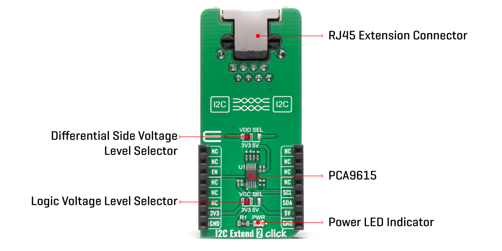
The I2C Extend 2 Click Board™ is based on the PCA9615, a Fast-Mode Plus (FM+) I2C bus buffer that extends the single-ended I2C bus through electrically noisy environments from NXP Semiconductor. It consists of two single-ended to differential driver channels for the SCL (Serial Clock) and SDA (Serial Data). The use of differential transmission lines between identical I2C bus buffers removes electrical noise and common-mode offsets that are present when signal lines must pass between different voltage domains, such as high energy power supplies and electric motors. Those signals can reach distances of up to 3m or longer at lower clock speeds while maintaining signal integrity sent over an Ethernet cable (a twisted-pair transmission line cable) through the onboard RJ-45 connector.
The PCA9615 converts the two default I2C signals into four differential signals, two for SCL and two for SDA. The signal direction is determined by the I2C protocol, which means it does not require a direction signal, as these bus buffers automatically set signal flow direction. Additional circuitry allows the PCA9615 to be used for 'hot-swap' applications, where systems are always ON but require insertion or removal of modules or cards without disruption to existing signals. Because the supply voltages on the I2C bus side may be different from the external I2C bus side, there are two power supply pins and common ground. First is a standard I2C bus side power supply selected via the VCC SEL jumper, and the other represents the majority supply for circuitry determined by the VDD SEL jumper.
The I2C Extend 2 Click Board™ communicates with MCU using the standard I2C interface with a frequency up to 100kHz in the Standard and 400kHz in the Fast Mode, and up to 1MHz in the Fast Mode Plus. The user must be cautious not to overload the driver's current rating of 3mA for Standard and Fast Modes and 30mA for Fast Mode Plus (FM+). Also, this Click board™ has an Enable pin, routed on the CS pin of the mikroBUS™ socket labelled as EN, used to disable the bus buffer, and is useful for fault finding, Power-Up sequencing, or re-configuration of a bus system by isolating sections not needed at all times.
The I2C Extend 2 Click Board™ is designed to operate with both 3.3V and 5V logic voltage levels selected via the VCC SEL jumper. It allows for both 3.3V and 5V capable MCUs to use the I2C communication lines properly. However, the Click board™ comes equipped with a library that contains easy to use functions and an example code which can be used, as a reference, for further development.
| Type | I2C |
| Applications | Can be used for various applications that require extending the I2C bus over a long distance, such as commercial lighting and industrial control, control of power supplies in a high noise environment, and more. |
| On-board modules | IThe I2C Extend 2 Click Board™ is based on the PCA9615, a Fast-Mode Plus (FM+) I2C bus buffer that extends the single-ended I2C bus through electrically noisy environments from NXP Semiconductor. |
| Key Features | Low power consumption, improved resistance to system noise, hot swap, supports arbitration and clock stretching, bus idle detect, and more. |
| Interface | I2C |
| Compatibility | mikroBUS |
| Click board size | L (57.15 x 25.4 mm) |
| Input Voltage | 3.3V or 5V |
This table shows how the pinout of the I2C Extend 2 Click Board™ corresponds to the pinout on the mikroBUS™ socket (the latter shown in the two middle columns).
| Notes | Pin | Pin | Notes | ||||
|---|---|---|---|---|---|---|---|
| NC | 1 | AN | PWM | 16 | NC | ||
| NC | 2 | RST | INT | 15 | NC | ||
| Enable | EN | 3 | CS | RX | 14 | NC | |
| NC | 4 | SCK | TX | 13 | NC | ||
| NC | 5 | MISO | SCL | 12 | SCL | I2C Clock | |
| NC | 6 | MOSI | SDA | 11 | SDA | I2C Data | |
| Power Supply | 3.3V | 7 | 3.3V | 5V | 10 | 5V | Power Supply |
| Ground | GND | 8 | GND | GND | 9 | GND | Ground |
| Label | Name | Default | Description |
|---|---|---|---|
| LD1 | PWR | - | Power LED Indicator |
| JP1 | VCC SEL | Left | Power Supply Voltage Selection 3V3/5V: Left position 3V3, Right position 5V |
| JP2 | VDD SEL | Left | Differential Side Voltage Selection 3V3/5V: Left position 3V3, Right position 5V |
| Description | Min | Typ | Max | Unit |
|---|---|---|---|---|
| Supply Voltage | -0.5 | - | 6 | V |
| Maximum Output Current | - | - | 80 | mA |
| Data Rate | - | - | 1 | MHz |
| Operating Temperature Range | -40 | - | +85 | °C |
We provide a library for the I2C Extend 2 Click Board™ on our LibStock page, as well as a demo application (example), developed using MikroElektronika compilers. The demo can run on all the main MikroElektronika development boards.
The library covers all the necessary functions to control I2C Extend 2 Click board™. Library performs a standard I2C interface communication.
void i2cextend2_rmt_write ( uint8_t rmt_slave_addr, uint8_t reg, uint8_t tx_data ) - Generic write data to the remote device function.uint8_t i2cextend2_rmt_read ( uint8_t rmt_slave_addr, uint8_t reg ) - Generic read data from the remote device function.void i2cextend2_enable ( uint8_t en_extend ) - Enable extend function.The application is composed of three sections :
void application_task ( )
{
 mikrobus_logWrite( " Accel | Mag ", _LOG_LINE );
 mikrobus_logWrite( "------------------------", _LOG_LINE );
 i2cextend2_6dofimu11_get_axis( C6DOFIMU11_REG_ACCEL_XOUT_L );
 mikrobus_logWrite( " X :", _LOG_TEXT );
 IntToStr( axis, log_text );
 mikrobus_logWrite( log_text, _LOG_TEXT );
 mikrobus_logWrite( " | ", _LOG_TEXT );
 i2cextend2_6dofimu11_get_axis( C6DOFIMU11_REG_MAG_XOUT_L );
 mikrobus_logWrite( " X :", _LOG_TEXT );
 IntToStr( axis, log_text );
 mikrobus_logWrite( log_text, _LOG_LINE );
 i2cextend2_6dofimu11_get_axis( C6DOFIMU11_REG_ACCEL_YOUT_L );
 mikrobus_logWrite( " Y :", _LOG_TEXT );
 IntToStr( axis, log_text );
 mikrobus_logWrite( log_text, _LOG_TEXT );
 mikrobus_logWrite( " | ", _LOG_TEXT );
 i2cextend2_6dofimu11_get_axis( C6DOFIMU11_REG_MAG_YOUT_L );
 mikrobus_logWrite( " Y :", _LOG_TEXT );
 IntToStr( axis, log_text );
 mikrobus_logWrite( log_text, _LOG_LINE );
 i2cextend2_6dofimu11_get_axis( C6DOFIMU11_REG_ACCEL_ZOUT_L );
 mikrobus_logWrite( " Z :", _LOG_TEXT );
 IntToStr( axis, log_text );
 mikrobus_logWrite( log_text, _LOG_TEXT );
 mikrobus_logWrite( " | ", _LOG_TEXT );
 i2cextend2_6dofimu11_get_axis( C6DOFIMU11_REG_MAG_ZOUT_L );
 mikrobus_logWrite( " Z :", _LOG_TEXT );
 IntToStr( axis, log_text );
 mikrobus_logWrite( log_text, _LOG_LINE );
 mikrobus_logWrite( "------------------------", _LOG_LINE );
 Delay_ms( 1000 );
}
void i2cextend2_6dofimu11_get_axis ( uint8_t axis_out_reg ) - Read axis.The full application code, and ready to use projects can be found on our LibStock page.
Other mikroE Libraries used in the example:
Depending on the development board you are using, you may need USB UART Click Board™, USB UART 2 Click Board™ or RS232 Click Board™ to connect to your PC, for development systems with no UART to USB interface available on the board. The terminal available in all MikroElektronika compilers, or any other terminal application of your choice, can be used to read the message.
The I2C Extend 2 Click Board™ is supported with mikroSDK - MikroElektronika Software Development Kit. To ensure proper operation of mikroSDK compliant Click board™ demo applications, mikroSDK should be downloaded from the LibStock and installed for the compiler you are using.
- attachments: [{"download_file":[{"download_file":"I2C Extend 2 Click Board™ Schematic"}],"download_filetype":[{"download_filetype":"pdf"}]},{"download_file":[{"download_file":"NXP PCA9615 I2C Bus Buffer Datasheet"}],"download_filetype":[{"download_filetype":"pdf"}]}] - myordercount: {"ordercount":2,"recentcount":2} - device_vendor: NXP USA Inc. - device_type: PCA9615DPJ - warranty: 12 months - brand: MikroE - key_feature_1: Extends I2C Interface to over 3m - manufacturer: Mikroelektronika d.o.o. - target_keyword: I2C Extend 2 Click Board - brands: gid://shopify/Metaobject/56256004319 - breadcrumbs: ["gid://shopify/Collection/447955239135","gid://shopify/Collection/241680580797","gid://shopify/Collection/241546100925"] - customhs_code: 847330 - detailed_description: {"type":"root","children":[{"type":"heading","level":3,"children":[{"type":"text","value":"How Does The I2C Extend 2 Click Board™ Work?"}]},{"type":"paragraph","children":[{"type":"text","value":"The"},{"type":"text","value":" I2C Extend 2 Click Board™","bold":true},{"type":"text","value":" is based on the PCA9615, a Fast-Mode Plus (FM+) I2C bus buffer that extends the single-ended I2C bus through electrically noisy environments from NXP Semiconductor. It consists of two single-ended to differential driver channels for the SCL (Serial Clock) and SDA (Serial Data). The use of differential transmission lines between identical I2C bus buffers removes electrical noise and common-mode offsets that are present when signal lines must pass between different voltage domains, such as high energy power supplies and electric motors. Those signals can reach distances of up to 3m or longer at lower clock speeds while maintaining signal integrity sent over an Ethernet cable (a twisted-pair transmission line cable) through the onboard RJ-45 connector."}]},{"type":"paragraph","children":[{"type":"text","value":""}]},{"type":"paragraph","children":[{"type":"text","value":"The PCA9615 converts the two default I2C signals into four differential signals, two for SCL and two for SDA. The signal direction is determined by the I2C protocol, which means it does not require a direction signal, as these bus buffers automatically set signal flow direction. Additional circuitry allows the PCA9615 to be used for 'hot-swap' applications, where systems are always ON but require insertion or removal of modules or cards without disruption to existing signals. Because the supply voltages on the I2C bus side may be different from the external I2C bus side, there are two power supply pins and common ground. First is a standard I2C bus side power supply selected via the VCC SEL jumper, and the other represents the majority supply for circuitry determined by the VDD SEL jumper."}]},{"type":"paragraph","children":[{"type":"text","value":"The "},{"type":"text","value":"I2C Extend 2 Click Board™","bold":true},{"type":"text","value":" communicates with MCU using the standard I2C interface with a frequency up to 100kHz in the Standard and 400kHz in the Fast Mode, and up to 1MHz in the Fast Mode Plus. The user must be cautious not to overload the driver's current rating of 3mA for Standard and Fast Modes and 30mA for Fast Mode Plus (FM+). Also, this Click board™ has an Enable pin, routed on the CS pin of the mikroBUS™ socket labelled as EN, used to disable the bus buffer, and is useful for fault finding, Power-Up sequencing, or re-configuration of a bus system by isolating sections not needed at all times."}]},{"type":"paragraph","children":[{"type":"text","value":"The "},{"type":"text","value":"I2C Extend 2 Click Board™","bold":true},{"type":"text","value":" is designed to operate with both 3.3V and 5V logic voltage levels selected via the VCC SEL jumper. It allows for both 3.3V and 5V capable MCUs to use the I2C communication lines properly. However, the Click board™ comes equipped with a library that contains easy to use functions and an example code which can be used, as a reference, for further development."}]},{"type":"heading","level":3,"children":[{"type":"text","value":"SPECIFICATIONS"}]},{"type":"paragraph","children":[{"type":"text","value":"Type\nI2C\nApplications\nCan be used for various applications that require extending the I2C bus over a long distance, such as commercial lighting and industrial control, control of power supplies in a high noise environment, and more.\nOn-board modules\nIThe I2C Extend 2 Click Board™ is based on the PCA9615, a Fast-Mode Plus (FM+) I2C bus buffer that extends the single-ended I2C bus through electrically noisy environments from NXP Semiconductor.\nKey Features\nLow power consumption, improved resistance to system noise, hot swap, supports arbitration and clock stretching, bus idle detect, and more.\nInterface\nI2C\nCompatibility\nmikroBUS\nClick board size\nL (57.15 x 25.4 mm)\nInput Voltage\n3.3V or 5V"}]},{"type":"heading","level":3,"children":[{"type":"text","value":"PINOUT DIAGRAM"}]},{"type":"paragraph","children":[{"type":"text","value":"This table shows how the pinout of the "},{"type":"text","value":"I2C Extend 2 Click Board™","bold":true},{"type":"text","value":" corresponds to the pinout on the mikroBUS™ socket (the latter shown in the two middle columns)."}]},{"type":"paragraph","children":[{"type":"text","value":"Notes\nPin\nPin\nNotes\nNC\n1\nAN\nPWM\n16\nNC\nNC\n2\nRST\nINT\n15\nNC\nEnable\nEN\n3\nCS\nRX\n14\nNC\nNC\n4\nSCK\nTX\n13\nNC\nNC\n5\nMISO\nSCL\n12\nSCL\nI2C Clock\nNC\n6\nMOSI\nSDA\n11\nSDA\nI2C Data\nPower Supply\n3.3V\n7\n3.3V\n5V\n10\n5V\nPower Supply\nGround\nGND\n8\nGND\nGND\n9\nGND\nGround"}]},{"type":"heading","level":3,"children":[{"type":"text","value":"ONBOARD SETTINGS AND INDICATORS"}]},{"type":"paragraph","children":[{"type":"text","value":"Label\nName\nDefault\nDescription\nLD1\nPWR\n-\nPower LED Indicator\nJP1\nVCC SEL\nLeft\nPower Supply Voltage Selection 3V3/5V: Left position 3V3, Right position 5V\nJP2\nVDD SEL\nLeft\nDifferential Side Voltage Selection 3V3/5V: Left position 3V3, Right position 5V"}]},{"type":"heading","level":3,"children":[{"type":"text","value":"I2C EXTEND 2 CLICK ELECTRICAL SPECIFICATIONS"}]},{"type":"paragraph","children":[{"type":"text","value":"Description\nMin\nTyp\nMax\nUnit\nSupply Voltage\n-0.5\n-\n6\nV\nMaximum Output Current\n-\n-\n80\nmA\nData Rate\n-\n-\n1\nMHz\nOperating Temperature Range\n-40\n-\n+85\n°C"}]},{"type":"heading","level":3,"children":[{"type":"text","value":" "}]}]} - summary:The I2C Extend 2 Click Board™ is a compact add-on board suitable for I2C communication bus extension. This board features the PCA9615, a 2-channel multipoint differential I2C bus buffer with hot-swap logic from NXP Semiconductors. The PCA9615 converts the two default I2C signals into four differential signals, two for SCL and two for SDA. The differential signals allow the I2C signals to reach distances of up to 3m while maintaining their signal integrity sent over an Ethernet cable through the onboard RJ-45 connector. This Click Board™ is suitable for various applications that require extending the I2C bus over a long distance, such as commercial lighting and industrial control, control of power supplies in a high noise environment, and more.
The I2C Extend 2 Click Board™ is supported by a mikroSDK compliant library, which includes functions that simplify software development. This Click Board™ comes as a fully tested product, ready to be used on a system equipped with the mikroBUS™ socket.