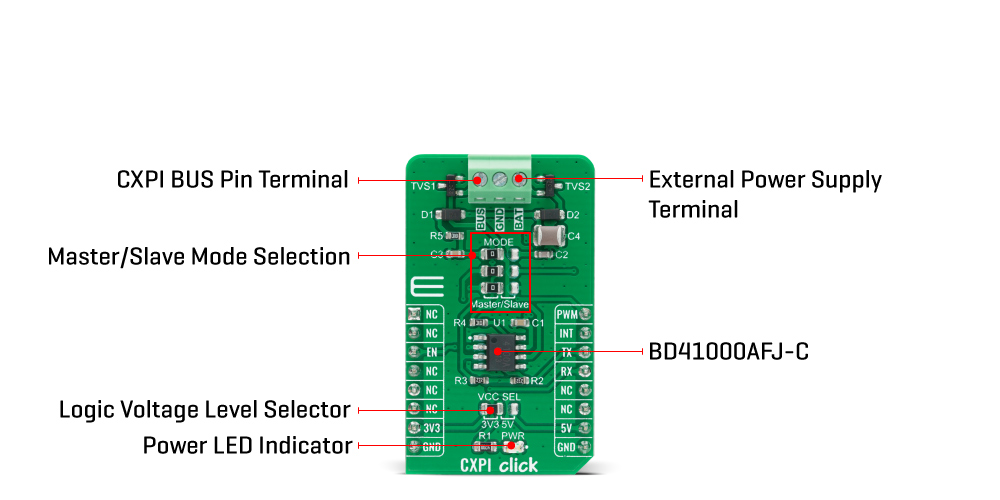
The CXPI Click Board™ is based on the BD41000AFJ-C, a transceiver for the Clock Extension Peripheral Interface (CXPI) communication from Rohm Semiconductor. The BD41000FJ-C is compliant with the CXPI standard established by JSAE (Society of Automotive Engineers of Japan), enabling highly responsive, reliable multiplex communication even in HMI systems, reducing vehicle weight and contributing to greater fuel efficiency. The BD41000AFJ-C operates from 7V to 18V external power supply labeled as BAT, and has several operating modes each controlled by the CS pin of the mikroBUS™, BUS pin, and UART TX pin.
It has built-in Power-OFF, Through, RX Through other than CODEC Mode for power saving control. Power-OFF Mode reduces power consumption by not supplying power to any circuits other than necessary ones for Wake-Up pulse detection (BUS) and Wake-Up input detection (TX). Through Mode does not process Coding/Decoding. It only drives signals from UART TX to BUS and from BUS to UART RX directly. RX Through Mode reverses RX output at each rising edge of BUS. CODEC Mode is the mode of CXPI communication. CS pin of the mikroBUS™ socket labeled as EN should be set high for the chip to enter CODEC Mode.
The BD41000AFJ-C can achieve a quiescent current of 3uA (typ.), ensuring suitability with automotive applications. As a result, the battery load is minimized during non-operation, contributing to higher energy savings. Also, high ESD resistance (±8kV) makes it possible to achieve low-power, high-reliability CXPI communication. Besides, it has built-in fail-safe functions that suspend the output data upon detection of under-voltage or temperature abnormality.
The CXPI Click Board™ communicates with MCU using the UART interface with a transmission speed range from 5kbps to 20kbps, and commonly used UART RX and TX pins for the data transfer. Also, it has three jumpers that allow the selection of CXPI transmitter mode on the MS pin of the BD41000AFJ-C to its appropriate position marked as Master or Slave. This can be performed by using the SMD jumpers labeled as MODE. Note that all the jumpers must be placed to the same side, or else the Click board™ may become unresponsive.
The CXPI Click Board™ is designed to be operated with both 3.3V and 5V logic voltage levels that can be selected via VCC SEL jumper. This allows for both 3.3V and 5V capable MCUs to use the UART communication lines properly. However, the Click board™ comes equipped with a library that contains easy to use functions and an example code that can be used as a reference for further development.
| Type | CXPI |
| Applications | Can be used in body control applications, including steering switch, AC, and instrument panel systems. |
| On-board modules | The CXPI Click Board™ is based on the BD41000AFJ-C, a transceiver for the Clock Extension Peripheral Interface (CXPI) communication from Rohm Semiconductor. |
| Key Features | CXPI standards qualified, transmission speed range from 5kbps to 20kbps, Master/Slave switching function, power saving function, data arbitration function, built-in UVLO and TDS function, and more. |
| Interface | PWM,UART |
| Compatibility | mikroBUS |
| Click board size | M (42.9 x 25.4 mm) |
| Input Voltage | 3.3V or 5V |
This table shows how the pinout on CXPI Click Board™ corresponds to the pinout on the mikroBUS™ socket (the latter shown in the two middle columns).
| Notes | Pin | Pin | Notes | ||||
|---|---|---|---|---|---|---|---|
| NC | 1 | AN | PWM | 16 | PWM | Master Mode: Clock Input | |
| NC | 2 | RST | INT | 15 | INT | Slave Mode: Clock Output | |
| Enable | EN | 3 | CS | RX | 14 | RX | UART RX |
| NC | 4 | SCK | TX | 13 | TX | UART TX | |
| NC | 5 | MISO | SCL | 12 | NC | ||
| NC | 6 | MOSI | SDA | 11 | NC | ||
| Power Supply | 3.3V | 7 | 3.3V | 5V | 10 | 5V | Power Supply |
| Ground | GND | 8 | GND | GND | 9 | GND | Ground |
| Label | Name | Default | Description |
|---|---|---|---|
| LD1 | PWR | - | Power LED Indicator |
| JP1 | VCC SEL | Left | Power Supply Voltage Selection 3V3/5V: Left position 3V3, Right position 5V |
| JP2-JP4 | MODE | Left | Master/Slave Mode Selection: Left position Master, Right position Slave |
| Description | Min | Typ | Max | Unit |
|---|---|---|---|---|
| Supply Voltage VCC | -0.3 | - | 7 | V |
| Supply Voltage BAT | 7 | - | 18 | V |
| Data Rates | 5 | - | 20 | kbps |
| Power Saving Mode Current | - | - | 10 | μA |
| Operating Temperature Range | -40 | - | +125 | °C |
The 16x9 G Click Board™ contains a green LED matrix and the IS31FL3731 audio modulated matrix LED driver. The dimension of the LED matrix is 16x9. Each LED can be controlled individually ,
- amazon_main_image: https://www.thedebugstore.com/images/product/lg-16x9-g-front_1.jpg - amazon_other_image_1: https://www.thedebugstore.com/images/product/lg-16x9-g-back_1.jpg - amazon_other_image_2: https://www.thedebugstore.com/images/product/lg-16x9-g-click_1.jpg - amazon_other_image_3: https://www.thedebugstore.com/images/product/lg-16x9-g-click_1.jpg - amazon_browse_node: 428655031 - related_products: MIKROE-2758,MIKROE-4331,MIKROE-1438 - mpn: MIKROE-4336 - backorder_label: If no stock shown above, check availability - badge: - widget:We provide a library for the CXPI Click Board™ on our LibStock page, as well as a demo application (example), developed using MikroElektronika compilers. The demo can run on all the main MikroElektronika development boards.
The library covers all the necessary functions to control the CXPI Click Board™. Library performs a standard UART communication.
void cxpi_write_byte ( uint8_t input ) - Write Single Byte.uint8_t cxpi_read_byte ( void ) - Read Single Byte.uint8_t cxpi_byte_ready ( void ) - Check for new byte received.The application is composed of three sections :
void application_task ( )
{
 if ( app_mode == APP_MODE_TRANSMITER )
 {
 mikrobus_logWrite( "----------------------", _LOG_LINE );
 mikrobus_logWrite( "", _LOG_LINE );
 cxpi_write_data( &demo_message_data[ 0 ], 9 );
 mikrobus_logWrite( " TX Data: ", _LOG_TEXT );
 mikrobus_logWrite( demo_message_data, _LOG_LINE );
 Delay_ms( 5000 );
 }
}
The full application code, and ready to use projects can be found on our LibStock page.
Other mikroE Libraries used in the example:
Depending on the development board you are using, you may need USB UART click, USB UART 2 click or RS232 click to connect to your PC, for development systems with no UART to USB interface available on the board. The terminal available in all MikroElektronika compilers, or any other terminal application of your choice, can be used to read the message.
The CXPI Click Board™ is supported with mikroSDK - MikroElektronika Software Development Kit. To ensure proper operation of mikroSDK compliant Click board™ demo applications, mikroSDK should be downloaded from the LibStock and installed for the compiler you are using.
- attachments: [{"download_file":[{"download_file":"CXPI Click Board™ Schematic"}]},{"download_file":[{"download_file":"Rohm Semiconductor BD41000AFJ-C CXPI Transceiver Datasheet"}]}] - condition: new - custom_product: false - mpn: MIKROE-4336 - google_product_category: Electronics - custom_label_0: Click Board - device_vendor: Rohm Semiconductor - device_type: BD41000AFJ-CE2 - warranty: 12 months - brand: MikroE - key_feature_1: Supports CXPI, The Next Generation Automotive Interface - manufacturer: Mikroelektronika d.o.o. - target_keyword: CXPI Click Board - brands: gid://shopify/Metaobject/56256004319 - breadcrumbs: ["gid://shopify/Collection/447955239135","gid://shopify/Collection/241680580797","gid://shopify/Collection/241546100925"] - customhs_code: 847330 - detailed_description: {"type":"root","children":[{"type":"heading","level":3,"children":[{"type":"text","value":"How Does The CXPI Click Board™ Work?"}]},{"type":"paragraph","children":[{"type":"text","value":"The "},{"type":"text","value":"CXPI Click Board™","bold":true,"italic":true},{"type":"text","value":" is based on the BD41000AFJ-C, a transceiver for the Clock Extension Peripheral Interface (CXPI) communication from Rohm Semiconductor. The BD41000FJ-C is compliant with the CXPI standard established by JSAE (Society of Automotive Engineers of Japan), enabling highly responsive, reliable multiplex communication even in HMI systems, reducing vehicle weight and contributing to greater fuel efficiency. The BD41000AFJ-C operates from 7V to 18V external power supply labeled as BAT, and has several operating modes each controlled by the CS pin of the mikroBUS™, BUS pin, and UART TX pin."}]},{"type":"paragraph","children":[{"type":"text","value":""}]},{"type":"paragraph","children":[{"type":"text","value":"It has built-in Power-OFF, Through, RX Through other than CODEC Mode for power saving control. Power-OFF Mode reduces power consumption by not supplying power to any circuits other than necessary ones for Wake-Up pulse detection (BUS) and Wake-Up input detection (TX). Through Mode does not process Coding/Decoding. It only drives signals from UART TX to BUS and from BUS to UART RX directly. RX Through Mode reverses RX output at each rising edge of BUS. CODEC Mode is the mode of CXPI communication. CS pin of the mikroBUS™ socket labeled as EN should be set high for the chip to enter CODEC Mode."}]},{"type":"paragraph","children":[{"type":"text","value":"The BD41000AFJ-C can achieve a quiescent current of 3uA (typ.), ensuring suitability with automotive applications. As a result, the battery load is minimized during non-operation, contributing to higher energy savings. Also, high ESD resistance (±8kV) makes it possible to achieve low-power, high-reliability CXPI communication. Besides, it has built-in fail-safe functions that suspend the output data upon detection of under-voltage or temperature abnormality."}]},{"type":"paragraph","children":[{"type":"text","value":"The "},{"type":"text","value":"CXPI Click Board™","bold":true},{"type":"text","value":" communicates with MCU using the UART interface with a transmission speed range from 5kbps to 20kbps, and commonly used UART RX and TX pins for the data transfer. Also, it has three jumpers that allow the selection of CXPI transmitter mode on the MS pin of the BD41000AFJ-C to its appropriate position marked as Master or Slave. This can be performed by using the SMD jumpers labeled as MODE. Note that all the jumpers must be placed to the same side, or else the Click board™ may become unresponsive."}]},{"type":"paragraph","children":[{"type":"text","value":"The "},{"type":"text","value":"CXPI Click Board™","bold":true},{"type":"text","value":" is designed to be operated with both 3.3V and 5V logic voltage levels that can be selected via VCC SEL jumper. This allows for both 3.3V and 5V capable MCUs to use the UART communication lines properly. However, the Click board™ comes equipped with a library that contains easy to use functions and an example code that can be used as a reference for further development."}]},{"type":"heading","level":3,"children":[{"type":"text","value":"SPECIFICATIONS"}]},{"type":"paragraph","children":[{"type":"text","value":"Type\nCXPI\nApplications\nCan be used in body control applications, including steering switch, AC, and instrument panel systems.\nOn-board modules\nThe CXPI Click Board™ is based on the BD41000AFJ-C, a transceiver for the Clock Extension Peripheral Interface (CXPI) communication from Rohm Semiconductor.\nKey Features\nCXPI standards qualified, transmission speed range from 5kbps to 20kbps, Master/Slave switching function, power saving function, data arbitration function, built-in UVLO and TDS function, and more.\nInterface\nPWM,UART\nCompatibility\nmikroBUS\nClick board size\nM (42.9 x 25.4 mm)\nInput Voltage\n3.3V or 5V"}]},{"type":"heading","level":3,"children":[{"type":"text","value":"PINOUT DIAGRAM"}]},{"type":"paragraph","children":[{"type":"text","value":"This table shows how the pinout on "},{"type":"text","value":"CXPI Click Board™","bold":true},{"type":"text","value":" corresponds to the pinout on the mikroBUS™ socket (the latter shown in the two middle columns)."}]},{"type":"paragraph","children":[{"type":"text","value":"Notes\nPin\nPin\nNotes\nNC\n1\nAN\nPWM\n16\nPWM\nMaster Mode: Clock Input\nNC\n2\nRST\nINT\n15\nINT\nSlave Mode: Clock Output\nEnable\nEN\n3\nCS\nRX\n14\nRX\nUART RX\nNC\n4\nSCK\nTX\n13\nTX\nUART TX\nNC\n5\nMISO\nSCL\n12\nNC\nNC\n6\nMOSI\nSDA\n11\nNC\nPower Supply\n3.3V\n7\n3.3V\n5V\n10\n5V\nPower Supply\nGround\nGND\n8\nGND\nGND\n9\nGND\nGround"}]},{"type":"heading","level":3,"children":[{"type":"text","value":"ONBOARD SETTINGS AND INDICATORS"}]},{"type":"paragraph","children":[{"type":"text","value":"Label\nName\nDefault\n Description\nLD1\nPWR\n-\nPower LED Indicator\nJP1\nVCC SEL\nLeft\nPower Supply Voltage Selection 3V3/5V: Left position 3V3, Right position 5V\nJP2-JP4\nMODE\nLeft\nMaster/Slave Mode Selection: Left position Master, Right position Slave"}]},{"type":"heading","level":3,"children":[{"type":"text","value":"CXPI CLICK ELECTRICAL SPECIFICATIONS"}]},{"type":"paragraph","children":[{"type":"text","value":"Description\nMin\nTyp\nMax\nUnit\nSupply Voltage VCC\n-0.3\n-\n7\nV\nSupply Voltage BAT\n7\n-\n18\nV\nData Rates\n5\n-\n20\nkbps\nPower Saving Mode Current\n-\n-\n10\nμA\nOperating Temperature Range\n-40\n-\n+125\n°C"}]},{"type":"heading","level":3,"children":[{"type":"text","value":" "}]}]} - summary:The CXPI Click Board™ is a compact add-on board that contains a transceiver that supports the next-generation automotive communication protocol. This board features the BD41000AFJ-C, a transceiver for the CXPI (Clock Extension Peripheral Interface) communication from Rohm Semiconductor. It operates from 7V to 18V external power supply, features easy switching between Master or Slave Mode, arbitration function that stops the data output upon detection of BUS data collision, and fail-safe functions that suspend the output data upon detection of under-voltage or temperature abnormality. This Click Board™ is suitable for use in body control applications, including steering switch, AC, and instrument panel systems.
The CXPI Click Board™ is supported by a mikroSDK compliant library, which includes functions that simplify software development. This Click Board™ comes as a fully tested product, ready to be used on a system equipped with the mikroBUS™ socket.