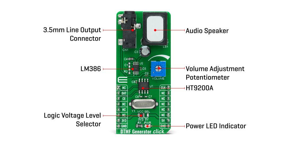
The DTMF Generator Click Board™ is based on the HT9200A, a dual-tone multi-frequency decoder designed for mobile communication systems from Holtek Semiconductor Inc.. The HT9200A is an SMD tone generator IC designed for MCU interfaces. It can be instructed by an MCU to generate 16 dual tones and 8 single tones from the DTMF pin, and it provides a Serial Mode. The system oscillator of HT9200A consists of an inverter, a bias resistor, and the required load capacitor on a chip. The oscillator function is implemented with a standard 3.579545MHz crystal connected to the X1 and X2 pins of the HT9200A.
The operation of the HT9200A is based on GPIO signals fed from the mikroBUS™ to the decoder, DAT and CLK. There is a connection between the digital codes and the tone output frequency based on which the desired output frequency is selected. The HT9200A employs a data input, a 5-bit code, and a synchronous clock to transmit a DTMF signal. Every digit of a transferred number is selected by a series of combinations that consist of 5-bit data. The HT9200A will latch data on the falling edge of the CLK pin and display the output data on its output DTMF pin. Then such a signal, via a volume adjustment potentiometer, is sent to an audio amplifier, the LM386 from Texas Instruments that represents a mono low-voltage amplifier that can be used in a variety of applications. After the audio amplifier, the desired sound can be detected on the on-board speaker.
The DTMF Generator Click Board™ communicates with MCU using three GPIO pins routed on the CS, RST, and PWM pins of the mikroBUS™ socket labelled as CE, DAT, and CLK. CE pin represents Chip Enable function used to Wake-Up the HT9200A, while DAT and CLK pins stand for data input and data synchronous clock input. It also possesses the adjustable potentiometer labelled as VOLUME that serves to adjust the volume of that signal. It also has a 3.5mm jack output connector that allows the user to use the output DTMF signal in their projects in their own way, whiles the signal volume still can be adjusted on the VOLUME potentiometer located on the DTMF Generator Click.
The DTMF Generator Click Board™ is designed to be operated with both 3.3V and 5V logic voltage levels that can be selected via VCC SEL jumper. This allows for both 3.3V and 5V capable MCUs to use the GPIO communication lines properly. However, the Click board™ comes equipped with a library that contains easy to use functions and an example code that can be used as a reference for further development.
| Type | Signal Processing |
| Applications | Can be used for various applications such as security systems, home automation, remote control through telephone lines, communication systems, and more. |
| On-board modules | The DTMF Generator Click Board™ is based on the HT9200A, a dual-tone multi-frequency decoder designed for mobile communication systems from Holtek Semiconductor Inc.. |
| Key Features | Dual-tone multi-frequency decoder, serial mode, low stand-by current, low total harmonic distortion, and more. |
| Interface | GPIO |
| Compatibility | mikroBUS |
| Click board size | L (57.15 x 25.4 mm) |
| Input Voltage | 3.3V or 5V |
This table shows how the pinout of the DTMF Generator Click Board™ corresponds to the pinout on the mikroBUS™ socket (the latter shown in the two middle columns).
| Notes | Pin | Pin | Notes | ||||
|---|---|---|---|---|---|---|---|
| NC | 1 | AN | PWM | 16 | CLK | Data Synchronous Clock Input |
|
| Data Input | DAT | 2 | RST | INT | 15 | NC | |
| Chip Enable | CE | 3 | CS | RX | 14 | NC | |
| NC | 4 | SCK | TX | 13 | NC | ||
| NC | 5 | MISO | SCL | 12 | NC | ||
| NC | 6 | MOSI | SDA | 11 | NC | ||
| Power Supply | 3.3V | 7 | 3.3V | 5V | 10 | 5V | Power Supply |
| Ground | GND | 8 | GND | GND | 9 | GND | Ground |
| Label | Name | Default | Description |
|---|---|---|---|
| LD1 | PWR | - | Power LED Indicator |
| JP1 | VCC SEL | Left | Power Supply Voltage Selection 3V3/5V: Left position 3V3, Right position 5V |
| VR1 | VOLUME | - | Volume Adjustment Potentiometer |
| Description | Min | Typ | Max | Unit |
|---|---|---|---|---|
| Supply Voltage | -0.3 | - | 6 | V |
| DTMF Output DC Level | 0.45*VCC | - | 0.75*VCC | V |
| Clock Input Rate (Serial Mode) | - | 100 | 500 | kHz |
| Operating Temperature Range | -20 | - | +75 | °C |
The 1-Wire I2C Click Board™ carries DS28E17 1-Wire-to-I2C master bridge from Maxim Integrated. The Click runs on a 3.3V power supply.It communicates with the target microcontroller over 1-Wire.
- amazon_main_image: https://www.thedebugstore.com/images/product/lg-dtmf-generator-click-front.jpg - amazon_other_image_1: https://www.thedebugstore.com/images/product/lg-dtmf-generator-click-back.jpg - amazon_other_image_2: https://www.thedebugstore.com/images/product/lg-dtmf-generator-click-fusion.jpg - amazon_other_image_3: https://www.thedebugstore.com/images/product/lg-dtmf-generator-click-shuttle.jpg - amazon_other_image_4: https://www.thedebugstore.com/images/product/lg-dtmf-generator-click-clicker.jpg - amazon_other_image_5: https://www.thedebugstore.com/images/product/lg-dtmf-generator-click-breadboard.jpg - amazon_browse_node: 428655031 - related_products: MIKROE-1892,MIKROE-3340 - mpn: MIKROE-4298 - backorder_label: If no stock shown above, check availability - badge: - widget:We provide a library for the DTMF Generator Click on our LibStock page, as well as a demo application (example), developed using MikroElektronika compilers. The demo can run on all the main MikroElektronika development boards.
The library covers all the necessary functions to control DTMF Generator board.
void dtmfgenerator_power_on ( void ) - Power ON function.void dtmfgenerator_transmit_signal ( uint8_t *digits, uint16_t delay_m_s ) - Transmit a DTMF signal function.The application is composed of three sections :
void application_task ( )
{
 mikrobus_logWrite( "-------------------", _LOG_LINE );
 mikrobus_logWrite( " TONE '0' ", _LOG_LINE );
 dtmfgenerator_transmit_signal( DTMFGENERATOR_TONE_0, signal_duration );
 dtmfgenerator_transmit_signal( DTMFGENERATOR_TONE_STOP, signal_duration );
 mikrobus_logWrite( "-------------------", _LOG_LINE );
 mikrobus_logWrite( " TONE '1' ", _LOG_LINE );
 dtmfgenerator_transmit_signal( DTMFGENERATOR_TONE_1, signal_duration );
 dtmfgenerator_transmit_signal( DTMFGENERATOR_TONE_STOP, signal_duration );
 mikrobus_logWrite( "-------------------", _LOG_LINE );
 mikrobus_logWrite( " TONE '2' ", _LOG_LINE );
 dtmfgenerator_transmit_signal( DTMFGENERATOR_TONE_2, signal_duration );
 dtmfgenerator_transmit_signal( DTMFGENERATOR_TONE_STOP, signal_duration );
 mikrobus_logWrite( "-------------------", _LOG_LINE );
 mikrobus_logWrite( " TONE '3' ", _LOG_LINE );
 dtmfgenerator_transmit_signal( DTMFGENERATOR_TONE_3, signal_duration );
 dtmfgenerator_transmit_signal( DTMFGENERATOR_TONE_STOP, signal_duration );
 mikrobus_logWrite( "-------------------", _LOG_LINE );
 mikrobus_logWrite( " TONE '4' ", _LOG_LINE );
 dtmfgenerator_transmit_signal( DTMFGENERATOR_TONE_4, signal_duration );
 dtmfgenerator_transmit_signal( DTMFGENERATOR_TONE_STOP, signal_duration );
 mikrobus_logWrite( "-------------------", _LOG_LINE );
 mikrobus_logWrite( " TONE '5' ", _LOG_LINE );
 dtmfgenerator_transmit_signal( DTMFGENERATOR_TONE_5, signal_duration );
 dtmfgenerator_transmit_signal( DTMFGENERATOR_TONE_STOP, signal_duration );
 mikrobus_logWrite( "-------------------", _LOG_LINE );
 mikrobus_logWrite( " TONE '6' ", _LOG_LINE );
 dtmfgenerator_transmit_signal( DTMFGENERATOR_TONE_6, signal_duration );
 dtmfgenerator_transmit_signal( DTMFGENERATOR_TONE_STOP, signal_duration );
 mikrobus_logWrite( "-------------------", _LOG_LINE );
 mikrobus_logWrite( " TONE '7 ", _LOG_LINE );
 dtmfgenerator_transmit_signal( DTMFGENERATOR_TONE_7, signal_duration );
 dtmfgenerator_transmit_signal( DTMFGENERATOR_TONE_STOP, signal_duration );
 mikrobus_logWrite( "-------------------", _LOG_LINE );
 mikrobus_logWrite( " TONE '8' ", _LOG_LINE );
 dtmfgenerator_transmit_signal( DTMFGENERATOR_TONE_8, signal_duration );
 dtmfgenerator_transmit_signal( DTMFGENERATOR_TONE_STOP, signal_duration );
 mikrobus_logWrite( "-------------------", _LOG_LINE );
 mikrobus_logWrite( " TONE '9' ", _LOG_LINE );
 dtmfgenerator_transmit_signal( DTMFGENERATOR_TONE_9, signal_duration );
 dtmfgenerator_transmit_signal( DTMFGENERATOR_TONE_STOP, signal_duration );
 mikrobus_logWrite( "-------------------", _LOG_LINE );
 mikrobus_logWrite( " TONE 'A' ", _LOG_LINE );
 dtmfgenerator_transmit_signal( DTMFGENERATOR_TONE_A, signal_duration );
 dtmfgenerator_transmit_signal( DTMFGENERATOR_TONE_STOP, signal_duration );
 mikrobus_logWrite( "-------------------", _LOG_LINE );
 mikrobus_logWrite( " TONE 'B' ", _LOG_LINE );
 dtmfgenerator_transmit_signal( DTMFGENERATOR_TONE_B, signal_duration );
 dtmfgenerator_transmit_signal( DTMFGENERATOR_TONE_STOP, signal_duration );
 mikrobus_logWrite( "-------------------", _LOG_LINE );
 mikrobus_logWrite( " TONE 'C' ", _LOG_LINE );
 dtmfgenerator_transmit_signal( DTMFGENERATOR_TONE_C, signal_duration );
 dtmfgenerator_transmit_signal( DTMFGENERATOR_TONE_STOP, signal_duration );
 mikrobus_logWrite( "-------------------", _LOG_LINE );
 mikrobus_logWrite( " TONE 'D' ", _LOG_LINE );
 dtmfgenerator_transmit_signal( DTMFGENERATOR_TONE_D, signal_duration );
 dtmfgenerator_transmit_signal( DTMFGENERATOR_TONE_STOP, signal_duration );
 mikrobus_logWrite( "-------------------", _LOG_LINE );
 mikrobus_logWrite( " TONE '*' ", _LOG_LINE );
 dtmfgenerator_transmit_out_tone( DTMFGENERATOR_OUT_TONE_ASTERISK,
 signal_duration );
 dtmfgenerator_transmit_out_tone( DTMFGENERATOR_OUT_TONE_STOP,
 signal_duration );
 mikrobus_logWrite( "-------------------", _LOG_LINE );
 mikrobus_logWrite( " TONE '#' ", _LOG_LINE );
 dtmfgenerator_transmit_out_tone( DTMFGENERATOR_OUT_TONE_HASH,
 signal_duration );
 dtmfgenerator_transmit_out_tone( DTMFGENERATOR_OUT_TONE_STOP,
 signal_duration );
 Delay_ms( 2000 );
}
The full application code, and ready to use projects can be found on our LibStock page.
Other mikroE Libraries used in the example:
Depending on the development board you are using, you may need USB UART click, USB UART 2 click or RS232 click to connect to your PC, for development systems with no UART to USB interface available on the board. The terminal available in all MikroElektronika compilers, or any other terminal application of your choice, can be used to read the message.
This Click board™ is supported with mikroSDK - MikroElektronika Software Development Kit. To ensure proper operation of mikroSDK compliant Click board™ demo applications, mikroSDK should be downloaded from the LibStock and installed for the compiler you are using.
- condition: new - custom_product: false - mpn: MIKROE-4298 - google_product_category: Electronics - custom_label_0: Click Board - attachments: [{"download_file":[{"download_file":"DTMF Generator Click Board™ Schematic"}],"download_filetype":[{"download_filetype":"pdf"}]},{"download_file":[{"download_file":"Holtek Semiconductor Schematic"}],"download_filetype":[{"download_filetype":"pdf"}]},{"download_file":[{"download_file":"Texas Instruments LM386 Audio Power Amplifier Datasheet"}],"download_filetype":[{"download_filetype":"pdf"}]}] - device_vendor: HOLTEK, Texas Instruments - device_type: HT9200A-8SOPLF, LM386MMX-1/NOPB - warranty: 12 months - brand: MikroE - key_feature_1: Tone Dialing Generator - manufacturer: Mikroelektronika d.o.o. - target_keyword: DTMF Generator Click Board - brands: gid://shopify/Metaobject/56256004319 - breadcrumbs: ["gid://shopify/Collection/447955239135","gid://shopify/Collection/241680580797","gid://shopify/Collection/241544298685"] - customhs_code: 847330 - detailed_description: {"type":"root","children":[{"type":"heading","level":3,"children":[{"type":"text","value":"How Does The DTMF Generator Click Board™ Work?"}]},{"type":"paragraph","children":[{"type":"text","value":"The "},{"type":"text","value":"DTMF Generator Click Board™","bold":true,"italic":true},{"type":"text","value":" is based on the HT9200A, a dual-tone multi-frequency decoder designed for mobile communication systems from Holtek Semiconductor Inc.. The HT9200A is an SMD tone generator IC designed for MCU interfaces. It can be instructed by an MCU to generate 16 dual tones and 8 single tones from the DTMF pin, and it provides a Serial Mode. The system oscillator of HT9200A consists of an inverter, a bias resistor, and the required load capacitor on a chip. The oscillator function is implemented with a standard 3.579545MHz crystal connected to the X1 and X2 pins of the HT9200A."}]},{"type":"paragraph","children":[{"type":"text","value":""}]},{"type":"paragraph","children":[{"type":"text","value":"The operation of the HT9200A is based on GPIO signals fed from the mikroBUS™ to the decoder, DAT and CLK. There is a connection between the digital codes and the tone output frequency based on which the desired output frequency is selected. The HT9200A employs a data input, a 5-bit code, and a synchronous clock to transmit a DTMF signal. Every digit of a transferred number is selected by a series of combinations that consist of 5-bit data. The HT9200A will latch data on the falling edge of the CLK pin and display the output data on its output DTMF pin. Then such a signal, via a volume adjustment potentiometer, is sent to an audio amplifier, the LM386 from Texas Instruments that represents a mono low-voltage amplifier that can be used in a variety of applications. After the audio amplifier, the desired sound can be detected on the on-board speaker."}]},{"type":"paragraph","children":[{"type":"text","value":"The "},{"type":"text","value":"DTMF Generator Click Board™","bold":true},{"type":"text","value":" communicates with MCU using three GPIO pins routed on the CS, RST, and PWM pins of the mikroBUS™ socket labelled as CE, DAT, and CLK. CE pin represents Chip Enable function used to Wake-Up the HT9200A, while DAT and CLK pins stand for data input and data synchronous clock input. It also possesses the adjustable potentiometer labelled as VOLUME that serves to adjust the volume of that signal. It also has a 3.5mm jack output connector that allows the user to use the output DTMF signal in their projects in their own way, whiles the signal volume still can be adjusted on the VOLUME potentiometer located on the DTMF Generator Click."}]},{"type":"paragraph","children":[{"type":"text","value":"The "},{"type":"text","value":"DTMF Generator Click Board™","bold":true},{"type":"text","value":" is designed to be operated with both 3.3V and 5V logic voltage levels that can be selected via VCC SEL jumper. This allows for both 3.3V and 5V capable MCUs to use the GPIO communication lines properly. However, the Click board™ comes equipped with a library that contains easy to use functions and an example code that can be used as a reference for further development."}]},{"type":"heading","level":3,"children":[{"type":"text","value":"SPECIFICATIONS"}]},{"type":"paragraph","children":[{"type":"text","value":"Type\nSignal Processing\nApplications\nCan be used for various applications such as security systems, home automation, remote control through telephone lines, communication systems, and more.\nOn-board modules\nThe DTMF Generator Click Board™ is based on the HT9200A, a dual-tone multi-frequency decoder designed for mobile communication systems from Holtek Semiconductor Inc..\nKey Features\nDual-tone multi-frequency decoder, serial mode, low stand-by current, low total harmonic distortion, and more.\nInterface\nGPIO\nCompatibility\nmikroBUS\nClick board size\nL (57.15 x 25.4 mm)\nInput Voltage\n3.3V or 5V"}]},{"type":"heading","level":3,"children":[{"type":"text","value":"PINOUT DIAGRAM"}]},{"type":"paragraph","children":[{"type":"text","value":"This table shows how the pinout of the "},{"type":"text","value":"DTMF Generator Click Board™","bold":true},{"type":"text","value":" corresponds to the pinout on the mikroBUS™ socket (the latter shown in the two middle columns)."}]},{"type":"paragraph","children":[{"type":"text","value":"Notes\nPin\nPin\nNotes\nNC\n1\nAN\nPWM\n16\nCLK\nData Synchronous\n Clock Input\nData Input\nDAT\n2\nRST\nINT\n15\nNC\nChip Enable\nCE\n3\nCS\nRX\n14\nNC\nNC\n4\nSCK\nTX\n13\nNC\nNC\n5\nMISO\nSCL\n12\nNC\nNC\n6\nMOSI\nSDA\n11\nNC\nPower Supply\n3.3V\n7\n3.3V\n5V\n10\n5V\nPower Supply\nGround\nGND\n8\nGND\nGND\n9\nGND\nGround"}]},{"type":"heading","level":3,"children":[{"type":"text","value":"ONBOARD SETTINGS AND INDICATORS"}]},{"type":"paragraph","children":[{"type":"text","value":"Label\nName\nDefault\nDescription\nLD1\nPWR\n-\nPower LED Indicator\nJP1\nVCC SEL\nLeft\nPower Supply Voltage Selection 3V3/5V: Left position 3V3, Right position 5V\nVR1\nVOLUME\n-\nVolume Adjustment Potentiometer"}]},{"type":"heading","level":3,"children":[{"type":"text","value":"DTMF GENERATOR CLICK ELECTRICAL SPECIFICATIONS"}]},{"type":"paragraph","children":[{"type":"text","value":"Description\nMin\nTyp\nMax\nUnit\nSupply Voltage\n-0.3\n-\n6\nV\nDTMF Output DC Level\n0.45*VCC\n-\n0.75*VCC\nV\nClock Input Rate (Serial Mode)\n-\n100\n500\nkHz\nOperating Temperature Range\n-20\n-\n+75\n°C"}]},{"type":"heading","level":3,"children":[{"type":"text","value":" "}]}]} - summary:The DTMF Generator Click Board™ is a compact add-on board that generates DTMF (Dual-Tone Multi-Frequency) signals designed for MCU interfaces. This board features the HT9200A, a dual-tone multi-frequency decoder mostly used in mobile communications systems from Holtek Semiconductor Inc. The HT9200A tone generators can be instructed by an MCU to generate 16 dual tones and 8 single tones from its DTMF pin. It provides a Serial Mode interface, has a low total harmonic distortion and features a low current in the Stand-By mode.
The DTMF Generator Click Board™ is suitable for various applications such as security systems, home automation, remote control through telephone lines, communication systems, and more.