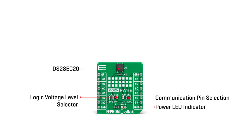
The EEPROM 6 Click Board™ is based on the DS28EC20, a 20Kb of data EEPROM with a fully featured 1-Wire interface in a single chip from Maxim Integrated. The memory is organized as 80 pages of 256 bits each. In addition, the device has one page for control functions such as permanent write protection and EPROM-Emulation mode for individual 2048-bit (8-page) memory blocks. A volatile 256-bit memory page called the scratchpad acts as a buffer when writing data to the EEPROM to ensure data integrity. Data is first written to the scratchpad, from which it can be read back for verification before transferring it to the EEPROM.
Each DS28EC20 has its own unalterable and unique 64-bit registration number. The registration number guarantees unique identification and is used to address the device in a multidrop 1-Wire net environment. In addition to the EEPROM, the device has a 32-byte volatile scratchpad. Writes to the EEPROM array are a two-step process. First, data is written to the scratchpad and then copied into the main array. The user can verify the data in the scratchpad before copying.
The protocol for accessing the DS28EC20 through the 1-Wire interface consists of additional steps:
The EEPROM 6 Click Board™ communicates with MCU using the 1-Wire interface that supports both a Standard and Overdrive communication speed of 15.4kbps (max) and 90kbps (max), respectively. If not explicitly set into the Overdrive mode, the DS28EC20 communicates at Standard speed. The 1-Wire communication line is routed to the SMD jumper labeled as GP SEL, which allows routing of the 1-Wire communication either to the PWM pin or to the AN pin of the mikroBUS™ socket. These pins are labeled as GP0 and GP1 respectively, the same as the SMD jumper positions, making the selection of the desired pin simple and straightforward.
The EEPROM 6 Click Board™ is designed to be operated with both 3.3V and 5V logic voltage levels that can be selected via VCC SEL jumper. This allows for both 3.3V and 5V capable MCUs to use the 1-Wire communication lines properly. However, the Click board™ comes equipped with a library that contains easy to use functions and an example code that can be used as a reference for further development.
| Type | EEPROM |
| Applications | Can be used for applications like device authentication, analog-sensor calibration, ink and toner printer cartridge identification, data for self-configuration of central office switches, wireless base stations, or other modular-based rack systems. |
| On-board modules | The EEPROM 6 Click Board™ is based on the DS28EC20, a 20Kb of data EEPROM with a fully featured 1-Wire interface in a single chip from Maxim Integrated. |
| Key Features | Unique registration number that ensures error-free device selection, switchpoint hysteresis and filtering to optimize performance in the presence of noise, 200k write/erase cycle endurance, and more. |
| Interface | 1-Wire |
| Compatibility | mikroBUS |
| Click board size | S (28.6 x 25.4 mm) |
| Input Voltage | 3.3V or 5V |
This table shows how the pinout on EEPROM 6 Click Board™ corresponds to the pinout on the mikroBUS™ socket (the latter shown in the two middle columns).
| Notes | Pin | Pin | Notes | ||||
|---|---|---|---|---|---|---|---|
| 1-Wire Data IN/OUT | GP1 | 1 | AN | PWM | 16 | GP0 | 1-Wire Data IN/OUT |
| NC | 2 | RST | INT | 15 | NC | ||
| NC | 3 | CS | RX | 14 | NC | ||
| NC | 4 | SCK | TX | 13 | NC | ||
| NC | 5 | MISO | SCL | 12 | NC | ||
| NC | 6 | MOSI | SDA | 11 | NC | ||
| Power Supply | 3.3V | 7 | 3.3V | 5V | 10 | 5V | Power Supply |
| Ground | GND | 8 | GND | GND | 9 | GND | Ground |
| Label | Name | Default | Description |
|---|---|---|---|
| LD1 | PWR | - | Power LED Indicator |
| JP1 | VCC SEL | Right | Power Supply Voltage Selection 3V3/5V: Left position 3V3, Right position 5V |
| JP2 | GP SEL | Right | 1-Wire Data Communication Pin Selection: Left position GP1, Right position GP0 |
| Description | Min | Typ | Max | Unit |
|---|---|---|---|---|
| Supply Voltage | -0.5 | - | 6 | V |
| Memory Size | - | - | 20 | Kb |
| Write/Erase Cycles (Endurance) | 200k | - | - | cycle |
| Operating Temperature Range | -40 | - | +85 | °C |
.
The EEPROM 4 Click is 2,097,152 bits on a Click Board™', organized into 262,144 bytes. In other words, this Click Board™' is an EEPROM memory medium with the capacity of 256 KB. The used EEPROM module has very good endurance and it can withstand 1,000,000 write cycles, with the data retaining period of about 40 years. The EEPROM module on this Click can work with power supply voltage ranging from 1.7V to 5.5V, it features the self-timed write cycles, doesn't require erase before writing, has a dedicated write protect pin for hardware protection of stored data, and has a dedicated hold pin used for holding the data transfer.
EEPROM 4 Click is aimed towards industrial and commercial applications, which require low voltage and low power operational capabilities. It can be used for any kind of temporary or permanent data storage for various embedded electronic devices, simple data logging, storing various working parameters of a module or device, safeguarding the sensitive data in case of a power cycle, and other similar applications where EEPROM memory is needed.
The EEPROM module used on the EEPROM 4 Click is the AT25M02, an SPI serial EEPROM from Microchip, with the memory cell density of 2 Mbits. The EEPROM density is usually expressed in bits, so exactly 2,097,152 bits are organized in units or words of 8 bits, which gives 262,144 bytes of data memory. Furthermore, the EEPROM is organized in so-called pages. One page holds 256 bytes and there are 1024 pages (1024 pages x 256 bytes = 262,144 bytes total). Having insight into how the memory cells are organized, is important for write and erase operations. The SPI pins are routed to the mikroBUS so the communication is easy and straightforward. The SPI can be clocked as high as 5 MHz, providing a fast throughput for the data transfer.
Some other EEPROM memory modules require erasing of the whole memory page before writing new data. This EEPROM doesn't require such operations. It features byte write and page write modes. Before attempting any write operations to the EEPROM, the write enable bit (WEL) of the Status Register needs to be set to 1. This bit is automatically set to 0 after some instructions. There are special instructions used to set and clear the WEN bit of the Status Register. These instructions are WREN (06h) and WRDI (04h). Usually, every write instruction will be prefixed with the WREN instruction.
 .
.
A dedicated #HOLD pin is routed to the PWM pin of the mikroBUS. When the communication with the Click Board™' is initiated by setting the CS pin to a LOW logic state, it is possible to pause the serial data transfer without resetting the communication, if the #HOLD pin (PWM pin on the mikroBUS) is set to a LOW logic state. To resume the communication, it is enough to set this pin to a HIGH logic state while the SCK is still running. Once the HOLD is initiated, the state of the SCK line is irrelevant and any serial data input will be ignored. This pin is pulled HIGH by the on-board resistor.
A dedicated #WP write protect pin is used to put the device into the hardware write protect mode. This pin is routed to the RST pin of the mikroBUS. Hardware write protect works in conjunction with the Write Protect Enable (WPEN) bit of the Status Register. When this bit is set to 1 and the #WP pin is set to a LOW logic state, the device will ignore any attempt to write to the Status Register and the EEPROM memory regions, selected by the Block Write Protect bits of the Status Register (BP0 and BP1). WRSR instruction is used to write to the Status Register (01h). Again, before attempting to write to Status Register, WREN instruction should be executed first. Once the WPEN bit is set to 1 and the RST has been pulled to a LOW logic state, setting the WPEN bit to 0, won't disable write protection, as long as the #WP pin (RST) stays LOW. WPEN bit, as well as the BP0 and BP1 bits, are constructed as EEPROM cells, meaning that they are nonvolatile and will retain their states even after power off. The #WP pin is pulled HIGH by the on-board resistor.
The on-board SMD jumper labelled as VCCSEL is used to select the operating voltage between 3.3V and 5V, as usual. However, there's the third position for this jumper, which is used to set the operating voltage to 1.8V. This is achieved thanks to the TC1015, a small 100 mA LDO from Microchip, which is powered from the 5V rail.
As always, MikroElektronika provides libraries that simplify and speed up working with this device. The provided application example demonstrates the functionality of the provided libraries and can be used as the reference point for own development.
- amazon_main_image: https://www.thedebugstore.com/images/product/lg-eeprom-6-click-front.jpg - amazon_other_image_1: https://www.thedebugstore.com/images/product/lg-eeprom-6-click-back.jpg - amazon_other_image_2: https://www.thedebugstore.com/images/product/lg-eeprom-6-click-fusion.jpg - amazon_other_image_3: https://www.thedebugstore.com/images/product/lg-eeprom-6-click-shuttle.jpg - amazon_other_image_4: https://www.thedebugstore.com/images/product/lg-eeprom-6-click-clicker.jpg - amazon_other_image_5: https://www.thedebugstore.com/images/product/lg-eeprom-6-click-breadboard.jpg - amazon_browse_node: 428655031 - mpn: MIKROE-4296 - backorder_label: If no stock shown above, check availability - badge: - widget:We provide a library for the EEPROM 6 Click Board™ on our LibStock page, as well as a demo application (example), developed using MikroElektronika compilers. The demo can run on all the main MikroElektronika development boards.
The EEPROM 6 Click Board™ utilises the "One_Wire" Library for it's communications and functionalities.
void eeprom6_one_wire_init ( ) - Function initialises one wire communication.void eeprom6_read_mem ( uint16_t reg_adr, uint16_t n_len ) - The Read Memory function allows data to be sequentially read starting at an initial address.uint8_t eeprom6_write_mem ( uint16_t reg_adr, uint16_t n_len ) - The Write Memory function allows data bytes to be written sequentially.The application is composed of three sections :
void application_task ( )
{
 mikrobus_logWrite( "Writing : ", _LOG_TEXT );
 mikrobus_logWrite( val_in, _LOG_TEXT );
 eeprom6_write_mem( 0x0000, 9 );
 Delay_ms( 100 );
 mikrobus_logWrite( "Reading : ", _LOG_TEXT );
 eeprom6_read_mem ( 0x0000, 9 );
 mikrobus_logWrite( val_out, _LOG_TEXT );
 mikrobus_logWrite( "-------------------", _LOG_LINE );
 Delay_ms( 5000 );
}
The full application code, and ready to use projects can be found on our LibStock page.
Other mikroE Libraries used in the example:
The full application code, and ready to use projects can be found on our LibStock page.
Other mikroE Libraries used in the example:
Depending on the development board you are using, you may need a USB UART click, USB UART 2 click or RS232 click to connect to your PC, for development systems with no UART to USB interface available on the board. The terminal available in all MikroElektronika compilers, or any other terminal application of your choice, can be used to read the message.
The EEPROM 6 Click Board™ is supported with mikroSDK - MikroElektronika Software Development Kit. To ensure proper operation of mikroSDK compliant Click board™ demo applications, mikroSDK should be downloaded from the LibStock and installed for the compiler you are using.
- attachments: [{"download_file":[{"download_file":"EEPROM 6 Click Board™ Schematic"}],"download_filetype":[{"download_filetype":"pdf"}]},{"download_file":[{"download_file":"Maxim DS28EC20 20480-Bit EEPROM Datasheet"}],"download_filetype":[{"download_filetype":"pdf"}]}] - condition: new - custom_product: false - mpn: MIKROE-4296 - google_product_category: Electronics - custom_label_0: Click Board - device_vendor: Maxim Integrated - device_type: DS28EC20P+T - warranty: 12 months - brand: MikroE - manufacturer: Mikroelektronika d.o.o. - target_keyword: EEPROM 6 Click Board - brands: gid://shopify/Metaobject/56256004319 - breadcrumbs: ["gid://shopify/Collection/447955239135","gid://shopify/Collection/241680580797","gid://shopify/Collection/241545183421"] - customhs_code: 847330 - detailed_description: {"type":"root","children":[{"type":"heading","level":3,"children":[{"type":"text","value":"Hoes Does The EEPROM 6 Click Board™ Work?"}]},{"type":"paragraph","children":[{"type":"text","value":"The"},{"type":"text","value":" EEPROM 6 Click Board™","bold":true,"italic":true},{"type":"text","value":" is based on the DS28EC20, a 20Kb of data EEPROM with a fully featured 1-Wire interface in a single chip from Maxim Integrated. The memory is organized as 80 pages of 256 bits each. In addition, the device has one page for control functions such as permanent write protection and EPROM-Emulation mode for individual 2048-bit (8-page) memory blocks. A volatile 256-bit memory page called the scratchpad acts as a buffer when writing data to the EEPROM to ensure data integrity. Data is first written to the scratchpad, from which it can be read back for verification before transferring it to the EEPROM."}]},{"type":"paragraph","children":[{"type":"text","value":""}]},{"type":"paragraph","children":[{"type":"text","value":" "}]},{"type":"paragraph","children":[{"type":"text","value":"Each DS28EC20 has its own unalterable and unique 64-bit registration number. The registration number guarantees unique identification and is used to address the device in a multidrop 1-Wire net environment. In addition to the EEPROM, the device has a 32-byte volatile scratchpad. Writes to the EEPROM array are a two-step process. First, data is written to the scratchpad and then copied into the main array. The user can verify the data in the scratchpad before copying."}]},{"type":"paragraph","children":[{"type":"text","value":"The protocol for accessing the DS28EC20 through the 1-Wire interface consists of additional steps:"}]},{"type":"list","listType":"unordered","children":[{"type":"list-item","children":[{"type":"text","value":"Initialization sequence","bold":true},{"type":"text","value":" - It consists of a reset pulse transmitted by the MCU followed by the presence pulse transmitted by the DS28EC20, which gives the MCU information that the DS28EC20 is on the bus and is ready to operate."}]},{"type":"list-item","children":[{"type":"text","value":"ROM Function Command","bold":true},{"type":"text","value":" - Once the MCU has detected a presence, it can issue one of the seven ROM function commands that the DS28EC20 support."}]},{"type":"list-item","children":[{"type":"text","value":"Memory Function Command","bold":true},{"type":"text","value":" - Commands necessary for accessing the memory of the DS28EC20."}]},{"type":"list-item","children":[{"type":"text","value":"Transaction/Data","bold":true},{"type":"text","value":" - The idle state for the 1-Wire bus is high. If for any reason a transaction needs to be suspended, the bus MUST be left in the idle state if the transaction is to resume. If this does not occur and the bus is left low for more than 16μs (Overdrive speed) or more than 120μs (Standard speed), one or more devices on the bus can be reset."}]}]},{"type":"paragraph","children":[{"type":"text","value":"The"},{"type":"text","value":" EEPROM 6 Click Board™","bold":true},{"type":"text","value":" communicates with MCU using the 1-Wire interface that supports both a Standard and Overdrive communication speed of 15.4kbps (max) and 90kbps (max), respectively. If not explicitly set into the Overdrive mode, the DS28EC20 communicates at Standard speed. The 1-Wire communication line is routed to the SMD jumper labeled as GP SEL, which allows routing of the 1-Wire communication either to the PWM pin or to the AN pin of the mikroBUS™ socket. These pins are labeled as GP0 and GP1 respectively, the same as the SMD jumper positions, making the selection of the desired pin simple and straightforward."}]},{"type":"paragraph","children":[{"type":"text","value":"The "},{"type":"text","value":"EEPROM 6 Click Board™","bold":true},{"type":"text","value":" is designed to be operated with both 3.3V and 5V logic voltage levels that can be selected via VCC SEL jumper. This allows for both 3.3V and 5V capable MCUs to use the 1-Wire communication lines properly. However, the Click board™ comes equipped with a library that contains easy to use functions and an example code that can be used as a reference for further development."}]},{"type":"heading","level":3,"children":[{"type":"text","value":"SPECIFICATIONS"}]},{"type":"paragraph","children":[{"type":"text","value":"Type\nEEPROM\nApplications\nCan be used for applications like device authentication, analog-sensor calibration, ink and toner printer cartridge identification, data for self-configuration of central office switches, wireless base stations, or other modular-based rack systems.\nOn-board modules\nThe EEPROM 6 Click Board™ is based on the DS28EC20, a 20Kb of data EEPROM with a fully featured 1-Wire interface in a single chip from Maxim Integrated.\nKey Features\nUnique registration number that ensures error-free device selection, switchpoint hysteresis and filtering to optimize performance in the presence of noise, 200k write/erase cycle endurance, and more.\nInterface\n1-Wire\nCompatibility\nmikroBUS\nClick board size\nS (28.6 x 25.4 mm)\nInput Voltage\n3.3V or 5V"}]},{"type":"heading","level":3,"children":[{"type":"text","value":"PINOUT DIAGRAM"}]},{"type":"paragraph","children":[{"type":"text","value":"This table shows how the pinout on "},{"type":"text","value":"EEPROM 6 Click Board™","bold":true},{"type":"text","value":" corresponds to the pinout on the mikroBUS™ socket (the latter shown in the two middle columns)."}]},{"type":"paragraph","children":[{"type":"text","value":"Notes\nPin\nPin\nNotes\n1-Wire Data IN/OUT\nGP1\n1\nAN\nPWM\n16\nGP0\n1-Wire Data IN/OUT\nNC\n2\nRST\nINT\n15\nNC\nNC\n3\nCS\nRX\n14\nNC\nNC\n4\nSCK\nTX\n13\nNC\nNC\n5\nMISO\nSCL\n12\nNC\nNC\n6\nMOSI\nSDA\n11\nNC\nPower Supply\n3.3V\n7\n3.3V\n5V\n10\n5V\nPower Supply\nGround\nGND\n8\nGND\nGND\n9\nGND\nGround"}]},{"type":"heading","level":3,"children":[{"type":"text","value":"ONBOARD SETTINGS AND INDICATORS"}]},{"type":"paragraph","children":[{"type":"text","value":"Label\nName\nDefault\n Description\nLD1\nPWR\n-\nPower LED Indicator\nJP1\nVCC SEL\nRight\nPower Supply Voltage Selection 3V3/5V: Left position 3V3, Right position 5V\nJP2\nGP SEL\nRight\n1-Wire Data Communication Pin Selection: Left position GP1, Right position GP0"}]},{"type":"heading","level":3,"children":[{"type":"text","value":"EEPROM 6 CLICK ELECTRICAL SPECIFICATIONS"}]},{"type":"paragraph","children":[{"type":"text","value":"Description\nMin\nTyp\nMax\nUnit\nSupply Voltage\n-0.5\n-\n6\nV\nMemory Size\n-\n-\n20\nKb\nWrite/Erase Cycles (Endurance)\n200k\n-\n-\ncycle\nOperating Temperature Range\n-40\n-\n+85\n°C"}]},{"type":"heading","level":3,"children":[{"type":"text","value":" "}]}]} - summary:The EEPROM 6 Click Board™ is a compact add-on board that contains a serial EEPROM memory that operates from the 1-Wire interface. This board features the DS28EC20, a 20480-bit EEPROM organized as 80 memory pages of 256 bits each from Maxim Integrated. As a specific feature, blocks of eight memory pages can be write-protected or put in the “EPROM-Emulation” Mode, where bits can only be changed from a 1 to a 0 state. It communicates with MCU at 15.4kbps or 90kbps over the 1-Wire protocol and has a 64-bit registration number that ensures error-free device selection. This Click Board™ is suitable for applications like device authentication, data for self-configuration of central office switches, wireless base stations, or other modular-based rack systems.
The EEPROM 6 Click Board™ is supported by a mikroSDK compliant library, which includes functions that simplify software development. This Click Board™ comes as a fully tested product, ready to be used on a system equipped with the mikroBUS™ socket.