# Title: RTD 2 Click Board™
## Description: How Does The RTD 2 Click Board™ Work? The RTD 2 Click Board™ is based on the ADS1247, a highly integrated 24-bit data converters with a programmable gain amplifier (PGA) for sensor measurement applications from Texas Instruments. The ADS1247 includes a delta-sigma (ΔΣ) ADC with an adjustable single-cycle settling digital filter, an internal oscillator, and an SPI-compatible serial interface. It also has a flexible input multiplexer with system monitoring capability and general-purpose I/O settings, a very low-drift voltage reference, and two matched current sources for sensor excitation. The ADS1247 provides a system monitor function. This function can measure the analog power supply, digital power supply, external voltage reference, or ambient temperature. Note that the system monitor function provides a coarse result. When the system monitor is enabled, the analog inputs are disconnected. The two IDAC current sources integrated in the ADS1247 are used to implement the lead-wire compensation. One IDAC current source (IDAC1) provides excitation to the RTD element. The other current source (IDAC2) has the same current setting, providing cancellation of lead-wire resistance by generating a voltage drop across lead-wire resistance R2 equal to the voltage drop across R1 resistor (9.09k). Because the voltage across the RTD is measured differentially at ADC pins AIN1 and AIN2 of the ADS1247, the voltages across the lead-wire resistances cancel. The ADC reference voltage (pins REFP0 and REFN0) is derived from the voltage across R5 resistor with the currents from IDAC1 and IDAC2, providing ratiometric cancellation of current-source drift. R5 also level shifts the RTD signal to within the ADC specified common-mode input range. The RTD 2 Click Board™ communicates with MCU using the standard SPI serial interface with additional data ready signal routed on the INT pin of the mikroBUS™ socket labelled as RDY. Data Ready signal is used to indicate when a new conversion is complete, and the conversion result is stored in the conversion result buffer. It also has an active-low Reset signal routed on the RST pin of the mikroBUS™ used to reset the device, and precise conversion control signal routed on the AN pin of the mikroBUS™ socket labelled as STR. The ADS1247 stays in Reset Mode as long as the RST pin stays low. When the RST pin goes high, the ADC comes out of Reset Mode and can convert data. The RTD 2 Click Board™ can work only with 3-wire probe types that MikroE has in its offer such as the PT100 type Platinum Probe, a type of RTD probe used to measure temperatures up to 250°C. Platinum is an excellent choice since they are very stable and reusable, and are resistant to corrosion or oxidation. The measurement probe is connected to the RTD 2 Click by using the screw terminal on the top of the board, and it has wires that can be 1m long, which makes it possible to measure high temperatures from a safe distance. The RTD 2 Click Board™ is designed to be operated only with a 3.3V logic voltage level. A proper logic voltage level conversion should be performed before the Click board™ is used with MCUs with different logic levels. However, the Click board™ comes equipped with a library that contains easy to use functions and an example code that can be used as a reference for further development. SPECIFICATIONS Type Temperature & humidity Applications Can be used for temperature sensor measurements such as RTDs, thermocouples, and thermistors, for pressure measurements, flow meters, factory automation, and process control, and many more. On-board modules The RTD 2 Click Board™ is based on the ADS1247, a highly integrated 24-bit data converters with a programmable gain amplifier (PGA) for sensor measurement applications from Texas Instruments. Key Features Programmable Data Rates, 50/60 Hz rejection, excitation current sources (iDACs), GPIO, PGA, internal temperature sensor, self and system calibration, and more. Interface SPI Compatibility mikroBUS Click board size M (42.9 x 25.4 mm) Input Voltage 3.3V PINOUT DIAGRAM This table shows how the pinout of the RTD 2 Click Board™ corresponds to the pinout on the mikroBUS™ socket (the latter shown in the two middle columns). Notes Pin Pin Notes Conversion Start STR 1 AN PWM 16 NC Reset RST 2 RST INT 15 RDY Data-Ready SPI Chip Select CS 3 CS RX 14 NC SPI Clock SCK 4 SCK TX 13 NC SPI Data OUT SDO 5 MISO SCL 12 NC SPI Data IN SDI 6 MOSI SDA 11 NC Power Supply 3.3V 7 3.3V 5V 10 NC Ground GND 8 GND GND 9 GND Ground ONBOARD SETTINGS AND INDICATORS Label Name Default Description LD1 PWR - Power LED Indicator RTD 2 CLICK ELECTRICAL SPECIFICATIONS Description Min Typ Max Unit Supply Voltage -0.3 3.3 5.5 V Power Consumption - 2.3 - mW Sample Rate - - 2 kSPS Resolution - 24 - bit Operating Temperature Range -40 - +105 °C
## Product type: Click Board
## Vendor: Mikroelektronika d.o.o.
## Tags: Click Board, MikroE, Sensor, Temp&Hum, Temperature
## Price range: 20.3 - 20.3 GBP
## Link: https://thedebugstore.com/products/mikroe-4282-rtd-2-click-board-uk
## Compare-at price range: 29.0 - 29.0 GBP
## Options
- Title: Default Title
## Collections
- [New Products](https://thedebugstore.com/a/llms/collections/new-products-debug-store)
- [Mikroelektronika d.o.o. (MikroE)](https://thedebugstore.com/a/llms/collections/mikroelektronika-catalogue-uk)
- [Sensor Click Boards™](https://thedebugstore.com/a/llms/collections/sensor-click-boards-catalogue)
- [MikroE Click Boards™](https://thedebugstore.com/a/llms/collections/mikroe-click-boards-catalogue-uk)
- [Temperature Sensor Click Boards™](https://thedebugstore.com/a/llms/collections/temperature-sensor-click-boards-catalogue)
- [Click Boards™ Summer Sale](https://thedebugstore.com/a/llms/collections/inventory-sale)
- [MikroE Sale](https://thedebugstore.com/a/llms/collections/mikroe-sale)
- [MIKROE Stock](https://thedebugstore.com/a/llms/collections/mikroe-products-in-stock-sale)
## Variants
- Default Title, SKU: MIKROE-4282, Available: yes, Inventory: 1
## Metafields
- full_description: How Does The RTD 2 Click Board™ Work?
The RTD 2 Click Board™ is based on the ADS1247, a highly integrated 24-bit data converters with a programmable gain amplifier (PGA) for sensor measurement applications from Texas Instruments. The ADS1247 includes a delta-sigma (ΔΣ) ADC with an adjustable single-cycle settling digital filter, an internal oscillator, and an SPI-compatible serial interface. It also has a flexible input multiplexer with system monitoring capability and general-purpose I/O settings, a very low-drift voltage reference, and two matched current sources for sensor excitation. The ADS1247 provides a system monitor function. This function can measure the analog power supply, digital power supply, external voltage reference, or ambient temperature. Note that the system monitor function provides a coarse result. When the system monitor is enabled, the analog inputs are disconnected.
The two IDAC current sources integrated in the ADS1247 are used to implement the lead-wire compensation. One IDAC current source (IDAC1) provides excitation to the RTD element. The other current source (IDAC2) has the same current setting, providing cancellation of lead-wire resistance by generating a voltage drop across lead-wire resistance R2 equal to the voltage drop across R1 resistor (9.09k). Because the voltage across the RTD is measured differentially at ADC pins AIN1 and AIN2 of the ADS1247, the voltages across the lead-wire resistances cancel. The ADC reference voltage (pins REFP0 and REFN0) is derived from the voltage across R5 resistor with the currents from IDAC1 and IDAC2, providing ratiometric cancellation of current-source drift. R5 also level shifts the RTD signal to within the ADC specified common-mode input range.
The RTD 2 Click Board™ communicates with MCU using the standard SPI serial interface with additional data ready signal routed on the INT pin of the mikroBUS™ socket labelled as RDY. Data Ready signal is used to indicate when a new conversion is complete, and the conversion result is stored in the conversion result buffer. It also has an active-low Reset signal routed on the RST pin of the mikroBUS™ used to reset the device, and precise conversion control signal routed on the AN pin of the mikroBUS™ socket labelled as STR. The ADS1247 stays in Reset Mode as long as the RST pin stays low. When the RST pin goes high, the ADC comes out of Reset Mode and can convert data.
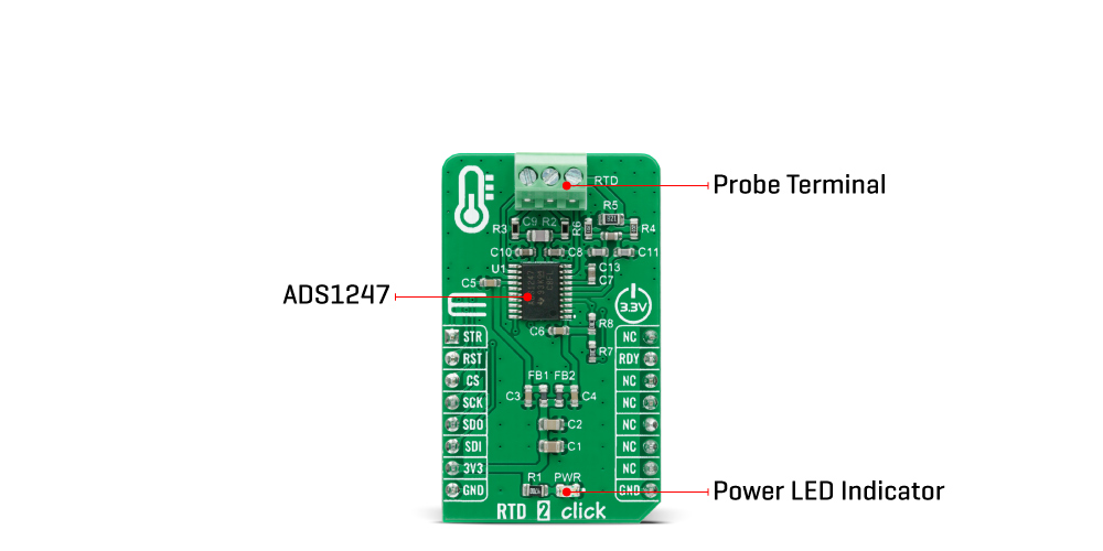
The RTD 2 Click Board™ can work only with 3-wire probe types that MikroE has in its offer such as the PT100 type Platinum Probe, a type of RTD probe used to measure temperatures up to 250°C. Platinum is an excellent choice since they are very stable and reusable, and are resistant to corrosion or oxidation. The measurement probe is connected to the RTD 2 Click by using the screw terminal on the top of the board, and it has wires that can be 1m long, which makes it possible to measure high temperatures from a safe distance.
The RTD 2 Click Board™ is designed to be operated only with a 3.3V logic voltage level. A proper logic voltage level conversion should be performed before the Click board™ is used with MCUs with different logic levels. However, the Click board™ comes equipped with a library that contains easy to use functions and an example code that can be used as a reference for further development.
SPECIFICATIONS
| Type |
Temperature & humidity |
| Applications |
Can be used for temperature sensor measurements such as RTDs, thermocouples, and thermistors, for pressure measurements, flow meters, factory automation, and process control, and many more. |
| On-board modules |
The RTD 2 Click Board™ is based on the ADS1247, a highly integrated 24-bit data converters with a programmable gain amplifier (PGA) for sensor measurement applications from Texas Instruments. |
| Key Features |
Programmable Data Rates, 50/60 Hz rejection, excitation current sources (iDACs), GPIO, PGA, internal temperature sensor, self and system calibration, and more. |
| Interface |
SPI |
| Compatibility |
mikroBUS |
| Click board size |
M (42.9 x 25.4 mm) |
| Input Voltage |
3.3V |
PINOUT DIAGRAM
This table shows how the pinout of the RTD 2 Click Board™ corresponds to the pinout on the mikroBUS™ socket (the latter shown in the two middle columns).
| Notes |
Pin |
 |
Pin |
Notes |
| Conversion Start |
STR |
1 |
AN |
PWM |
16 |
NC |
| Reset |
RST |
2 |
RST |
INT |
15 |
RDY |
Data-Ready |
| SPI Chip Select |
CS |
3 |
CS |
RX |
14 |
NC |
| SPI Clock |
SCK |
4 |
SCK |
TX |
13 |
NC |
| SPI Data OUT |
SDO |
5 |
MISO |
SCL |
12 |
NC |
| SPI Data IN |
SDI |
6 |
MOSI |
SDA |
11 |
NC |
| Power Supply |
3.3V |
7 |
3.3V |
5V |
10 |
NC |
| Ground |
GND |
8 |
GND |
GND |
9 |
GND |
Ground |
ONBOARD SETTINGS AND INDICATORS
| Label |
Name |
Default |
Description |
| LD1 |
PWR |
- |
Power LED Indicator |
RTD 2 CLICK ELECTRICAL SPECIFICATIONS
| Description |
Min |
Typ |
Max |
Unit |
| Supply Voltage |
-0.3 |
3.3 |
5.5 |
V |
| Power Consumption |
- |
2.3 |
- |
mW |
| Sample Rate |
- |
- |
2 |
kSPS |
| Resolution |
- |
24 |
- |
bit |
| Operating Temperature Range |
-40 |
- |
+105 |
°C |
- description_tag: The RTD 2 Click Board™ is a compact add-on board used for applications with resistive elements that change resistance over temperature. This board features the ADS1247, 24-bit ADC with a programmable gain amplifier (PGA) for sensor measurement applications from Texas Instruments. Available from Debug Store UK.
- title_tag: MikroE RTD 2 Click Board™ (MIKROE-4282)
- manufacturer: Mikroelektronika d.o.o.
- warranty: 12 months
- amazon_enable: TRUE
- amazon_title: RTD 2 Click Board
- amazon_product_type: computercomponent
- amazon_block: FALSE
- amazon_prime_enable: FALSE
- amazon_search: MikroElektronika Microelectronica MIKROE-1100
- amazon_uk_price: 26.4
- amazon_uk_currency: GBP
- amazon_de_currency: EUR
- amazon_de_price: 29.832
- amazon_fr_currency: EUR
- amazon_fr_price: 29.832
- amazon_es_currency: EUR
- amazon_es_price: 29.832
- amazon_nl_currency: EUR
- amazon_nl_price: 29.832
- amazon_it_currency: EUR
- amazon_it_price: 29.832
- amazon_se_curency: SEK
- amazon_se_price: 300.96
- amazon_product_id: 8606018711888
- amazon_product_id_type: EAN
- amazon_update: Update
- amazon_short_description: The RTD 2 Click Board™ is a compact add-on board used for applications with resistive elements that change resistance over temperature. This board features the ADS1247, 24-bit analog-to-digital converter with a programmable gain amplifier (PGA) for sensor measurement applications from Texas Instruments. It features a precision delta-sigma (ΔΣ) ADC with a single-cycle settling digital filter, and an internal oscillator, but also provides a low-drift voltage reference, and two matched programmable excitation current sources (IDACs). It also integrates sensor burn-out detection, voltage bias for thermocouples, system monitoring, and digital GPIOs. This Click board™ is suitable for temperature sensor measurements such as RTDs, thermocouples and thermistors, for pressure measurements, process control, and many more.RTD 2 Click is supported by a mikroSDK compliant library, which includes functions that simplify software development. This Click board™ comes as a fully tested product, ready to be used on a system equipped with the mikroBUS™ socket.
- amazon_long_description: The RTD Click is based on MAX31865 resistance to digital converter from Maxim Integrated, optimized for platinum resistance temperature detectors, or RTD. The Click uses the PT100 type platinum probefor temperature measurement. There are four screw terminals on the board, so different PT100 probe types can be used with this design. This Click Board™' can work with 2, 3 or 4-wire PT100 probe types.
RTD probes are commonly used to measure a range of temperatures between -200°C and 500°C, but the exact value depends on the specific probes used. Features like the 15bit ADC resolution, input terminals over-voltage protection up to ±45V, fault detection, fast response time of 21mS and the SPI interface, make the RTD Click an ideal solution when it comes to precise measuring of extremely high and low temperatures.
How the Click Board™ works
RTD sensors are basically thermosensitive resistors materials that change the resistance depending on their temperature. In this case, the resistor is a small strip of platinum with a resistance of 100Ωat 0°C - that is why it is called PT100. The RTD measurement is more stable and precise than with most NTC/PTC thermistors, so it is commonly used for measuring temperature in the laboratory and industrial processes.
Measurement probe is connected to the RTD Click by using the screw terminals, and it has wires that can be 1m long, which makes possible to measure high temperatures from a safe distance. To successfully measure small differences in the sensor resistance, the signal must be amplified. There is an input signal amplifier before the ADC converter, inside the MAX 31865 IC. Once amplified, the signal goes through the ADC converter and then, this value can be then read through the SPI interface on the mikroBUS socket. Since the temperature vs resistance curve of the platinum probes is not ideal, a compensating calculation is done with the functions, contained in the Click library. The 15bit ADC can provide the resolution of ±0.3125°C, but the total accuracy of the RTD Click is ±0.5°C.
The RTD Click can work with several different variations of the RTD probes:.
- The 2-wire probe connection can give acceptable results when the RTD is located close to the MAX31865. For the PT100 probes, the series resistance of 0.4Ω causes an error of approximately 1°C. Therefore, as the cable length increases, the error due to cable resistance can become excessive.
- The 3-wire probe connection is a compromise that uses one less conductor than the 4-wire solution. If the cable resistances are well matched, the error due to cable resistance is cancelled.
- The 4-wire probe connection eliminates errors due to cable resistance by using separate force and sense leads.
To select proper mode for the type of the connected probe, the SMD jumpers on the Click Board™ must be set to a proper position. The jumper settings can be found in the on-board settings and indicators table, below.DRDY - Data ready pin is used to signal a ready status to the MCU. This pin will go to a LOW logic state when there is a new conversion result is available in the data register. When a read operation of an RTD resistance data register occurs, DRDY goes to a HIGH logic level. It can be used to trigger an interrupt on the MCU so that the polling of the temperature registers can be avoided.
- amazon_main_image: https://www.thedebugstore.com/images/product/lg-rtd-2-click-front.jpg
- amazon_other_image_1: https://www.thedebugstore.com/images/product/lg-rtd-2-click-back.jpg
- amazon_other_image_2: https://www.thedebugstore.com/images/product/lg-rtd-2-click-fusion.jpg
- amazon_other_image_3: https://www.thedebugstore.com/images/product/lg-rtd-2-click-shuttle.jpg
- amazon_other_image_4: https://www.thedebugstore.com/images/product/lg-rtd-2-click-clicker.jpg
- amazon_other_image_5: https://www.thedebugstore.com/images/product/lg-rtd-2-click-breadboard.jpg
- amazon_other_image_6: https://www.thedebugstore.com/images/product/lg-rtd-2-click-breadboard.jpg
- amazon_browse_node: 428655031
- mpn: MIKROE-4282
- backorder_label: If no stock shown above, check availability
- condition: new
- custom_product: false
- mpn: MIKROE-4282
- google_product_category: Electronics
- custom_label_0: Click Board
- examples:
We provide a library for the RTD 2 Click Board™ on our LibStock page, as well as a demo application (example), developed using MikroElektronika compilers. The demo can run on all the main MikroElektronika development boards.
Library Description
The library covers all the necessary functions to control the RTD 2 Click Board™. A library performs the communication with the 4ADS1247 24-Bit, 2-kSPS, Analog-To-Digital Converters With Programmable Gain Amplifier (PGA) For Sensor Measurement via I2C interface.
Key Functions
void rtd2_hw_reset ( void ) - Hardware reset function.void rtd2_default_config ( void ) - Set default configuration function.float rtd2_get_temperature ( void ) - Get temperature function.
Example Description
The application is composed of three sections :
- System Initialization - Initializes SPI, sets AN, RST and CS pins as output, INT pin as input and start to write log.
- Application Initialization - Initialization driver enables - SPI, hardware reset the device and set default configuration and start the measurement, also write log.
- Application Task - (code snippet) This is an example that demonstrates the use of the RTD 2 Click Board™ . RTD 2 Click board can be used to measure ambient temperature from the PT100 3-wire temperature probe wired to the 4ADS1247 24-Bit, 2-kSPS, Analog-To-Digital Converters With Programmable Gain Amplifier (PGA) For Sensor Measurement on the RTD 2 Click Board™. All data logs write on USB UART changes for every 1 sec.
void application_task ( )
{
    if ( rtd2_check_new_data_ready( ) == RTD2_NEW_DATA_IS_READY )
    {
        temperature = rtd2_get_temperature( );
        FloatToStr( temperature, log_text );
        mikrobus_logWrite( " Temperature : ", _LOG_TEXT );
        mikrobus_logWrite( log_text, _LOG_TEXT );
        mikrobus_logWrite( " C", _LOG_LINE );
        mikrobus_logWrite( "--------------------------", _LOG_LINE );
        Delay_ms( 1000 );
    }
    else
    {
        rtd2_enable_start( RTD2_START_CONVERSION_DISABLE );
        Delay_ms( 1000 );
    }
}
The full application code, and ready to use projects can be found on our LibStock page.
Other mikroE Libraries used in the example:
Additional Notes and Information
Depending on the development board you are using, you may need USB UART Click Board™, USB UART 2 Click Board™ or RS232 Click Board™ to connect to your PC, for development systems with no UART to USB interface available on the board. The terminal available in all MikroElektronika compilers, or any other terminal application of your choice, can be used to read the message.
MIKROSDK
Te RTD 2 Click Board™ is supported with mikroSDK - MikroElektronika Software Development Kit. To ensure proper operation of mikroSDK compliant Click board™ demo applications, mikroSDK should be downloaded from the LibStock and installed for the compiler you are using.
- attachments: [{"download_file":[{"download_file":"RTD 2 Click Board™ Schematic"}],"download_filetype":[{"download_filetype":"pdf"}]},{"download_file":[{"download_file":"Texas Instruments ADS1247 24-Bit ADC and PGA Datasheet"}],"download_filetype":[{"download_filetype":"pdf"}]}]
- device_vendor: Texas Instruments
- device_type: ADS1247IPWR
- warranty: 12 months
- brand: MikroE
- key_feature_1: For Sensitive Temperature Measurement
- manufacturer: Mikroelektronika d.o.o.
- badge: No reviews
- widget:
- target_keyword: RTD 2 Click Board
- brands: gid://shopify/Metaobject/56256004319
- breadcrumbs: ["gid://shopify/Collection/447955239135","gid://shopify/Collection/241680580797","gid://shopify/Collection/241545969853"]
- customhs_code: 847330
- detailed_description: {"type":"root","children":[{"type":"heading","level":3,"children":[{"type":"text","value":"How Does The RTD 2 Click Board™ Work?"}]},{"type":"paragraph","children":[{"type":"text","value":"The "},{"type":"text","value":"RTD 2 Click Board™","bold":true,"italic":true},{"type":"text","value":" ","italic":true},{"type":"text","value":"is based on the ADS1247, a highly integrated 24-bit data converters with a programmable gain amplifier (PGA) for sensor measurement applications from Texas Instruments. The ADS1247 includes a delta-sigma (ΔΣ) ADC with an adjustable single-cycle settling digital filter, an internal oscillator, and an SPI-compatible serial interface. It also has a flexible input multiplexer with system monitoring capability and general-purpose I/O settings, a very low-drift voltage reference, and two matched current sources for sensor excitation. The ADS1247 provides a system monitor function. This function can measure the analog power supply, digital power supply, external voltage reference, or ambient temperature. Note that the system monitor function provides a coarse result. When the system monitor is enabled, the analog inputs are disconnected."}]},{"type":"paragraph","children":[{"type":"text","value":""}]},{"type":"paragraph","children":[{"type":"text","value":"The two IDAC current sources integrated in the ADS1247 are used to implement the lead-wire compensation. One IDAC current source (IDAC1) provides excitation to the RTD element. The other current source (IDAC2) has the same current setting, providing cancellation of lead-wire resistance by generating a voltage drop across lead-wire resistance R2 equal to the voltage drop across R1 resistor (9.09k). Because the voltage across the RTD is measured differentially at ADC pins AIN1 and AIN2 of the ADS1247, the voltages across the lead-wire resistances cancel. The ADC reference voltage (pins REFP0 and REFN0) is derived from the voltage across R5 resistor with the currents from IDAC1 and IDAC2, providing ratiometric cancellation of current-source drift. R5 also level shifts the RTD signal to within the ADC specified common-mode input range."}]},{"type":"paragraph","children":[{"type":"text","value":"The "},{"type":"text","value":"RTD 2 Click Board™","bold":true},{"type":"text","value":" communicates with MCU using the standard SPI serial interface with additional data ready signal routed on the INT pin of the mikroBUS™ socket labelled as RDY. Data Ready signal is used to indicate when a new conversion is complete, and the conversion result is stored in the conversion result buffer. It also has an active-low Reset signal routed on the RST pin of the mikroBUS™ used to reset the device, and precise conversion control signal routed on the AN pin of the mikroBUS™ socket labelled as STR. The ADS1247 stays in Reset Mode as long as the RST pin stays low. When the RST pin goes high, the ADC comes out of Reset Mode and can convert data."}]},{"type":"paragraph","children":[{"type":"text","value":"The "},{"type":"text","value":"RTD 2 Click Board™","bold":true},{"type":"text","value":" can work only with 3-wire probe types that MikroE has in its offer such as the PT100 type Platinum Probe, a type of RTD probe used to measure temperatures up to 250°C. Platinum is an excellent choice since they are very stable and reusable, and are resistant to corrosion or oxidation. The measurement probe is connected to the RTD 2 Click by using the screw terminal on the top of the board, and it has wires that can be 1m long, which makes it possible to measure high temperatures from a safe distance."}]},{"type":"paragraph","children":[{"type":"text","value":"The "},{"type":"text","value":"RTD 2 Click Board™","bold":true},{"type":"text","value":" is designed to be operated only with a 3.3V logic voltage level. A proper logic voltage level conversion should be performed before the Click board™ is used with MCUs with different logic levels. However, the Click board™ comes equipped with a library that contains easy to use functions and an example code that can be used as a reference for further development."}]},{"type":"heading","level":3,"children":[{"type":"text","value":"SPECIFICATIONS"}]},{"type":"paragraph","children":[{"type":"text","value":"Type\nTemperature & humidity\nApplications\nCan be used for temperature sensor measurements such as RTDs, thermocouples, and thermistors, for pressure measurements, flow meters, factory automation, and process control, and many more.\nOn-board modules\nThe RTD 2 Click Board™ is based on the ADS1247, a highly integrated 24-bit data converters with a programmable gain amplifier (PGA) for sensor measurement applications from Texas Instruments.\nKey Features\nProgrammable Data Rates, 50/60 Hz rejection, excitation current sources (iDACs), GPIO, PGA, internal temperature sensor, self and system calibration, and more.\nInterface\nSPI\nCompatibility\nmikroBUS\nClick board size\nM (42.9 x 25.4 mm)\nInput Voltage\n3.3V"}]},{"type":"heading","level":3,"children":[{"type":"text","value":"PINOUT DIAGRAM"}]},{"type":"paragraph","children":[{"type":"text","value":"This table shows how the pinout of the "},{"type":"text","value":"RTD 2 Click Board™","bold":true},{"type":"text","value":" corresponds to the pinout on the mikroBUS™ socket (the latter shown in the two middle columns)."}]},{"type":"paragraph","children":[{"type":"text","value":"Notes\nPin\nPin\nNotes\nConversion Start\nSTR\n1\nAN\nPWM\n16\nNC\nReset\nRST\n2\nRST\nINT\n15\nRDY\nData-Ready\nSPI Chip Select\nCS\n3\nCS\nRX\n14\nNC\nSPI Clock\nSCK\n4\nSCK\nTX\n13\nNC\nSPI Data OUT\nSDO\n5\nMISO\nSCL\n12\nNC\nSPI Data IN\nSDI\n6\nMOSI\nSDA\n11\nNC\nPower Supply\n3.3V\n7\n3.3V\n5V\n10\nNC\nGround\nGND\n8\nGND\nGND\n9\nGND\nGround"}]},{"type":"heading","level":3,"children":[{"type":"text","value":"ONBOARD SETTINGS AND INDICATORS"}]},{"type":"paragraph","children":[{"type":"text","value":"Label\nName\nDefault\nDescription\nLD1\nPWR\n-\nPower LED Indicator"}]},{"type":"heading","level":3,"children":[{"type":"text","value":"RTD 2 CLICK ELECTRICAL SPECIFICATIONS"}]},{"type":"paragraph","children":[{"type":"text","value":"Description\nMin\nTyp\nMax\nUnit\nSupply Voltage\n-0.3\n3.3\n5.5\nV\nPower Consumption\n-\n2.3\n-\nmW\nSample Rate\n-\n-\n2\nkSPS\nResolution\n-\n24\n-\nbit\nOperating Temperature Range\n-40\n-\n+105\n°C"}]},{"type":"heading","level":3,"children":[{"type":"text","value":" "}]}]}
- summary: The RTD 2 Click Board™ is a compact add-on board used for applications with resistive elements that change resistance over temperature. This board features the ADS1247, 24-bit analogue-to-digital converter with a programmable gain amplifier (PGA) for sensor measurement applications from Texas Instruments. It features a precision delta-sigma (ΔΣ) ADC with a single-cycle settling digital filter, and an internal oscillator, but also provides a low-drift voltage reference, and two matched programmable excitation current sources (IDACs). It also integrates sensor burn-out detection, voltage bias for thermocouples, system monitoring, and digital GPIOs. This Click Board™ is suitable for temperature sensor measurements such as RTDs, thermocouples and thermistors, for pressure measurements, process control, and many more.
The RTD 2 Click Board™ is supported by a mikroSDK compliant library, which includes functions that simplify software development. This Click Board™ comes as a fully tested product, ready to be used on a system equipped with the mikroBUS™ socket