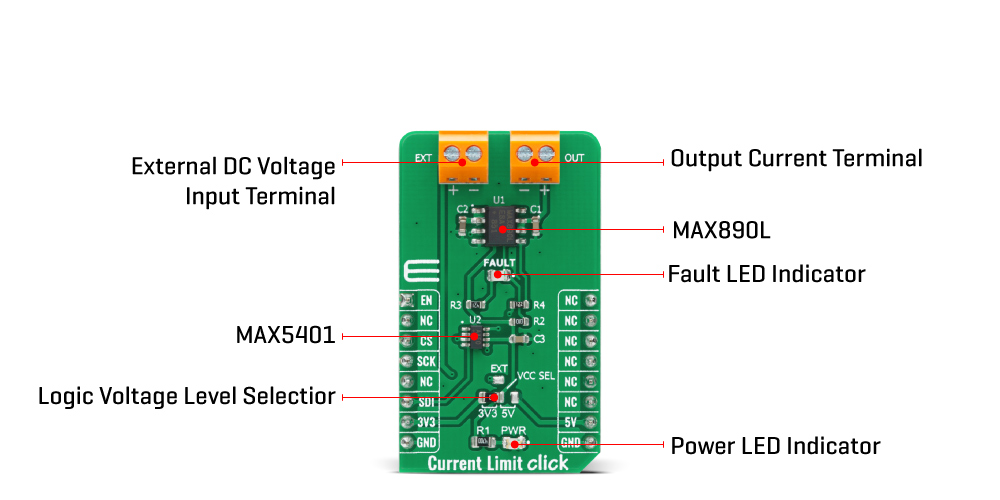
The Current Limit Click Board™ is based on the MAX890L, a high-side low-resistance P-channel switch with the adjustable, accurate current limit system, and thermal shutdown from Analog Devices. The MAX890L limits the output current to a programmed level. When the output current is increased beyond the programmed current limit (1.2A), the current also increases through the internal replica amplifier along with the resistance applied on the SET pin. The current-limit error amplifier compares the voltage across the SET pin resistance to the internal +1.24V reference and regulates the current back to the lesser of the programmed limit (1.2A). This switch is not bidirectional, which means the input voltage must be higher than the output voltage.
The Current Limit Click Board™ is virtually ubiquitous in system control, and provide a safe means for regulating the current delivered to a load circuit. It allows the load current to increase to a programmed limit but no higher. Typically, the current limit is a function of the voltage across an external resistor, and this voltage serves as the reference for an internal current-limiting amplifier. By replacing the resistor with a digital potentiometer, you can easily program the current limit as performed on this Click board™. For this purpose, the digital potentiometer MAX5401 from Analog Devices that communicates with the MCU via 3-Wire SPI serial interface is used to set the resistance on the SET pin of the MAX890L, and thus adjust the current limit for the switch.
The MAX890L provides an open-drain fault output with a red color LED, labelled as FAULT used to indicate when current reaches its limit or when the temperature exceeds +135°C. Besides the fault-indicator pin, the MAX890L also has an active-low Switch-On pin labelled as ON pin of the mikroBUS™ socket used to enable and turn the switch on.
The Current Limit Click Board™ is designed to be operated with both 3.3V and 5V logic voltage levels that can be selected via the VCC SEL jumper. Additionally, there is a possibility in this selection that as a source of logical voltage level, a voltage from an external input terminal in the range from 2.7 to 5.5V can be used. In this way, whether using a logic voltage level from mikroBUS™ or an external voltage supply, this allows for both 3.3V and 5V capable MCUs to use the SPI communication lines properly.
| Type | Power Switch |
| Applications | Can be used for applications in some portable equipment, access bus slots, or with power supplies, protecting them in cases of a short circuit or other overload conditions. |
| On-board modules | The Current Limit Click Board™ is based on the MAX890L, a high-side low-resistance P-channel switch with the adjustable, accurate current limit system, and thermal shutdown from Maxim Integrated. |
| Key Features | Low power consumption, programmable current limit, thermal shutdown, fault indicator output, low quiescent current, and more. |
| Interface | SPI |
| Compatibility | mikroBUS |
| Click board size | M (42.9 x 25.4 mm) |
| Input Voltage | 3.3V or 5V,External |
This table shows how the pinout of the Current Limit Click Board™ corresponds to the pinout on the mikroBUS™ socket (the latter shown in the two middle columns).
| Notes | Pin | Pin | Notes | ||||
|---|---|---|---|---|---|---|---|
| Switch Enable | EN | 1 | AN | PWM | 16 | NC | |
| NC | 2 | RST | INT | 15 | NC | ||
| SPI Chip Select | CS | 3 | CS | RX | 14 | NC | |
| SPI Clock | SCK | 4 | SCK | TX | 13 | NC | |
| NC | 5 | MISO | SCL | 12 | NC | ||
| SPI Data IN | SDI | 6 | MOSI | SDA | 11 | NC | |
| Power Supply | 3.3V | 7 | 3.3V | 5V | 10 | 5V | Power Supply |
| Ground | GND | 8 | GND | GND | 9 | GND | Ground |
| Label | Name | Default | Description |
|---|---|---|---|
| LD1 | PWR | - | Power LED Indicator |
| LD2 | FAULT | - | Fault LED Indicator |
| JP1 | VCC SEL | Left | Power Supply Voltage Selection 3V3/5V/EXT: Left position 3V3, Right position 5V, Top position External Voltage |
| Description | Min | Typ | Max | Unit |
|---|---|---|---|---|
| External Supply Voltage | -0.3 | - | 6 | V |
| Maximum Output Current Limit | - | 1.2 | - | A |
| Operating Temperature Range | -40 | - | +85 | °C |
The 10DOF Click Board™ is a mikroBUS add-on board for enhancing hardware prototypes with 10DOF functionality (10 degrees of freedom). The Click Board™ carries two modules from Bosch: BNO055, a 9-axis absolute orientation sensor and BMP180, a digital pressure sensor.
.
- amazon_main_image: https://www.thedebugstore.com/images/product/lg-current-limit-click-front.jpg - amazon_other_image_1: https://www.thedebugstore.com/images/product/lg-current-limit-click-back.jpg - amazon_other_image_2: https://www.thedebugstore.com/images/product/lg-current-limit-click-fusion.jpg - amazon_other_image_3: https://www.thedebugstore.com/images/product/lg-current-limit-click-shuttle.jpg - amazon_other_image_4: https://www.thedebugstore.com/images/product/lg-current-limit-click-clicker.jpg - amazon_other_image_5: https://www.thedebugstore.com/images/product/lg-current-limit-click-breadboard.jpg - amazon_other_image_6: https://www.thedebugstore.com/images/product/lg-current-limit-click-breadboard.jpg - amazon_browse_node: 428655031 - related_products: MIKROE-3827,MIKROE-4153,MIKROE-3869 - mpn: MIKROE-4271 - backorder_label: If no stock shown above, check availability - badge: - widget:
We provide a library for the Current Limit Click Board™ on our LibStock page, as well as a demo application (example), developed using MikroElektronika compilers. The demo can run on all the main MikroElektronika development boards.
The library covers necessary functions that enables the usage of the Current Limit Click Board™ board. User can check or set current limit or enable/disable the device.
void currentlimit_dev_enable ( uint8_t state ); - Function is used to enable or disable the device.void currentlimit_set_limit ( uint8_t lim_val ); - Function is used to set the current limit with predefined values.void currentlimit_set_limit_calc ( float lim_val ); - Function is used to set the current limit with calculacion.The application is composed of three sections :
void application_task ( )
{
    char inx;

    if ( UART_Rdy_Ptr() )
    {
        inx = UART_Rd_Ptr( );
        inx -=48;
        currentlimit_set_limit( lim_val[ inx - 1 ] );
        mikrobus_logWrite("Data sent successfully!", _LOG_LINE );
    }
}
The full application code, and ready to use projects can be found on our LibStock page.Other mikroE Libraries used in the example:
Depending on the development board you are using, you may need USB UART Click Board™, USB UART 2 Click Board™ or RS232 Click Board™ to connect to your PC, for development systems with no UART to USB interface available on the board. The terminal available in all MikroElektronika compilers, or any other terminal application of your choice, can be used to read the message.
The Current Limit Click Board™ is supported with mikroSDK - MikroElektronika Software Development Kit. To ensure proper operation of mikroSDK compliant Click board™ demo applications, mikroSDK should be downloaded from the LibStock and installed for the compiler you are using.
- attachments: [{"download_file":[{"download_file":"Current Limit Click Board™ Schematic"}],"download_filetype":[{"download_filetype":"pdf"}]},{"download_file":[{"download_file":"Maxim MAX5401 Digital"}],"download_filetype":[{"download_filetype":"pdf"}]},{"download_file":[{"download_file":"Maxim MAC890L Power Switch Datasheet"}],"download_filetype":[{"download_filetype":"pdf"}]}] - device_vendor: Maxim Integrated - device_type: MAX5401EKA+T, MAX890LESA+T - warranty: 12 months - brand: MikroE - key_feature_1: Protects Power Supplies - manufacturer: Mikroelektronika d.o.o. - target_keyword: Current Limit Click Board - brands: gid://shopify/Metaobject/56256004319 - breadcrumbs: ["gid://shopify/Collection/447955239135","gid://shopify/Collection/241680580797","gid://shopify/Collection/241545478333"] - customhs_code: 847330 - detailed_description: {"type":"root","children":[{"type":"heading","level":3,"children":[{"type":"text","value":"How Does The Current Limit Click Board™ Work?"}]},{"type":"paragraph","children":[{"type":"text","value":"The "},{"type":"text","value":"Current Limit Click Board™","bold":true,"italic":true},{"type":"text","value":" is based on the MAX890L, a high-side low-resistance P-channel switch with the adjustable, accurate current limit system, and thermal shutdown from Analog Devices. The MAX890L limits the output current to a programmed level. When the output current is increased beyond the programmed current limit (1.2A), the current also increases through the internal replica amplifier along with the resistance applied on the SET pin. The current-limit error amplifier compares the voltage across the SET pin resistance to the internal +1.24V reference and regulates the current back to the lesser of the programmed limit (1.2A). This switch is not bidirectional, which means the input voltage must be higher than the output voltage."}]},{"type":"paragraph","children":[{"type":"text","value":""}]},{"type":"paragraph","children":[{"type":"text","value":"The "},{"type":"text","value":"Current Limit Click Board™","bold":true},{"type":"text","value":" is virtually ubiquitous in system control, and provide a safe means for regulating the current delivered to a load circuit. It allows the load current to increase to a programmed limit but no higher. Typically, the current limit is a function of the voltage across an external resistor, and this voltage serves as the reference for an internal current-limiting amplifier. By replacing the resistor with a digital potentiometer, you can easily program the current limit as performed on this Click board™. For this purpose, the digital potentiometer MAX5401 from Analog Devices that communicates with the MCU via 3-Wire SPI serial interface is used to set the resistance on the SET pin of the MAX890L, and thus adjust the current limit for the switch."}]},{"type":"paragraph","children":[{"type":"text","value":"The MAX890L provides an open-drain fault output with a red color LED, labelled as FAULT used to indicate when current reaches its limit or when the temperature exceeds +135°C. Besides the fault-indicator pin, the MAX890L also has an active-low Switch-On pin labelled as ON pin of the mikroBUS™ socket used to enable and turn the switch on."}]},{"type":"paragraph","children":[{"type":"text","value":"The "},{"type":"text","value":"Current Limit Click Board™","bold":true},{"type":"text","value":" is designed to be operated with both 3.3V and 5V logic voltage levels that can be selected via the VCC SEL jumper. Additionally, there is a possibility in this selection that as a source of logical voltage level, a voltage from an external input terminal in the range from 2.7 to 5.5V can be used. In this way, whether using a logic voltage level from mikroBUS™ or an external voltage supply, this allows for both 3.3V and 5V capable MCUs to use the SPI communication lines properly."}]},{"type":"heading","level":3,"children":[{"type":"text","value":"SPECIFICATIONS"}]},{"type":"paragraph","children":[{"type":"text","value":"Type\nPower Switch\nApplications\nCan be used for applications in some portable equipment, access bus slots, or with power supplies, protecting them in cases of a short circuit or other overload conditions.\nOn-board modules\nThe Current Limit Click Board™ is based on the MAX890L, a high-side low-resistance P-channel switch with the adjustable, accurate current limit system, and thermal shutdown from Maxim Integrated.\nKey Features\nLow power consumption, programmable current limit, thermal shutdown, fault indicator output, low quiescent current, and more.\nInterface\nSPI\nCompatibility\nmikroBUS\nClick board size\nM (42.9 x 25.4 mm)\nInput Voltage\n3.3V or 5V,External"}]},{"type":"heading","level":3,"children":[{"type":"text","value":"PINOUT DIAGRAM"}]},{"type":"paragraph","children":[{"type":"text","value":"This table shows how the pinout of the "},{"type":"text","value":"Current Limit Click Board™","bold":true},{"type":"text","value":" corresponds to the pinout on the mikroBUS™ socket (the latter shown in the two middle columns)."}]},{"type":"paragraph","children":[{"type":"text","value":"Notes\nPin\nPin\nNotes\nSwitch Enable\nEN\n1\nAN\nPWM\n16\nNC\nNC\n2\nRST\nINT\n15\nNC\nSPI Chip Select\nCS\n3\nCS\nRX\n14\nNC\nSPI Clock\nSCK\n4\nSCK\nTX\n13\nNC\nNC\n5\nMISO\nSCL\n12\nNC\nSPI Data IN\nSDI\n6\nMOSI\nSDA\n11\nNC\nPower Supply\n3.3V\n7\n3.3V\n5V\n10\n5V\nPower Supply\nGround\nGND\n8\nGND\nGND\n9\nGND\nGround"}]},{"type":"heading","level":3,"children":[{"type":"text","value":"ONBOARD SETTINGS AND INDICATORS"}]},{"type":"paragraph","children":[{"type":"text","value":"Label\nName\nDefault\nDescription\nLD1\nPWR\n-\nPower LED Indicator\nLD2\nFAULT\n-\nFault LED Indicator\nJP1\nVCC SEL\nLeft\nPower Supply Voltage Selection 3V3/5V/EXT: Left position 3V3, Right position 5V, Top position External Voltage"}]},{"type":"heading","level":3,"children":[{"type":"text","value":"CURRENT LIMIT CLICK ELECTRICAL SPECIFICATIONS"}]},{"type":"paragraph","children":[{"type":"text","value":"Description\nMin\nTyp\nMax\nUnit\nExternal Supply Voltage\n-0.3\n-\n6\nV\nMaximum Output Current Limit\n-\n1.2\n-\nA\nOperating Temperature Range\n-40\n-\n+85\n°C"}]},{"type":"heading","level":3,"children":[{"type":"text","value":" "}]}]} - summary:The Current Limit Click Board™ is a compact add-on board that contains a low-voltage, P-channel MOSFET power switch intended for high-side load switching applications. This board features the MAX890L, a low-resistance power switch with an adjustable, accurate current limit system, and thermal shutdown from Maxim Integrated. Its internal current-limiting circuitry protects the input supply against overload, while thermal protection limits power dissipation. The maximum current limit is 1.2A and can be programmed through a digital potentiometer MAX5401. The quiescent supply current has a low value of 10μA in the active state, while in its off state the supply current decreases to 0.1μA. This Click Board™ is suitable for applications in some portable equipment, access bus slots, or with power supplies, protecting them in cases of a short circuit or other overload conditions.
The Current Limit Click Board™ is supported by a mikroSDK compliant library, which includes functions that simplify software development. This Click Board™ comes as a fully tested product, ready to be used on a system equipped with the mikroBUS™ socket.