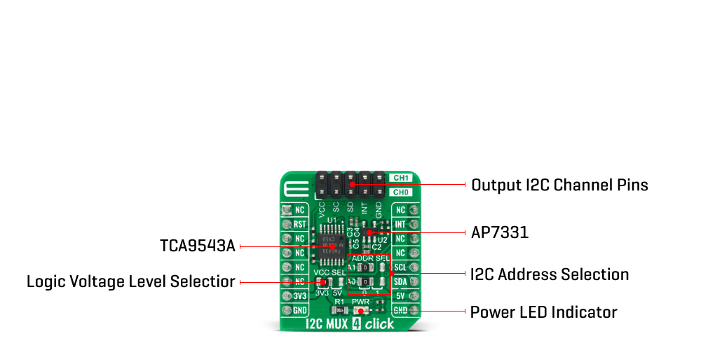
The I2C MUX 4 Click Board™ is based on the TCA9543APWR, a 2-channel, bidirectional translating I2C switch from Texas Instruments. The master SCL/SDA signal pair is directed to two channels of slave devices SC0/SD0 - SC1/SD1 where either individual channel or both channels can be selected determined by the programmable control register. The TCA9543APWR supports interrupt signals for the Master to detect an interrupt that can result from any of the slave devices connected to the interrupt pins on the output I2C channel header. It features I2C control using a single 8-bit control register in which bits 1 and 0 control the enabling and disabling of the two switch channels of I2C data flow, it supports a reset function, hot insertion, and has all switch channels deselected during Power-Up.
The I2C MUX 4 Click Board™ includes a low dropout linear regulator AP7331 from Diodes Incorporated to provide the 2.45V supply voltage for the TCA9543APWR. When the TCA9543APWR is turned on for the first time or anytime the device needs to be reset by cycling the power supply, which means that the Power-On reset requirements must be followed to ensure the I2C bus logic is initialized properly. The TCA9543APWR can also be reset to its default conditions by using the Power-On reset feature in the event of a glitch or data corruption.
The I2C MUX 4 Click Board™ communicates with MCU using the standard I2C 2-Wire interface that supports Standard-Mode (100 kHz) and Fast-Mode (400 kHz) operation. The TCA9543APWR generates a programmable interrupt signal routed on the INT pin of the mikroBUS™ used for the Master to detect an interrupt which can result from any of the slave devices connected to the output I2C channel pins. It also has two address pins that allow the choice of the least significant bit (LSB) of its I2C slave address which can be done by using the SMD jumper labelled as ADDR SEL, and a Reset function routed on the RST pin of the mikroBUS™ socket used to recover the TCA9543APWR from a bus-fault condition.
The I2C MUX 4 Click Board™ is designed to be operated with both 3.3V and 5V logic voltage levels that can be selected via VCC SEL jumper. This allows for both 3.3V and 5V capable MCUs to use the I2C communication lines properly.
| Type | I2C |
| Applications | Can be used with I2C interfaces for applications such as fault isolation, address conflict, level translation, or broadcast communication. |
| On-board modules | The I2C MUX 4 Click Board™ is based on the TCA9543APWR, a 2-channel, bidirectional translating I2C switch from Texas Instruments. |
| Key Features | 1-of-2 bidirectional translating switches, low Stand-By current, support hot insertion, deselected channels during Power-Up, and more. |
| Interface | I2C |
| Compatibility | mikroBUS |
| Click board size | S (28.6 x 25.4 mm) |
| Input Voltage | 3.3V or 5V |
This table shows how the pinout of the I2C MUX 4 Click Board™ corresponds to the pinout on the mikroBUS™ socket (the latter shown in the two middle columns).
| Notes | Pin | Pin | Notes | ||||
|---|---|---|---|---|---|---|---|
| NC | 1 | AN | PWM | 16 | NC | ||
| Reset | RST | 2 | RST | INT | 15 | INT | Interrupt |
| NC | 3 | CS | RX | 14 | NC | ||
| NC | 4 | SCK | TX | 13 | NC | ||
| NC | 5 | MISO | SCL | 12 | SCL | I2C Clock | |
| NC | 6 | MOSI | SDA | 11 | SDA | I2C Data | |
| Power Supply | 3.3V | 7 | 3.3V | 5V | 10 | 5V | Power Supply |
| Ground | GND | 8 | GND | GND | 9 | GND | Ground |
| Label | Name | Default | Description |
|---|---|---|---|
| LD1 | PWR | - | Power LED Indicator |
| JP1 | VCC SEL | Left | Power Supply Voltage Selection 3V3/5V: Left position 3V3, Right position 5V |
| JP2-JP3 | ADDR SEL | Left | Communication Interface Selection: Left position 0, Right position 1 |
| J1 | - | - | Output I2C Channel Pins |
| Description | Min | Typ | Max | Unit |
|---|---|---|---|---|
| Supply Voltage | -0.5 | - | 7 | V |
| Maximum Output Current | - | - | ±20 | mA |
| Maximum Frequency | - | - | 400 | kHz |
| Maximum Power Dissipation | - | - | 400 | mW |
| Operating Temperature Range | -40 | - | +85 | °C |
With its ultra-low power consumption, onboard data processing, output data lowpass filtering, and ability to detect many different events, the Accel 5 click is a perfect solution for IoT applications. It can also be used to develop applications for wearables, where the BMA400 sensor shows its true potential, offering an ultra-low power always-on operation with no functionality compromises. In general, Accel 5 click can be used wherever a reliable detection of the acceleration-related events is needed: smart home applications, IoT applications, drop detection for warranty logging, power management based on motion, and similar.
The Accel 5 Click Board Is based around the BMA400, an ultra-low power triaxial accelerometer sensor, from Bosch Sensortech. This sensor has many features perfectly suited for IoT applications and wearables, offering a good balance between the performance and the power consumption. One of its key features is its ultra-low power consumption, allowing it to be used in various always-on low power applications. To improve the battery life even more, this sensor also features a Sleep mode when the sensor current consumption is in magnitude of few hundred nanoamperes.
This sensor can measure the acceleration in ranges of ±2 g, ±4 g, ±8, and ±16 g. It also offers lowpass filtering of the output data, in the range from 0.48 x ODR (Output Data Refresh rate), up to maximal ODR frequency of 800Hz. An internal 12bit A/D converter ensures reliable and low noise operation, so that the data coming from the internal MEMS remains clean and accurate. Three power modes allow customized balance between the power consumption and performance. An extensive integrated interrupt engine offers many distinctive functionalities, such as the automatic enter/exit Low Power mode, advanced actions detection such as the running, walking, several other features such as the step counting…
After the POR (Power ON Reset) event, the device stays in the Sleep mode. In Sleep mode, the sensor practically does not consume any power (about 300nA), but the sensor functionality is completely suspended. To use the sensor, it has to be either in Low Power mode, where it uses a fixed Output Data Refresh (ODR) of 25Hz, or in the Normal mode. Some options are exclusive only to Normal mode, such as the step counting detection, output filtering and so on. Normal mode still uses power conservative, allowing the device to be used in the Always-ON low power applications.
While operating in Normal mode, two filters are available for the data filtering. The filters can be applied either to the output registers, the FIFO engine, or can be used to process the interrupt data. The first filter can be used to obtain data rates from 12.5Hz up to 800Hz, which is defined by the filter registers, while the second filter offers fixed frequency of 100Hz, superimposed by a frequency of 1Hz. The output noise is affected by the ODR frequency.
Acceleration data is available in 12-bit format from both the data registers and the internal FIFO buffer of 1kb. The FIFO buffer can be used for more complex calculations or timed readings. Writing to FIFO buffer is only allowed in the Normal mode, while it can be read in the Low power mode, too. The interrupt engine facilitates the complete FIFO buffer, triggering an interrupt for several FIFO events: overflow event, watermark event, almost full event, and so on.
The BMA400 sensor contains an integrated timer, which can be used along with the interrupts to be used for the auto Wakeup or auto Power down functions. The automatic functions are a part of the sensor power management. The automatic mode changes can be set either to an acceleration interrupt after a specified threshold is reached, or it can be set to a timer interrupt: when the timer expires, the interrupt is generated, and the power mode is switched.
An extensive interrupt engine offers two layers of interrupts. It offers basic interrupts, including some basic functions, such as the Data Ready interrupt, FIFO buffer related interrupts and the Wakeup event interrupt. Basic interrupts also report Interrupt overrun event, where too many interrupts are competing, so that the sensor is not able to process them all.
Besides the basic interrupts, the interrupt engine offers some more sophisticated, advanced interrupts, that include detection all of the activities: tap/double tap, step counting, activity changed, orientation changed, and two generic interrupts. The advanced interrupts require a certain ODR rate and can be used in the Normal mode exclusively, while basic interrupts offer more rudimental control over events.
The advanced interrupt engine can use two programmable interrupt pins. Both of these pins can be assigned with any interrupt source and can be either LOW or HIGH on interrupt, depending on settings in appropriate registers. These two pins are routed to INT and PWM pins of the mikroBUS™, and are labeled as IT1 and IT2, respectively.Besides the acceleration MEMS and complementary analog front-end circuitry, the BMA400 sensor also has an integrated temperature sensor. It is updated every 160ms and sampled with the 8-bit resolution. Thermal data is always available, except when the device is in the Sleep mode.
Accel 5 click offers two communication interfaces. It can be used with either I2C or SPI. The onboard SMD jumpers labeled as SEL COM allow switching between the two interfaces. Note that all the jumpers have to be positioned either to I2C or to SPI position. When I2C interface is selected, an additional SMD jumper labeled as the I2C ADD becomes available, determining the least significant bit of the BMA400 I2C address. The Click board™ should be interfaced only with MCUs that operate on 3.3V
We provide a library for the I2C MUX 4 Click Board™ on our LibStock page, as well as a demo application (example), developed using MikroElektronika compilers. The demo can run on all the main MikroElektronika development boards.
The library covers all the necessary functions to control the I2C MUX 4 Click Board™. A library performs the communication with the TCA9543A Low Voltage 2-Channel I2C Bus Switch via I2C interface.
void i2cmux4_power_on ( uint8_t enable ) - Power On function.void i2cmux4_set_channel ( uint8_t sel_ch, uint8_t ch_slave_addr ) - Set channel function.uint8_t i2cmux4_check_int ( void ) - Check interrupt function.The application is composed of three sections :
void application_task ( )
{
 // CH 0 - 6DOF IMU 12 Click Board™
 i2cmux4_set_channel( I2CMUX4_SEL_CH_0, 0x68 );
 Delay_ms( 100 );
 i2cmux4_rmt_read_bytes( 0x00, &rx_data, 1 );
 Delay_ms( 100 );
 ByteToHex( rx_data, log_text );
 mikrobus_logWrite( " 6DOF IMU 12 Click Board™ ", _LOG_LINE );
 mikrobus_logWrite( "- - - - - - - - - - - -", _LOG_LINE );
 mikrobus_logWrite( " ID = 0x", _LOG_TEXT );
 mikrobus_logWrite( log_text, _LOG_LINE );
 mikrobus_logWrite( "-----------------------", _LOG_LINE );

 Delay_ms( 1000 );

 // CH 1 - RTC 10 Click Board™
 i2cmux4_set_channel( I2CMUX4_SEL_CH_1, 0x68 );
 Delay_ms( 100 );
 i2cmux4_rmt_read_bytes( 0x0F, &rx_data, 1 );
 Delay_ms( 100 );
 ByteToHex( rx_data, log_text );
 mikrobus_logWrite( " RTC 10 Click Board™ ", _LOG_LINE );
 mikrobus_logWrite( "- - - - - - - - - - - -", _LOG_LINE );
 mikrobus_logWrite( " ID = 0x", _LOG_TEXT );
 mikrobus_logWrite( log_text, _LOG_LINE );
 mikrobus_logWrite( "-----------------------", _LOG_LINE );

 Delay_ms( 1000 );
}
The full application code, and ready to use projects can be found on our LibStock page.
Other mikroE Libraries used in the example:
Depending on the development board you are using, you may need USB UART Click Board™, USB UART 2 Click Board™ or RS232 Click Board™ to connect to your PC, for development systems with no UART to USB interface available on the board. The terminal available in all MikroElektronika compilers, or any other terminal application of your choice, can be used to read the message.
The I2C MUX 4 Click Board™ is supported with mikroSDK - MikroElektronika Software Development Kit. To ensure proper operation of mikroSDK compliant Click board™ demo applications, mikroSDK should be downloaded from the LibStock and installed for the compiler you are using.
- attachments: [{"download_file":[{"download_file":"I2C MUX 4 Click Board™ Schematic"}],"download_filetype":[{"download_filetype":"pdf"}]},{"download_file":[{"download_file":"Texas Instruments TCA9543APWR I2C Bus Switch Datasheet"}],"download_filetype":[{"download_filetype":"pdf"}]},{"download_file":[{"download_file":"Diodes Inc AP7331 LDO Regulator Datasheet"}],"download_filetype":[{"download_filetype":"pdf"}]}] - device_vendor: Texas Instruments - device_type: TCA9543APWR - warranty: 12 months - brand: MikroE - key_feature_1: Multiplexer For Solving I2C Address Conflicts - manufacturer: Mikroelektronika d.o.o. - target_keyword: I2C MUX 4 Click Board - brands: gid://shopify/Metaobject/56256004319 - breadcrumbs: ["gid://shopify/Collection/447955239135","gid://shopify/Collection/241680580797","gid://shopify/Collection/241546100925"] - customhs_code: 847330 - detailed_description: {"type":"root","children":[{"type":"heading","level":3,"children":[{"type":"text","value":"How Does The I2C MUX 4 Click Board™ Work?"}]},{"type":"paragraph","children":[{"type":"text","value":"The"},{"type":"text","value":" I2C MUX 4 Click Board™","bold":true,"italic":true},{"type":"text","value":" is based on the TCA9543APWR, a 2-channel, bidirectional translating I2C switch from Texas Instruments. The master SCL/SDA signal pair is directed to two channels of slave devices SC0/SD0 - SC1/SD1 where either individual channel or both channels can be selected determined by the programmable control register. The TCA9543APWR supports interrupt signals for the Master to detect an interrupt that can result from any of the slave devices connected to the interrupt pins on the output I2C channel header. It features I2C control using a single 8-bit control register in which bits 1 and 0 control the enabling and disabling of the two switch channels of I2C data flow, it supports a reset function, hot insertion, and has all switch channels deselected during Power-Up."}]},{"type":"paragraph","children":[{"type":"text","value":""}]},{"type":"paragraph","children":[{"type":"text","value":"The "},{"type":"text","value":"I2C MUX 4 Click Board™","bold":true},{"type":"text","value":" includes a low dropout linear regulator AP7331 from Diodes Incorporated to provide the 2.45V supply voltage for the TCA9543APWR. When the TCA9543APWR is turned on for the first time or anytime the device needs to be reset by cycling the power supply, which means that the Power-On reset requirements must be followed to ensure the I2C bus logic is initialized properly. The TCA9543APWR can also be reset to its default conditions by using the Power-On reset feature in the event of a glitch or data corruption."}]},{"type":"paragraph","children":[{"type":"text","value":"The "},{"type":"text","value":"I2C MUX 4 Click Board™","bold":true},{"type":"text","value":" communicates with MCU using the standard I2C 2-Wire interface that supports Standard-Mode (100 kHz) and Fast-Mode (400 kHz) operation. The TCA9543APWR generates a programmable interrupt signal routed on the INT pin of the mikroBUS™ used for the Master to detect an interrupt which can result from any of the slave devices connected to the output I2C channel pins. It also has two address pins that allow the choice of the least significant bit (LSB) of its I2C slave address which can be done by using the SMD jumper labelled as ADDR SEL, and a Reset function routed on the RST pin of the mikroBUS™ socket used to recover the TCA9543APWR from a bus-fault condition."}]},{"type":"paragraph","children":[{"type":"text","value":"The "},{"type":"text","value":"I2C MUX 4 Click Board™","bold":true},{"type":"text","value":" is designed to be operated with both 3.3V and 5V logic voltage levels that can be selected via VCC SEL jumper. This allows for both 3.3V and 5V capable MCUs to use the I2C communication lines properly."}]},{"type":"heading","level":3,"children":[{"type":"text","value":"SPECIFICATIONS"}]},{"type":"paragraph","children":[{"type":"text","value":"Type\nI2C\nApplications\nCan be used with I2C interfaces for applications such as fault isolation, address conflict, level translation, or broadcast communication.\nOn-board modules\nThe I2C MUX 4 Click Board™ is based on the TCA9543APWR, a 2-channel, bidirectional translating I2C switch from Texas Instruments.\nKey Features\n1-of-2 bidirectional translating switches, low Stand-By current, support hot insertion, deselected channels during Power-Up, and more.\nInterface\nI2C\nCompatibility\nmikroBUS\nClick board size\nS (28.6 x 25.4 mm)\nInput Voltage\n3.3V or 5V"}]},{"type":"heading","level":3,"children":[{"type":"text","value":"PINOUT DIAGRAM"}]},{"type":"paragraph","children":[{"type":"text","value":"This table shows how the pinout of the "},{"type":"text","value":"I2C MUX 4 Click Board™","bold":true},{"type":"text","value":" corresponds to the pinout on the mikroBUS™ socket (the latter shown in the two middle columns)."}]},{"type":"paragraph","children":[{"type":"text","value":"Notes\nPin\nPin\nNotes\nNC\n1\nAN\nPWM\n16\nNC\nReset\nRST\n2\nRST\nINT\n15\nINT\nInterrupt\nNC\n3\nCS\nRX\n14\nNC\nNC\n4\nSCK\nTX\n13\nNC\nNC\n5\nMISO\nSCL\n12\nSCL\nI2C Clock\nNC\n6\nMOSI\nSDA\n11\nSDA\nI2C Data\nPower Supply\n3.3V\n7\n3.3V\n5V\n10\n5V\nPower Supply\nGround\nGND\n8\nGND\nGND\n9\nGND\nGround"}]},{"type":"heading","level":3,"children":[{"type":"text","value":"ONBOARD SETTINGS AND INDICATORS"}]},{"type":"paragraph","children":[{"type":"text","value":"Label\nName\nDefault\nDescription\nLD1\nPWR\n-\nPower LED Indicator\nJP1\nVCC SEL\nLeft\nPower Supply Voltage Selection 3V3/5V: Left position 3V3, Right position 5V\nJP2-JP3\nADDR SEL\nLeft\nCommunication Interface Selection: Left position 0, Right position 1\nJ1\n-\n-\nOutput I2C Channel Pins"}]},{"type":"heading","level":3,"children":[{"type":"text","value":"I2C MUX 4 CLICK ELECTRICAL SPECIFICATIONS"}]},{"type":"paragraph","children":[{"type":"text","value":"Description\nMin\nTyp\nMax\nUnit\nSupply Voltage\n-0.5\n-\n7\nV\nMaximum Output Current\n-\n-\n±20\nmA\nMaximum Frequency\n-\n-\n400\nkHz\nMaximum Power Dissipation\n-\n-\n400\nmW\nOperating Temperature Range\n-40\n-\n+85\n°C"}]},{"type":"heading","level":3,"children":[{"type":"text","value":" "}]}]} - summary:The I2C MUX 4 Click Board™ is a compact add-on board that contains a dual bidirectional translating switch dedicated for applications with I2C slave address conflicts. This board features the TCA9543APWR, a low voltage 2-channel I2C bus switch with interrupt logic from Texas Instruments. The master SCL/SDA signals are directed to two downstream pairs, or channels, where either individual SCL/SDA channel or both channels can be selected by setting the programmable control register. It has two interrupts and a Reset input which allows the TCA9543A to recover from a situation where one of the downstream I2C buses is stuck in a low state. This Click Board™ is suitable to work with I2C interfaces for applications such as fault isolation, address conflict, level translation, or broadcast communication.
The I2C MUX 4 Click Board™ is supported by a mikroSDK compliant library, which includes functions that simplify software development. This Click Board™ comes as a fully tested product, ready to be used on a system equipped with the mikroBUS™ socket.