# Title: DotMatrix R Click Board™
## Description: How Does The Dot Matrix R Click Board™ Work? The Dot Matrix R Click Board™ is a high performance, easy to use dot matrix display driven by on-board CMOS IC. Each display can be directly interfaced with a microprocessor, thus eliminating the need for cumbersome interface components. The serial IC interface allows higher character count information displays with a minimum of data lines. The easy to read 5x7 pixel format allows the display of upper case, lower case, Katakana, and custom user-defined characters. These displays are stackable in the x- and y-directions, making them ideal for high character count displays. Typical applications include telecommunication equipment, portable data entry devices, computer peripherals, medical equipment, test equipment, business machines, avionics, industrial controls, etc. Featured LED display HCMS-3906 consists of LEDs that are configured as 5x7 font characters driven in groups of 4 characters per IC. Each IC consists of a 160-bit shift register (the Dot Register), two 7-bit Control Words, and refresh circuitry. The Dot Register contents are mapped on a one-to-one basis to the display. Thus, an individual Dot Register bit uniquely controls a single LED. Reset initializes the Control Registers (sets all Control Register bits to logic low) and places the display in the sleep mode. The Dot Registers are not cleared upon power-on or by Reset. After power-on, the Dot Register contents are random; however, Reset will put the display in sleep mode, thereby blanking the LEDs. The Control Register and the Control Words are cleared to all zeros by Reset. To operate the display after being Reset, load the Dot Register with logic lows. Then load Control Word 0 with the desired brightness level and set the sleep mode bit to logic high. The Dot Register holds the pattern to be displayed by the LEDs. First RS is brought low, then CE is brought low. Next, each successive rising CLK edge will shift in the data at the DIN pin. Loading a logic high will turn the corresponding LED on; a logic low turns the LED off. When all 160 bits have been loaded, CE is brought to logic high. When CLK is next brought to logic low, new data is latched into the display dot drivers. Loading data into the Dot Register takes place while the previous data is displayed and eliminates the need to blank the display while loading data. In a 4-character display, the 160 bits are arranged as 20 columns by 8 rows. This array can be conceptualized as four 5x8 dot matrix character locations, but only 7 of the 8 rows have LEDs. The bottom row (row 0) is not used. Thus, latch location 0 is never displayed. Column 0 controls the left-most column. Data from Dot Latch locations 0-7 determine whether or not pixels in Column 0 are turned-on or turned-off. Therefore, the lower left pixel is turned on when a logic high is stored in Dot Latch location 1. Characters are loaded in serially, with the left-most character being loaded first and the rightmost character being loaded last. By loading one character at a time and latching the data before loading the next character, the figures will appear to scroll from right to left. The Control Register allows software modification of the IC's operation and consists of two independent 7-bit control words. Bit D7 in the shift register selects one of the two 7-bit control words. Control Word 0 performs pulse width modulation, pixel map, brightness control, peak pixel current brightness control, and sleep mode. Control Word 1 sets serial/simultaneous data out mode, and external oscillator prescaler. Each function is independent of the others. The Dot Matrix R Click Board™ can be supplied and interfaced with both 3.3V and 5V without the need for any external components. The onboard SMD jumper labelled as VCC SEL allows voltage selection for interfacing with both 3.3V and 5V microcontrollers. SPECIFICATIONS Type LED Matrix Applications Dot Matrix R Click Board™ allows simple and fast development of various applications, which require displaying of characters, numbers, or both. On-board modules Dot Matrix R Click Board™ uses the HCMS-3906, a high performance, easy to use alphanumeric display, from Broadcom Limited. Key Features Easy to use four-digit 5x7 dot matrix display with dense and brightly lit pixel elements, interfaced directly with the microprocessor, serial input, convenient brightness controls. Interface GPIO,SPI Compatibility mikroBUS Click board size M (42.9 x 25.4 mm) Input Voltage 3.3V or 5V PINOUT DIAGRAM This table shows how the pinout of the Dot Matrix R Click Board™ corresponds to the pinout on the mikroBUS™ socket (the latter shown in the two middle columns). Notes Pin Pin Notes Register Select RS 1 AN PWM 16 BL Display Blank Reset RST 2 RST INT 15 NC Chip Enable CS 3 CS RX 14 NC Clock Input SCK 4 SCK TX 13 NC NC 5 MISO SCL 12 NC Data IN SDI 6 MOSI SDA 11 NC Power Supply 3.3V 7 3.3V 5V 10 5V Power Supply Ground GND 8 GND GND 9 GND Ground ONBOARD SETTINGS AND INDICATORS Label Name Default Description LD1 PWR - Power LED Indicator JP1 VCC SEL Left Power Supply Voltage Selection 3V3/5V, left position 3v3, right position 5v
## Product type: Click Board
## Vendor: Mikroelektronika d.o.o.
## Tags: Broadcom Limited, Click Board, Display, Display Interface, LED Matrix, MikroE
## Price range: 60.2 - 60.2 GBP
## Link: https://thedebugstore.com/products/mikroe-4169-dot-matrix-r-click-board-uk
## Compare-at price range: 86.0 - 86.0 GBP
## Options
- Title: Default Title
## Collections
- [New Products](https://thedebugstore.com/a/llms/collections/new-products-debug-store)
- [Mikroelektronika d.o.o. (MikroE)](https://thedebugstore.com/a/llms/collections/mikroelektronika-catalogue-uk)
- [Broadcom Device Support: Development Boards & Tools | Debug Store](https://thedebugstore.com/a/llms/collections/devices-broadcom-limited-avago)
- [Display & Interface Click Boards™](https://thedebugstore.com/a/llms/collections/display-interface-click-boards-catalogue)
- [MikroE Click Boards™](https://thedebugstore.com/a/llms/collections/mikroe-click-boards-catalogue-uk)
- [Displays](https://thedebugstore.com/a/llms/collections/displays-catalogue-uk)
- [Boards](https://thedebugstore.com/a/llms/collections/circuit-boards-catalogue)
- [LED Matrix Click Boards™](https://thedebugstore.com/a/llms/collections/led-matrix-click-boards-catalogue)
- [Click Boards™ Summer Sale](https://thedebugstore.com/a/llms/collections/inventory-sale)
- [MikroE Sale](https://thedebugstore.com/a/llms/collections/mikroe-sale)
- [MIKROE Stock](https://thedebugstore.com/a/llms/collections/mikroe-products-in-stock-sale)
## Variants
- Default Title, SKU: MIKROE-4169, Available: yes, Inventory: 1
## Metafields
- full_description: How Does The Dot Matrix R Click Board™ Work?
The Dot Matrix R Click Board™ is a high performance, easy to use dot matrix display driven by on-board CMOS IC. Each display can be directly interfaced with a microprocessor, thus eliminating the need for cumbersome interface components. The serial IC interface allows higher character count information displays with a minimum of data lines. The easy to read 5x7 pixel format allows the display of upper case, lower case, Katakana, and custom user-defined characters. These displays are stackable in the x- and y-directions, making them ideal for high character count displays. Typical applications include telecommunication equipment, portable data entry devices, computer peripherals, medical equipment, test equipment, business machines, avionics, industrial controls, etc.
Featured LED display HCMS-3906 consists of LEDs that are configured as 5x7 font characters driven in groups of 4 characters per IC. Each IC consists of a 160-bit shift register (the Dot Register), two 7-bit Control Words, and refresh circuitry. The Dot Register contents are mapped on a one-to-one basis to the display. Thus, an individual Dot Register bit uniquely controls a single LED. Reset initializes the Control Registers (sets all Control Register bits to logic low) and places the display in the sleep mode. The Dot Registers are not cleared upon power-on or by Reset. After power-on, the Dot Register contents are random; however, Reset will put the display in sleep mode, thereby blanking the LEDs. The Control Register and the Control Words are cleared to all zeros by Reset. To operate the display after being Reset, load the Dot Register with logic lows. Then load Control Word 0 with the desired brightness level and set the sleep mode bit to logic high.
The Dot Register holds the pattern to be displayed by the LEDs. First RS is brought low, then CE is brought low. Next, each successive rising CLK edge will shift in the data at the DIN pin. Loading a logic high will turn the corresponding LED on; a logic low turns the LED off. When all 160 bits have been loaded, CE is brought to logic high. When CLK is next brought to logic low, new data is latched into the display dot drivers. Loading data into the Dot Register takes place while the previous data is displayed and eliminates the need to blank the display while loading data.
In a 4-character display, the 160 bits are arranged as 20 columns by 8 rows. This array can be conceptualized as four 5x8 dot matrix character locations, but only 7 of the 8 rows have LEDs. The bottom row (row 0) is not used. Thus, latch location 0 is never displayed. Column 0 controls the left-most column. Data from Dot Latch locations 0-7 determine whether or not pixels in Column 0 are turned-on or turned-off. Therefore, the lower left pixel is turned on when a logic high is stored in Dot Latch location 1. Characters are loaded in serially, with the left-most character being loaded first and the rightmost character being loaded last. By loading one character at a time and latching the data before loading the next character, the figures will appear to scroll from right to left.
The Control Register allows software modification of the IC's operation and consists of two independent 7-bit control words. Bit D7 in the shift register selects one of the two 7-bit control words. Control Word 0 performs pulse width modulation, pixel map, brightness control, peak pixel current brightness control, and sleep mode. Control Word 1 sets serial/simultaneous data out mode, and external oscillator prescaler. Each function is independent of the others.
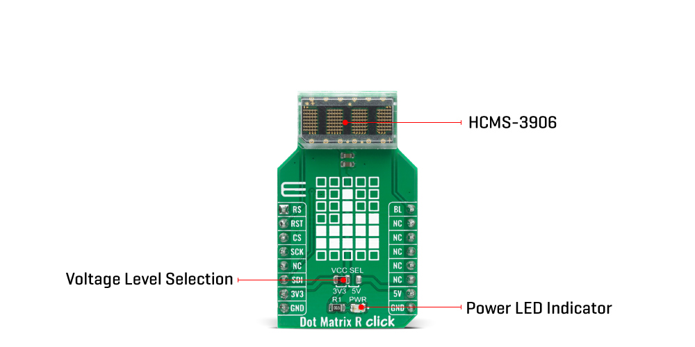
The Dot Matrix R Click Board™ can be supplied and interfaced with both 3.3V and 5V without the need for any external components. The onboard SMD jumper labelled as VCC SEL allows voltage selection for interfacing with both 3.3V and 5V microcontrollers.
SPECIFICATIONS
| Type |
LED Matrix |
| Applications |
Dot Matrix R Click Board™ allows simple and fast development of various applications, which require displaying of characters, numbers, or both. |
| On-board modules |
Dot Matrix R Click Board™ uses the HCMS-3906, a high performance, easy to use alphanumeric display, from Broadcom Limited. |
| Key Features |
Easy to use four-digit 5x7 dot matrix display with dense and brightly lit pixel elements, interfaced directly with the microprocessor, serial input, convenient brightness controls. |
| Interface |
GPIO,SPI |
| Compatibility |
mikroBUS |
| Click board size |
M (42.9 x 25.4 mm) |
| Input Voltage |
3.3V or 5V |
PINOUT DIAGRAM
This table shows how the pinout of the Dot Matrix R Click Board™ corresponds to the pinout on the mikroBUS™ socket (the latter shown in the two middle columns).
| Notes |
Pin |
 |
Pin |
Notes |
| Register Select |
RS |
1 |
AN |
PWM |
16 |
BL |
Display Blank |
| Reset |
RST |
2 |
RST |
INT |
15 |
NC |
| Chip Enable |
CS |
3 |
CS |
RX |
14 |
NC |
| Clock Input |
SCK |
4 |
SCK |
TX |
13 |
NC |
| NC |
5 |
MISO |
SCL |
12 |
NC |
| Data IN |
SDI |
6 |
MOSI |
SDA |
11 |
NC |
| Power Supply |
3.3V |
7 |
3.3V |
5V |
10 |
5V |
Power Supply |
| Ground |
GND |
8 |
GND |
GND |
9 |
GND |
Ground |
ONBOARD SETTINGS AND INDICATORS
| Label |
Name |
Default |
Description |
| LD1 |
PWR |
- |
Power LED Indicator |
| JP1 |
VCC SEL |
Left |
Power Supply Voltage Selection 3V3/5V, left position 3v3, right position 5v |
- description_tag: The Dot Matrix R Click Board™ is a display device based on a four-digit dot matrix display module, labelled as HCMS-3906 from a company Avago (Broadcom Inc). Available from Debug Store UK.
- title_tag: MikroE Dot Matrix R Click Board™ (MIKROE-4169)
- manufacturer: Mikroelektronika d.o.o.
- warranty: 12 months
- amazon_enable: TRUE
- amazon_title: Dot Matrix R Click Board
- amazon_product_type: computercomponent
- amazon_block: FALSE
- amazon_prime_enable: FALSE
- amazon_search: MikroElektronika Microelectronica MIKROE-1100
- amazon_uk_price: 48.4
- amazon_uk_currency: GBP
- amazon_de_currency: EUR
- amazon_de_price: 54.692
- amazon_fr_currency: EUR
- amazon_fr_price: 54.692
- amazon_es_currency: EUR
- amazon_es_price: 54.692
- amazon_nl_currency: EUR
- amazon_nl_price: 54.692
- amazon_it_currency: EUR
- amazon_it_price: 54.692
- amazon_se_curency: SEK
- amazon_se_price: 551.76
- amazon_product_id: 8606018717897
- amazon_product_id_type: EAN
- amazon_update: Update
- amazon_short_description: The Dot Matrix R Click Board™ is a display device Click Board™ based on a four-digit dot matrix display module, labeled as HCMS-3906 from a company Avago (Broadcom Inc). The module holds four 5x7 dot matrices, with very closely spaced, bright red pixel elements. Characters are very clearly displayed as a result. Pixels emit a bright red colour when lit, which makes the display readable in any condition. Each display can be directly interfaced with a microprocessor, thus eliminating the need for cumbersome interface components. The serial IC interface allows higher character count information displays with a minimum of data lines. The easy to read 5x7 pixel format allows the display of upper case, lower case, Katakana, and custom user-defined characters. The bright red display matrix has a wide viewing range, which makes it perfectly suited for low light situations.
- amazon_long_description: How Does The Dot Matrix R Click Board Work?
The Dot Matrix R Click Board™ is a high performance, easy to use dot matrix display driven by on-board CMOS IC. Each display can be directly interfaced with a microprocessor, thus eliminating the need for cumbersome interface components. The serial IC interface allows higher character count information displays with a minimum of data lines. The easy to read 5x7 pixel format allows the display of upper case, lower case, Katakana, and custom user-defined characters. These displays are stackable in the x- and y-directions, making them ideal for high character count displays. Typical applications include telecommunication equipment, portable data entry devices, computer peripherals, medical equipment, test equipment, business machines, avionics, industrial controls, etc.

Featured LED display HCMS-3906 consists of LEDs that are configured as 5x7 font characters driven in groups of 4 characters per IC. Each IC consists of a 160-bit shift register (the Dot Register), two 7-bit Control Words, and refresh circuitry. The Dot Register contents are mapped on a one-to-one basis to the display. Thus, an individual Dot Register bit uniquely controls a single LED. Reset initializes the Control Registers (sets all Control Register bits to logic low) and places the display in the sleep mode. The Dot Registers are not cleared upon power-on or by Reset. After power-on, the Dot Register contents are random; however, Reset will put the display in sleep mode, thereby blanking the LEDs. The Control Register and the Control Words are cleared to all zeros by Reset. To operate the display after being Reset, load the Dot Register with logic lows. Then load Control Word 0 with the desired brightness level and set the sleep mode bit to logic high.
The Dot Register holds the pattern to be displayed by the LEDs. First RS is brought low, then CE is brought low. Next, each successive rising CLK edge will shift in the data at the DIN pin. Loading a logic high will turn the corresponding LED on; a logic low turns the LED off. When all 160 bits have been loaded, CE is brought to logic high. When CLK is next brought to logic low, new data is latched into the display dot drivers. Loading data into the Dot Register takes place while the previous data is displayed and eliminates the need to blank the display while loading data.
In a 4-character display, the 160 bits are arranged as 20 columns by 8 rows. This array can be conceptualized as four 5x8 dot matrix character locations, but only 7 of the 8 rows have LEDs. The bottom row (row 0) is not used. Thus, latch location 0 is never displayed. Column 0 controls the left-most column. Data from Dot Latch locations 0-7 determine whether or not pixels in Column 0 are turned-on or turned-off. Therefore, the lower left pixel is turned on when a logic high is stored in Dot Latch location 1. Characters are loaded in serially, with the left-most character being loaded first and the rightmost character being loaded last. By loading one character at a time and latching the data before loading the next character, the figures will appear to scroll from right to left.
The Control Register allows software modification of the IC’s operation and consists of two independent 7-bit control words. Bit D7 in the shift register selects one of the two 7-bit control words. Control Word 0 performs pulse width modulation, pixel map, brightness control, peak pixel current brightness control, and sleep mode. Control Word 1 sets serial/simultaneous data out mode, and external oscillator prescaler. Each function is independent of the others.
This Click board™ can be supplied and interfaced with both 3.3V and 5V without the need for any external components. The onboard SMD jumper labeled as VCC SEL allows voltage selection for interfacing with both 3.3V and 5V microcontrollers.
- amazon_main_image: https://www.thedebugstore.com/images/product/lg-dot-matrix-r-click-front.jpg
- amazon_other_image_1: https://www.thedebugstore.com/images/product/lg-dot-matrix-r-click-back.jpg
- amazon_other_image_2: https://www.thedebugstore.com/images/product/lg-dot-matrix-r-click-fusion.jpg
- amazon_other_image_3: https://www.thedebugstore.com/images/product/lg-dot-matrix-r-click-shuttle.jpg
- amazon_other_image_4: https://www.thedebugstore.com/images/product/lg-dot-matrix-r-click-clicker.jpg
- amazon_other_image_5: https://www.thedebugstore.com/images/product/lg-dot-matrix-r-click-breadboard.jpg
- amazon_other_image_6: https://www.thedebugstore.com/images/product/lg-dot-matrix-r-click-breadboard.jpg
- amazon_browse_node: 428655031
- mpn: MIKROE-4169
- backorder_label: If no stock shown above, check availability
- google_product_category: 222
- condition: new
- custom_product: false
- mpn: MIKROE-4169
- google_product_category: Electronics
- custom_label_0: Click Board
- examples:
We provide a library for the Dot Matrix R Click Board™ on our LibStock page, as well as a demo application (example), developed using MikroElektronika compilers. The demo can run on all the main MikroElektronika development boards.
Library Description
Library provides functions for parsing and communicating with device for communication and controlling pins.
Key Functions
void dotmatrixr_write_ascii ( char *ascii_data ) - Function for showing string to displayvoid dotmatrixr_generic_write ( uint8_t *tx_buf, uint8_t buf_len ) - Function for writing data to devicevoid dotmatrixr_restart ( void ) - Function for restarting device
Example Description
The application is composed of three sections :
- System Initialization - Initialization of SPI module and additional pins
- Application Initialization - Confgures device
- Application Task - Display shows 3 different data in span of 1 second
void application_task ( )
{
 dotmatrixr_write_ascii( &demo_t1[ 0 ] );
 Delay_ms( 1000 );
 dotmatrixr_write_ascii( &demo_t2[ 0 ] );
 Delay_ms( 1000 );
 dotmatrixr_write_ascii( &demo_t3[ 0 ] );
 Delay_ms( 1000 );
}
The full application code, and ready to use projects can be found on our LibStock page.
Other mikroE Libraries used in the example:
Additional Notes and Information
Depending on the development board you are using, you may need USB UART Click Board™, USB UART 2 Click Board™ or RS232 Click Board™ to connect to your PC, for development systems with no UART to USB interface available on the board. The terminal available in all MikroElektronika compilers, or any other terminal application of your choice, can be used to read the message.
MIKROSDK
The Dot Matrix R Click Board™ is supported with mikroSDK - MikroElektronika Software Development Kit. To ensure proper operation of mikroSDK compliant Click board™ demo applications, mikroSDK should be downloaded from the LibStock and installed for the compiler you are using.
- attachments: [{"download_file":[{"download_file":"DotMatrix R Click Board™ Schematic"}],"download_filetype":[{"download_filetype":"pdf"}]},{"download_file":[{"download_file":"Avago HCMS-3906 Four Digit Display Datasheet"}],"download_filetype":[{"download_filetype":"pdf"}]}]
- device_vendor: Broadcom Limited
- device_type: HCMS-3906
- warranty: 12 months
- brand: MikroE
- manufacturer: Mikroelektronika d.o.o.
- badge: No reviews
- widget:
- target_keyword: DotMatrix R Click Board
- brands: gid://shopify/Metaobject/56256004319
- breadcrumbs: ["gid://shopify/Collection/447955239135","gid://shopify/Collection/241680580797","gid://shopify/Collection/241544822973"]
- customhs_code: 847330
- detailed_description: {"type":"root","children":[{"type":"heading","level":3,"children":[{"type":"text","value":"How Does The Dot Matrix R Click Board™ Work?"}]},{"type":"paragraph","children":[{"type":"text","value":"The "},{"type":"text","value":"Dot Matrix R Click Board™","bold":true,"italic":true},{"type":"text","value":" is a high performance, easy to use dot matrix display driven by on-board CMOS IC. Each display can be directly interfaced with a microprocessor, thus eliminating the need for cumbersome interface components. The serial IC interface allows higher character count information displays with a minimum of data lines. The easy to read 5x7 pixel format allows the display of upper case, lower case, Katakana, and custom user-defined characters. These displays are stackable in the x- and y-directions, making them ideal for high character count displays. Typical applications include telecommunication equipment, portable data entry devices, computer peripherals, medical equipment, test equipment, business machines, avionics, industrial controls, etc."}]},{"type":"paragraph","children":[{"type":"text","value":""}]},{"type":"paragraph","children":[{"type":"text","value":"Featured LED display HCMS-3906 consists of LEDs that are configured as 5x7 font characters driven in groups of 4 characters per IC. Each IC consists of a 160-bit shift register (the Dot Register), two 7-bit Control Words, and refresh circuitry. The Dot Register contents are mapped on a one-to-one basis to the display. Thus, an individual Dot Register bit uniquely controls a single LED. Reset initializes the Control Registers (sets all Control Register bits to logic low) and places the display in the sleep mode. The Dot Registers are not cleared upon power-on or by Reset. After power-on, the Dot Register contents are random; however, Reset will put the display in sleep mode, thereby blanking the LEDs. The Control Register and the Control Words are cleared to all zeros by Reset. To operate the display after being Reset, load the Dot Register with logic lows. Then load Control Word 0 with the desired brightness level and set the sleep mode bit to logic high."}]},{"type":"paragraph","children":[{"type":"text","value":"The Dot Register holds the pattern to be displayed by the LEDs. First RS is brought low, then CE is brought low. Next, each successive rising CLK edge will shift in the data at the DIN pin. Loading a logic high will turn the corresponding LED on; a logic low turns the LED off. When all 160 bits have been loaded, CE is brought to logic high. When CLK is next brought to logic low, new data is latched into the display dot drivers. Loading data into the Dot Register takes place while the previous data is displayed and eliminates the need to blank the display while loading data."}]},{"type":"paragraph","children":[{"type":"text","value":"In a 4-character display, the 160 bits are arranged as 20 columns by 8 rows. This array can be conceptualized as four 5x8 dot matrix character locations, but only 7 of the 8 rows have LEDs. The bottom row (row 0) is not used. Thus, latch location 0 is never displayed. Column 0 controls the left-most column. Data from Dot Latch locations 0-7 determine whether or not pixels in Column 0 are turned-on or turned-off. Therefore, the lower left pixel is turned on when a logic high is stored in Dot Latch location 1. Characters are loaded in serially, with the left-most character being loaded first and the rightmost character being loaded last. By loading one character at a time and latching the data before loading the next character, the figures will appear to scroll from right to left."}]},{"type":"paragraph","children":[{"type":"text","value":"The Control Register allows software modification of the IC's operation and consists of two independent 7-bit control words. Bit D7 in the shift register selects one of the two 7-bit control words. Control Word 0 performs pulse width modulation, pixel map, brightness control, peak pixel current brightness control, and sleep mode. Control Word 1 sets serial/simultaneous data out mode, and external oscillator prescaler. Each function is independent of the others."}]},{"type":"paragraph","children":[{"type":"text","value":"The "},{"type":"text","value":"Dot Matrix R Click Board™","bold":true},{"type":"text","value":" can be supplied and interfaced with both 3.3V and 5V without the need for any external components. The onboard SMD jumper labelled as VCC SEL allows voltage selection for interfacing with both 3.3V and 5V microcontrollers."}]},{"type":"heading","level":3,"children":[{"type":"text","value":"SPECIFICATIONS"}]},{"type":"paragraph","children":[{"type":"text","value":"Type\nLED Matrix\nApplications\nDot Matrix R Click Board™ allows simple and fast development of various applications, which require displaying of characters, numbers, or both.\nOn-board modules\nDot Matrix R Click Board™ uses the HCMS-3906, a high performance, easy to use alphanumeric display, from Broadcom Limited.\nKey Features\nEasy to use four-digit 5x7 dot matrix display with dense and brightly lit pixel elements, interfaced directly with the microprocessor, serial input, convenient brightness controls.\nInterface\nGPIO,SPI\nCompatibility\nmikroBUS\nClick board size\nM (42.9 x 25.4 mm)\nInput Voltage\n3.3V or 5V"}]},{"type":"heading","level":3,"children":[{"type":"text","value":"PINOUT DIAGRAM"}]},{"type":"paragraph","children":[{"type":"text","value":"This table shows how the pinout of the "},{"type":"text","value":"Dot Matrix R Click Board™","bold":true},{"type":"text","value":" corresponds to the pinout on the mikroBUS™ socket (the latter shown in the two middle columns)."}]},{"type":"paragraph","children":[{"type":"text","value":"Notes\nPin\nPin\nNotes\nRegister Select\nRS\n1\nAN\nPWM\n16\nBL\nDisplay Blank\nReset\nRST\n2\nRST\nINT\n15\nNC\nChip Enable\nCS\n3\nCS\nRX\n14\nNC\nClock Input\nSCK\n4\nSCK\nTX\n13\nNC\nNC\n5\nMISO\nSCL\n12\nNC\nData IN\nSDI\n6\nMOSI\nSDA\n11\nNC\nPower Supply\n3.3V\n7\n3.3V\n5V\n10\n5V\nPower Supply\nGround\nGND\n8\nGND\nGND\n9\nGND\nGround"}]},{"type":"heading","level":3,"children":[{"type":"text","value":"ONBOARD SETTINGS AND INDICATORS"}]},{"type":"paragraph","children":[{"type":"text","value":"Label\nName\nDefault\nDescription\nLD1\nPWR\n-\nPower LED Indicator\nJP1\nVCC SEL\nLeft\nPower Supply Voltage Selection 3V3/5V, left position 3v3, right position 5v"}]},{"type":"heading","level":3,"children":[{"type":"text","value":" "}]}]}
- summary: The Dot Matrix R Click Board™ is a display device based on a four-digit dot matrix display module, labelled as HCMS-3906 from a company Avago (Broadcom Inc). The module holds four 5x7 dot matrices, with very closely spaced, bright red pixel elements. Characters are very clearly displayed as a result. Pixels emit a bright red colour when lit, which makes the display readable in any condition. Each display can be directly interfaced with a microprocessor, thus eliminating the need for cumbersome interface components.
The serial IC interface allows higher character count information displays with a minimum of data lines. The easy to read 5x7 pixel format allows the display of upper case, lower case, Katakana, and custom user-defined characters. The bright red display matrix has a wide viewing range, which makes it perfectly suited for low light situations.