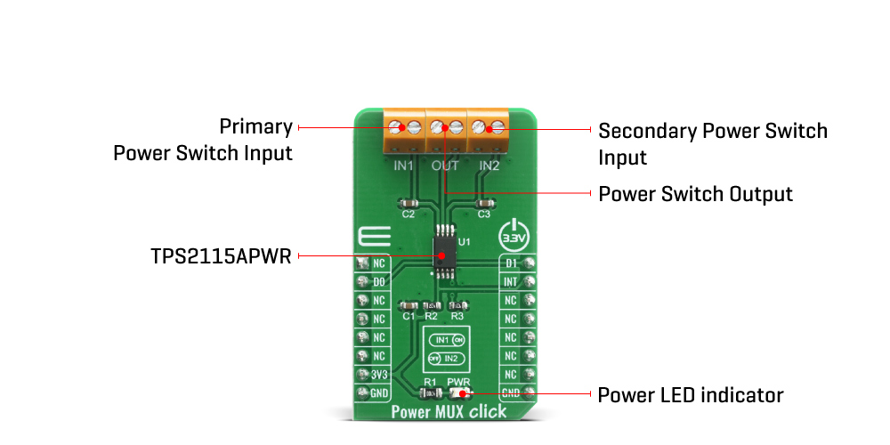
The Power MUX Click Board™ uses the TPS2115APWR IC, auto-switching power multiplexer that enables transition between two power supplies each operating at 2.8V to 5.5V voltage that comes from Texas Instruments. The Power MUX Click Board™ has two power switch inputs: primary and secondary. The IN1 switch can be enabled only if the IN1 supply is above the UVLO (under-voltage lockout) threshold and at least one supply exceeds the internal VDD UVLO, while the IN2 switch is enabled when the IN2 supply is above UVLO threshold and at least one supply exceeds the internal VDD UVLO.
In auto-switching mode pin D0 is equal to logic 1 and D1 pin is equal to logic 0 which means that this circuit will connect IN1 to OUT until the voltage at IN1 falls below a user-specified value. Once the voltage on IN1 falls below this value, the TPS2115APWR will select the higher of the two supplies. This usually means that the TPS2115APWR will swap to IN2. In manual switching mode pin D0 is equal to logic 0 and the multiplexer selects between two power supplies based upon the D1 logic signal. OUT connects to IN1 if D1 is logic 1; otherwise, OUT connects to IN2. The logic thresholds for the D1 terminal are compatible with both TTL and CMOS logic. There is also interrupt pin STAT that is Hi-Z if the IN2 switch is ON, while STAT goes low if the IN1 switch is ON or if OUT is Hi-Z. The under-voltage lockout circuit causes the output OUT to go Hi-Z if the selected power supply does not exceed the IN1/IN2 UVLO, or if neither of the supplies exceeds the internal VDD UVLO.
The switching circuitry ensures that both power switches will never conduct at the same time. A comparator monitors the gate-to-source voltage of each power FET and allows a FET to turn ON only if the gate-to-source voltage of the other FET is below the turn-on threshold voltage. When the TPS2115APWR switches from a higher voltage supply to a lower voltage supply, current can potentially flow back from the load capacitor into the lower voltage supply. To minimize such reverse conduction, the TPS2115APWR will not connect a supply to the output until the output voltage has fallen to within 100 mV of the supply voltage. Once supply has been connected to the output, it will remain connected regardless of the output voltage. This ensures reliable operation of the IC and the Click board™ itself.
The Power MUX Click Board™ does not use the power from the mikroBUS™ power rails, except 3.3V for the LED indicator, and interrupt's pull-up resistor. More information about the TPS2115APWR can be found in the attached datasheet. However, the Click board™ comes equipped with a library that contains easy to use functions and a usage example that may be used as a reference for the development.
| Type | Power Switch |
| Applications | The Power MUX Click Board™ can be used for the transition between two power supplies in applications such as PCs, PDAs, digital cameras, modems, digital radios, MP3 players, and similar applications. |
| On-board modules | The Power MUX Click Board™ uses the TPS2115APWR IC, auto-switching power multiplexer that enables transition between two power supplies each operating at 2.8V to 5.5V voltage that comes from Texas Instruments. |
| Key Features | Inrush current control, thermal protection, manual and auto-switching operating modes, cross-conduction blocking, reverse-conduction blocking |
| Interface | GPIO |
| Compatibility | mikroBUS |
| Click board size | M (42.9 x 25.4 mm) |
| Input Voltage | 3.3V |
This table shows how the pinout of the Power MUX Click Board™ corresponds to the pinout on the mikroBUS™ socket (the latter shown in the two middle columns).
| Notes | Pin | Pin | Notes | ||||
|---|---|---|---|---|---|---|---|
| NC | 1 | AN | PWM | 16 | D1 | Control pin 1 | |
| Control pin 0 | DO | 2 | RST | INT | 15 | INT | Switch Status |
| NC | 3 | CS | RX | 14 | NC | ||
| NC | 4 | SCK | TX | 13 | NC | ||
| NC | 5 | MISO | SCL | 12 | NC | ||
| NC | 6 | MOSI | SDA | 11 | NC | ||
| Power Supply | 3.3V | 7 | 3.3V | 5V | 10 | NC | |
| Ground | GND | 8 | GND | GND | 9 | GND | Ground |
| Label | Name | Default | Description |
|---|---|---|---|
| LD1 | PWR | - | Power LED Indicator |
| IN1 | TB1 | - | Primary Power Switch Input |
| IN2 | TB2 | - | Secondary Power Switch Input |
| OUT | TB3 | - | Power Switch Output |
| Description | Min | Typ | Max | Unit |
|---|---|---|---|---|
| Supply Voltage IN1, IN2 | -0.3 | - | +6 | V |
| Output Voltage | -0.3 | - | +6 | V |
| Maximum Output Current | - | - | 1.5 | A |
| Current limit adjustment range | 0.63 | - | 2 | A |
We provide a library for the Power MUX Click Board™ on our LibStock page, as well as a demo application (example), developed using MikroElektronika compilers. The demo can run on all the main MikroElektronika development boards.
The library covers all the necessary functions to control the Power MUX Click Board™. The Power MUX Click Board™ communicates with the target board through the RST, PWM and INT line. This library offers functions for setting D0 and D1 pins or to use predefined output from input channel 1, output from input channel 2, automatic output channel selection and disable output settings.
void powermux_output_input_ch_1 ( ); - Function is used to set output from input channel 1.void powermux_output_input_ch_2 ( ); - Function is used to set output from input channel 2.void powermux_auto_sel_input_ch ( ); - Function is used to set automatic output channel selection.The application is composed of three sections :
void application_task ( )
{
 mikrobus_logWrite( "No output", _LOG_LINE );
 powermux_no_output( );
 Delay_ms( 2000 );
 mikrobus_logWrite( "Output from input channel 1", _LOG_LINE );
 powermux_output_input_ch_1( );
 Delay_ms( 5000 );
 mikrobus_logWrite( "No output", _LOG_LINE );
 powermux_no_output( );
 Delay_ms( 2000 );
 mikrobus_logWrite( "Output from input channel 2", _LOG_LINE );
 powermux_output_input_ch_2( );
 Delay_ms( 5000 );
 mikrobus_logWrite( "No output", _LOG_LINE );
 powermux_no_output( );
 Delay_ms( 2000 );
 mikrobus_logWrite( "auto select output channel", _LOG_LINE );
 powermux_auto_sel_input_ch( );
 Delay_ms( 5000 );
}
The full application code, and ready to use projects can be found on our LibStock page.
Other mikroE Libraries used in the example:
Depending on the development board you are using, you may need USB UART Click Board™, USB UART 2 Click Board™ or RS232 Click Board™ to connect to your PC, for development systems with no UART to USB interface available on the board. The terminal available in all MikroElektronika compilers, or any other terminal application of your choice, can be used to read the message.
The Power MUX Click Board™ is supported with mikroSDK - MikroElektronika Software Development Kit. To ensure proper operation of mikroSDK compliant Click board™ demo applications, mikroSDK should be downloaded from the LibStock and installed for the compiler you are using.
- attachments: [{"download_file":[{"download_file":"Power MUX Click Board™ Schematic"}],"download_filetype":[{"download_filetype":"pdf"}]},{"download_file":[{"download_file":"Texas Instruments TPS2115A Power MUX Datasheet"}],"download_filetype":[{"download_filetype":"pdf"}]}] - device_vendor: Texas Instruments - device_type: TPS2115APWR - warranty: 12 months - brand: MikroE - key_feature_1: Power Switching Multiplexer - manufacturer: Mikroelektronika d.o.o. - target_keyword: Power MUX Click Board - brands: gid://shopify/Metaobject/56256004319 - breadcrumbs: ["gid://shopify/Collection/447955239135","gid://shopify/Collection/241680580797","gid://shopify/Collection/241545478333"] - customhs_code: 847330 - detailed_description: {"type":"root","children":[{"type":"heading","level":3,"children":[{"type":"text","value":"How Does The Power MUX Click Board™ Work?"}]},{"type":"paragraph","children":[{"type":"text","value":"The "},{"type":"text","value":"Power MUX Click Board™","bold":true},{"type":"text","value":" uses the TPS2115APWR IC, auto-switching power multiplexer that enables transition between two power supplies each operating at 2.8V to 5.5V voltage that comes from Texas Instruments. The "},{"type":"text","value":"Power MUX Click Board™","bold":true},{"type":"text","value":" has two power switch inputs: primary and secondary. The IN1 switch can be enabled only if the IN1 supply is above the UVLO (under-voltage lockout) threshold and at least one supply exceeds the internal VDD UVLO, while the IN2 switch is enabled when the IN2 supply is above UVLO threshold and at least one supply exceeds the internal VDD UVLO."}]},{"type":"paragraph","children":[{"type":"text","value":""}]},{"type":"paragraph","children":[{"type":"text","value":"In auto-switching mode pin D0 is equal to logic 1 and D1 pin is equal to logic 0 which means that this circuit will connect IN1 to OUT until the voltage at IN1 falls below a user-specified value. Once the voltage on IN1 falls below this value, the TPS2115APWR will select the higher of the two supplies. This usually means that the TPS2115APWR will swap to IN2. In manual switching mode pin D0 is equal to logic 0 and the multiplexer selects between two power supplies based upon the D1 logic signal. OUT connects to IN1 if D1 is logic 1; otherwise, OUT connects to IN2. The logic thresholds for the D1 terminal are compatible with both TTL and CMOS logic. There is also interrupt pin STAT that is Hi-Z if the IN2 switch is ON, while STAT goes low if the IN1 switch is ON or if OUT is Hi-Z. The under-voltage lockout circuit causes the output OUT to go Hi-Z if the selected power supply does not exceed the IN1/IN2 UVLO, or if neither of the supplies exceeds the internal VDD UVLO."}]},{"type":"paragraph","children":[{"type":"text","value":"The switching circuitry ensures that both power switches will never conduct at the same time. A comparator monitors the gate-to-source voltage of each power FET and allows a FET to turn ON only if the gate-to-source voltage of the other FET is below the turn-on threshold voltage. When the TPS2115APWR switches from a higher voltage supply to a lower voltage supply, current can potentially flow back from the load capacitor into the lower voltage supply. To minimize such reverse conduction, the TPS2115APWR will not connect a supply to the output until the output voltage has fallen to within 100 mV of the supply voltage. Once supply has been connected to the output, it will remain connected regardless of the output voltage. This ensures reliable operation of the IC and the Click board™ itself."}]},{"type":"paragraph","children":[{"type":"text","value":"The "},{"type":"text","value":"Power MUX Click Board™","bold":true},{"type":"text","value":" does not use the power from the mikroBUS™ power rails, except 3.3V for the LED indicator, and interrupt's pull-up resistor. More information about the TPS2115APWR can be found in the attached datasheet. However, the Click board™ comes equipped with a library that contains easy to use functions and a usage example that may be used as a reference for the development."}]},{"type":"heading","level":3,"children":[{"type":"text","value":"SPECIFICATIONS"}]},{"type":"paragraph","children":[{"type":"text","value":"Type\nPower Switch\nApplications\nThe Power MUX Click Board™ can be used for the transition between two power supplies in applications such as PCs, PDAs, digital cameras, modems, digital radios, MP3 players, and similar applications.\nOn-board modules\nThe Power MUX Click Board™ uses the TPS2115APWR IC, auto-switching power multiplexer that enables transition between two power supplies each operating at 2.8V to 5.5V voltage that comes from Texas Instruments.\nKey Features\nInrush current control, thermal protection, manual and auto-switching operating modes, cross-conduction blocking, reverse-conduction blocking\nInterface\nGPIO\nCompatibility\nmikroBUS\nClick board size\nM (42.9 x 25.4 mm)\nInput Voltage\n3.3V"}]},{"type":"heading","level":3,"children":[{"type":"text","value":"PINOUT DIAGRAM"}]},{"type":"paragraph","children":[{"type":"text","value":"This table shows how the pinout of the "},{"type":"text","value":"Power MUX Click Board™","bold":true},{"type":"text","value":" corresponds to the pinout on the mikroBUS™ socket (the latter shown in the two middle columns)."}]},{"type":"paragraph","children":[{"type":"text","value":"Notes\nPin\nPin\nNotes\nNC\n1\nAN\nPWM\n16\nD1\nControl pin 1\nControl pin 0\nDO\n2\nRST\nINT\n15\nINT\nSwitch Status\nNC\n3\nCS\nRX\n14\nNC\nNC\n4\nSCK\nTX\n13\nNC\nNC\n5\nMISO\nSCL\n12\nNC\nNC\n6\nMOSI\nSDA\n11\nNC\nPower Supply\n3.3V\n7\n3.3V\n5V\n10\nNC\nGround\nGND\n8\nGND\nGND\n9\nGND\nGround"}]},{"type":"heading","level":3,"children":[{"type":"text","value":"ONBOARD SETTINGS AND INDICATORS"}]},{"type":"paragraph","children":[{"type":"text","value":"Label\nName\nDefault\nDescription\nLD1\nPWR\n-\nPower LED Indicator\nIN1\nTB1\n-\nPrimary Power Switch Input\nIN2\nTB2\n-\nSecondary Power Switch Input\nOUT\nTB3\n-\nPower Switch Output"}]},{"type":"heading","level":3,"children":[{"type":"text","value":"POWER MUX CLICK ELECTRICAL SPECIFICATIONS"}]},{"type":"paragraph","children":[{"type":"text","value":"Description\nMin\nTyp\nMax\nUnit\nSupply Voltage IN1, IN2\n-0.3\n-\n+6\nV\nOutput Voltage\n-0.3\n-\n+6\nV\nMaximum Output Current\n-\n-\n1.5\nA\nCurrent limit adjustment range\n0.63\n-\n2\nA"}]},{"type":"heading","level":3,"children":[{"type":"text","value":" "}]}]} - summary:The Power MUX Click Board™ features power multiplexer that enables transition between two power supplies (such as a battery and a wall adapter), each operating at 2.8V to 5.5V and delivering up to 2A current depending on the package. This IC provides inrush current control and thermal protection to the Power MUX Click Board™, manual and auto-switching operating modes, cross-conduction blocking, and reverse-conduction blocking. Operating mode selection depends on a logic level on D0 and D1 pins. Power MUX Click can be used for the transition between two power supplies in applications such as PCs, PDAs, digital cameras, modems, digital radios, MP3 players, and similar applications.
The Power MUX Click Board™ is supported by a mikroSDK compliant library, which includes functions that simplify software development. This Click Board™ comes as a fully tested product, ready to be used on a system equipped with the mikroBUS™ socket.