# Title: AD-SWIO Click Board™
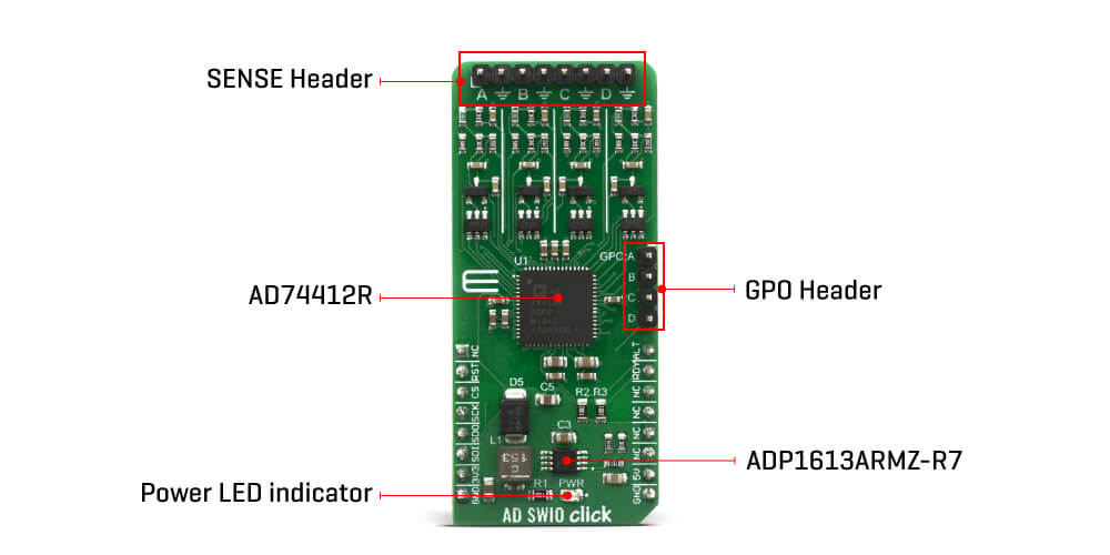
## Description: How Does The AD-SWIO Click Board™ Work? The AD-SWIO Click Board™ features a 16-bit analog-to-digital converter (ADC), and 13-bit digital-to-analog converter (DAC) embed in AD74412R from Analog Devices. There are several modes related to the AD74412R. These modes are voltage output, current output, voltage input, externally powered current input, loop powered current input, external RTD measurement, digital input logic, and loop powered digital input. The ADC can measure either the voltage across the 100 Ω RSENSE or the voltage at the I/OP_x screw terminal of each channel. In high impedance mode, the ADC, by default, measures the voltage across the screw terminals (I/OP_x to I/ON_x) in a 0 V to 10 V range. The ADC also provides diagnostic information on user-selectable inputs such as supplies, internal die temperature, reference, and regulators. The AD-SWIO Click Board™ has four GPO-x pins, one per channel ( GPO-A, GPO-B, GPO-C, GPO-D). Each channel GPO-x pin can be configured to the logic outputs of the digital input functions or a logic high or low output. The GPO-x pins can be set via the GPO_SELECT bits within the GPO_CONFIGx registers. The Click Board™ also contains LVIN ( Low Voltage Input) pin, the measurement voltage range on this pin is 0V to 2.5V. The AD74412R contains four 13-bit DACs, one per channel. Each DAC core is a 13-bit string DAC. The architecture structure consists of a string of resistors, each with a value of R. The digital input code that is loaded to the DAC_CODEx registers determines which node on the string the voltage is tapped off from and fed into the output amplifier. This architecture is inherently monotonic and linear. The AD74412R have short-circuit limit in voltage output mode is programmable per channel. The circuit minimizes glitching on the I/OP_x screw terminal when the AVDD supply is ramping or when the use case configuration is changed. This short-circuit limit, you can regulate with positive analog supply on AVDD pin, Output voltage on AD-SWIO Click Board™ is limited to +20V. The AD-SWIO Click Board™ is equipped with the ADP1613 step-up dc-to-dc switching converters with an integrated power switch capable of providing an output voltage as high as 20 V also from Analog Devices. SPECIFICATIONS Type SWIO,ADC-DAC Applications Applications Its a perfect choice for Process control, Factory automation, Motor drives, Building control systems. On-board modules AD74412R a quad-channel SWIO and ADP1613 step-up dc-to-dc switching converter all from Analog Devices Key Features Optimized for 16-bit ADC (Analog-to-Digital Converter) and 13-bit DAC (Digital-to-Analog Converter). Interface GPIO,SPI Compatibility mikroBUS Click Board™ size L (57.15 x 25.4 mm) Input Voltage 3.3V,5V PINOUT DIAGRAM This table shows how the pinout on the AD-SWIO Click Board™ corresponds to the pinout on the mikroBUS socket (the latter shown in the two middle columns). Notes Pin Pin Notes NC 1 AN PWM 16 ALT Alert Status Reset RST 2 RST INT 15 RDY Ready to read SPI Chip Select CS 3 CS RX 14 NC SPI Clock SCK 4 SCK TX 13 NC SPI Data OUT SDO 5 MISO SCL 12 NC SPI Data IN SDI 6 MOSI SDA 11 NC Power Supply 3.3V 7 3.3V 5V 10 5V Power Supply Ground GND 8 GND GND 9 GND Ground ONBOARD SETTINGS AND INDICATORS Label Name Default Description LD1 PWR - Power LED Indicator
## Product type: Click Board
## Vendor: Mikroelektronika d.o.o.
## Tags: ADC-DAC, Click Board, MikroE, Mixed SIgnal
## Price range: 62.3 - 62.3 GBP
## Link: https://thedebugstore.com/products/mikroe-4081-ad-swio-click-board-uk
## Compare-at price range: 89.0 - 89.0 GBP
## Options
- Title: Default Title
## Collections
- [New Products](https://thedebugstore.com/a/llms/collections/new-products-debug-store)
- [Mikroelektronika d.o.o. (MikroE)](https://thedebugstore.com/a/llms/collections/mikroelektronika-catalogue-uk)
- [Mixed Signal Click Boards™](https://thedebugstore.com/a/llms/collections/mixed-signal-click-boards-catalogue-uk)
- [MikroE Click Boards™](https://thedebugstore.com/a/llms/collections/mikroe-click-boards-catalogue-uk)
- [ADC/DAC Click Boards™](https://thedebugstore.com/a/llms/collections/adc-dac-click-boards-catalogue)
- [Click Boards™ Summer Sale](https://thedebugstore.com/a/llms/collections/inventory-sale)
- [MikroE Sale](https://thedebugstore.com/a/llms/collections/mikroe-sale)
- [MIKROE Stock](https://thedebugstore.com/a/llms/collections/mikroe-products-in-stock-sale)
## Variants
- Default Title, SKU: MIKROE-4081, Available: yes, Inventory: 1
## Metafields
- full_description: How Does The AD-SWIO Click Board™ Work?
The AD-SWIO Click Board™ features a 16-bit analog-to-digital converter (ADC), and 13-bit digital-to-analog converter (DAC) embed in AD74412R from Analog Devices. There are several modes related to the AD74412R. These modes are voltage output, current output, voltage input, externally powered current input, loop powered current input, external RTD measurement, digital input logic, and loop powered digital input.
The ADC can measure either the voltage across the 100 Ω RSENSE or the voltage at the I/OP_x screw terminal of each channel. In high impedance mode, the ADC, by default, measures the voltage across the screw terminals (I/OP_x to I/ON_x) in a 0 V to 10 V range. The ADC also provides diagnostic information on user-selectable inputs such as supplies, internal die temperature, reference, and regulators.
The AD-SWIO Click Board™ has four GPO-x pins, one per channel ( GPO-A, GPO-B, GPO-C, GPO-D). Each channel GPO-x pin can be configured to the logic outputs of the digital input functions or a logic high or low output. The GPO-x pins can be set via the GPO_SELECT bits within the GPO_CONFIGx registers. The Click Board™ also contains LVIN ( Low Voltage Input) pin, the measurement voltage range on this pin is 0V to 2.5V.
The AD74412R contains four 13-bit DACs, one per channel. Each DAC core is a 13-bit string DAC. The architecture structure consists of a string of resistors, each with a value of R. The digital input code that is loaded to the DAC_CODEx registers determines which node on the string the voltage is tapped off from and fed into the output amplifier. This architecture is inherently monotonic and linear.
The AD74412R have short-circuit limit in voltage output mode is programmable per channel. The circuit minimizes glitching on the I/OP_x screw terminal when the AVDD supply is ramping or when the use case configuration is changed. This short-circuit limit, you can regulate with positive analog supply on AVDD pin, Output voltage on AD-SWIO Click Board™ is limited to +20V. The AD-SWIO Click Board™ is equipped with the ADP1613 step-up dc-to-dc switching converters with an integrated power switch capable of providing an output voltage as high as 20 V also from Analog Devices.
SPECIFICATIONS
| Type |
SWIO,ADC-DAC |
| Applications |
Applications Its a perfect choice for Process control, Factory automation, Motor drives, Building control systems. |
| On-board modules |
AD74412R a quad-channel SWIO and ADP1613 step-up dc-to-dc switching converter all from Analog Devices |
| Key Features |
Optimized for 16-bit ADC (Analog-to-Digital Converter) and 13-bit DAC (Digital-to-Analog Converter). |
| Interface |
GPIO,SPI |
| Compatibility |
mikroBUS |
| Click Board™ size |
L (57.15 x 25.4 mm) |
| Input Voltage |
3.3V,5V |
PINOUT DIAGRAM
This table shows how the pinout on the AD-SWIO Click Board™ corresponds to the pinout on the mikroBUS socket (the latter shown in the two middle columns).
| Notes |
Pin |
 |
Pin |
Notes |
| |
NC |
1 |
AN |
PWM |
16 |
ALT |
Alert Status |
| Reset |
RST |
2 |
RST |
INT |
15 |
RDY |
Ready to read |
| SPI Chip Select |
CS |
3 |
CS |
RX |
14 |
NC |
|
| SPI Clock |
SCK |
4 |
SCK |
TX |
13 |
NC |
|
| SPI Data OUT |
SDO |
5 |
MISO |
SCL |
12 |
NC |
|
| SPI Data IN |
SDI |
6 |
MOSI |
SDA |
11 |
NC |
|
| Power Supply |
3.3V |
7 |
3.3V |
5V |
10 |
5V |
Power Supply |
| Ground |
GND |
8 |
GND |
GND |
9 |
GND |
Ground |
ONBOARD SETTINGS AND INDICATORS
| Label |
Name |
Default |
Description |
| LD1 |
PWR |
- |
Power LED Indicator |
- description_tag: The AD-SWIO Click Board™ is a quad-channel software-configurable input/output solution based on AD74412R. The AD74412R is a quad-channel software-configurable input/output integrated circuit for building and process control applications. Available from Debug Store UK.
- title_tag: MikroE AD-SWIO Click Board™ (MIKROE-4081)
- manufacturer: Mikroelektronika d.o.o.
- warranty: 12 months
- amazon_enable: TRUE
- amazon_title: AD-SWIO Click Board
- amazon_product_type: computercomponent
- amazon_block: FALSE
- amazon_prime_enable: FALSE
- amazon_search: MikroElektronika Microelectronica MIKROE-1100
- amazon_uk_price: 43.12
- amazon_uk_currency: GBP
- amazon_de_currency: EUR
- amazon_de_price: 48.7256
- amazon_fr_currency: EUR
- amazon_fr_price: 48.7256
- amazon_es_currency: EUR
- amazon_es_price: 48.7256
- amazon_nl_currency: EUR
- amazon_nl_price: 48.7256
- amazon_it_currency: EUR
- amazon_it_price: 48.7256
- amazon_se_curency: SEK
- amazon_se_price: 491.568
- amazon_product_id: 8606018717262
- amazon_product_id_type: EAN
- amazon_update: Update
- amazon_short_description: The AD-SWIO Click Board™ is a quad-channel software configurable input/output solution based on AD74412R. The AD74412R is a quad-channel software configurable input/output integrated circuit for building and process control applications. The device provides a fully integrated single chip solution for input and output operation. The AD-SWIO Click Board™ contains four 13-bit DACs, one per chanal, and 16-bit Σ-∆ ADC. These options give a lot of flexibility in choosing functionality for analog output, analog input, digital input, resistance temperature detector (RTD), and thermocouple measurements integrated into a single chip solution with a serial peripheral interface (SPI).
- amazon_main_image: https://www.thedebugstore.com/images/product/lg-ad-swio-click-front.jpg
- amazon_other_image_1: https://www.thedebugstore.com/images/product/lg-ad-swio-click-back.jpg
- amazon_other_image_2: https://www.thedebugstore.com/images/product/lg-ad-swio-click-fusion.jpg
- amazon_other_image_3: https://www.thedebugstore.com/images/product/lg-ad-swio-click-shuttle.jpg
- amazon_other_image_4: https://www.thedebugstore.com/images/product/lg-ad-swio-click-clicker.jpg
- amazon_other_image_5: https://www.thedebugstore.com/images/product/lg-ad-swio-click-breadboard.jpg
- amazon_other_image_6: https://www.thedebugstore.com/images/product/lg-ad-swio-click-breadboard.jpg
- amazon_browse_node: 428655031
- mpn: MIKROE-4081
- backorder_label: If no stock shown above, check availability
- examples:
We provide a library for the AD-SWIO Click Board™ on our LibStock page, as well as a demo application (example), developed using MikroElektronika compilers. The demo can run on all the main MikroElektronika development boards.
Library Description
This library has ability to perform a full control of the AD-SWIO Click Board™. This Click Board™ can convert and measure voltage, current and resistance from 4 independent channels and 4 different diagnostics.
Key Functions
adsdio_err_t adsdio_enable_ch( uint8_t channel ) - This function allows user to enable the desired channel/channels.adsdio_err_t adsdio_set_ch_func( uint8_t channel, uint8_t ch_func ) - This function allows user to modify the functionality of the selected channel.adsdio_err_t adsdio_get_conv_results( uint8_t channel, uint16_t *data_out ) - This function allows user to get the converted results of the selected channel.
Example Description
The application is composed of three sections :
- System Initialization - Initializes all necessary peripherals and pins used for this Click Board™. Also initializes uart console module.
- Application Initialization - Performs a hardware reset of the Click Board™ and executes a default configuration which includes that channel A will be enabled to measure voltage input in the range from 0V to 10V, with 4k8 SPS sample rating. In this function also Silicon Revision ID will be checked.
- Application Task - (code snippet) - Waits until data from the enabled channel is ready and then reads results of conversion for channel A and if response is ok, prints the results on the uart console.
void application_task( )
{
    adsdio_rdy = adsdio_status_pin_ready( );

    while ( adsdio_rdy == 0 )
    {
        adsdio_rdy = adsdio_status_pin_ready( );
    }

    adsdio_err = adsdio_get_conv_results( _ADSDIO_SETUP_CONV_EN_CHA,
                                          &adsdio_ch_a );

    if ( adsdio_err == _ADSDIO_ERR_STATUS_OK )
    {
        adsdio_res = adsdio_ch_a;
        adsdio_res /= _ADSDIO_RANGE_RESOLUTION;
        adsdio_res *= _ADSDIO_RANGE_VOLT_MV;
        adsdio_ch_a = adsdio_res;

        WordToStr( adsdio_ch_a, adsdio_log );
        Ltrim( adsdio_log );

        mikrobus_logWrite( "* CH A converted result is ", _LOG_TEXT );
        mikrobus_logWrite( adsdio_log, _LOG_TEXT );
        mikrobus_logWrite( " mV", _LOG_LINE );
        Delay_ms( 100 );
    }
}
Additional Functions :
- Application Default Handler - Used to send error report messages from Click Board™ driver to initialized console module.
The full application code, and ready to use projects can be found on our LibStock page.
Other mikroE Libraries used in the example:
- Conversions
- C_String
- SPI
- UART
Additional Notes and Information
Depending on the development board you are using, you may need a USB UART Click Board™, USB UART 2 Click Board™ or RS232 Click Board™ to connect to your PC, for development systems with no UART to USB interface available on the board. The terminal available in all MikroElektronika compilers, or any other terminal application of your choice, can be used to read the message.
MIKROSDK
The AD-SWIO Click Board™ is supported with mikroSDK - MikroElektronika Software Development Kit. To ensure proper operation of mikroSDK compliant Click Board™ demo applications, mikroSDK should be downloaded from the LibStock and installed for the compiler you are using.
- google_product_category: 2082
- attachments: [{"download_file":[{"download_file":"AD-SWIO Click Board™ Schematic"}],"download_filetype":[{"download_filetype":"pdf"}]},{"download_file":[{"download_file":"Analog Devices AD74412R Configurable I/O Datasheet"}],"download_filetype":[{"download_filetype":"pdf"}]}]
- condition: new
- custom_product: false
- mpn: MIKROE-4081
- google_product_category: Electronics
- custom_label_0: Click Board
- device_vendor: Analog Devices Inc.
- device_type: AD74412R, ADP1613ARMZ-R7
- warranty: 12 months
- brand: MikroE
- manufacturer: Mikroelektronika d.o.o.
- badge: No reviews
- widget:
- target_keyword: AD-SWIO Click Board
- brands: gid://shopify/Metaobject/56256004319
- breadcrumbs: ["gid://shopify/Collection/447955239135","gid://shopify/Collection/241680580797","gid://shopify/Collection/241545314493"]
- customhs_code: 847330
- detailed_description: {"type":"root","children":[{"type":"heading","level":3,"children":[{"type":"text","value":"How Does The AD-SWIO Click Board™ Work?"}]},{"type":"paragraph","children":[{"type":"text","value":"The "},{"type":"text","value":"AD-SWIO Click Board™","bold":true},{"type":"text","value":" features a 16-bit analog-to-digital converter (ADC), and 13-bit digital-to-analog converter (DAC) embed in AD74412R from Analog Devices. There are several modes related to the AD74412R. These modes are voltage output, current output, voltage input, externally powered current input, loop powered current input, external RTD measurement, digital input logic, and loop powered digital input."}]},{"type":"paragraph","children":[{"type":"text","value":""}]},{"type":"paragraph","children":[{"type":"text","value":"The ADC can measure either the voltage across the 100 Ω RSENSE or the voltage at the I/OP_x screw terminal of each channel. In high impedance mode, the ADC, by default, measures the voltage across the screw terminals (I/OP_x to I/ON_x) in a 0 V to 10 V range. The ADC also provides diagnostic information on user-selectable inputs such as supplies, internal die temperature, reference, and regulators."}]},{"type":"paragraph","children":[{"type":"text","value":"The "},{"type":"text","value":"AD-SWIO Click Board™","bold":true},{"type":"text","value":" has four GPO-x pins, one per channel ( GPO-A, GPO-B, GPO-C, GPO-D). Each channel GPO-x pin can be configured to the logic outputs of the digital input functions or a logic high or low output. The GPO-x pins can be set via the GPO_SELECT bits within the GPO_CONFIGx registers. The Click Board™ also contains LVIN ( Low Voltage Input) pin, the measurement voltage range on this pin is 0V to 2.5V."}]},{"type":"paragraph","children":[{"type":"text","value":"The AD74412R contains four 13-bit DACs, one per channel. Each DAC core is a 13-bit string DAC. The architecture structure consists of a string of resistors, each with a value of R. The digital input code that is loaded to the DAC_CODEx registers determines which node on the string the voltage is tapped off from and fed into the output amplifier. This architecture is inherently monotonic and linear."}]},{"type":"paragraph","children":[{"type":"text","value":"The AD74412R have short-circuit limit in voltage output mode is programmable per channel. The circuit minimizes glitching on the I/OP_x screw terminal when the AVDD supply is ramping or when the use case configuration is changed. This short-circuit limit, you can regulate with positive analog supply on AVDD pin, Output voltage on AD-SWIO Click Board™ is limited to +20V. The AD-SWIO Click Board™ is equipped with the ADP1613 step-up dc-to-dc switching converters with an integrated power switch capable of providing an output voltage as high as 20 V also from Analog Devices."}]},{"type":"heading","level":3,"children":[{"type":"text","value":"SPECIFICATIONS"}]},{"type":"paragraph","children":[{"type":"text","value":"Type\nSWIO,ADC-DAC\nApplications\nApplications Its a perfect choice for Process control, Factory automation, Motor drives, Building control systems.\nOn-board modules\nAD74412R a quad-channel SWIO and ADP1613 step-up dc-to-dc switching converter all from Analog Devices\nKey Features\nOptimized for 16-bit ADC (Analog-to-Digital Converter) and 13-bit DAC (Digital-to-Analog Converter).\nInterface\nGPIO,SPI\nCompatibility\nmikroBUS\nClick Board™ size\nL (57.15 x 25.4 mm)\nInput Voltage\n3.3V,5V"}]},{"type":"paragraph","children":[{"type":"text","value":" "}]},{"type":"heading","level":3,"children":[{"type":"text","value":"PINOUT DIAGRAM"}]},{"type":"paragraph","children":[{"type":"text","value":"This table shows how the pinout on the "},{"type":"text","value":"AD-SWIO Click Board™","bold":true},{"type":"text","value":" corresponds to the pinout on the mikroBUS socket (the latter shown in the two middle columns)."}]},{"type":"paragraph","children":[{"type":"text","value":"Notes\nPin\nPin\nNotes\nNC\n1\nAN\nPWM\n16\nALT\nAlert Status\nReset\nRST\n2\nRST\nINT\n15\nRDY\nReady to read\nSPI Chip Select\nCS\n3\nCS\nRX\n14\nNC\nSPI Clock\nSCK\n4\nSCK\nTX\n13\nNC\nSPI Data OUT\nSDO\n5\nMISO\nSCL\n12\nNC\nSPI Data IN\nSDI\n6\nMOSI\nSDA\n11\nNC\nPower Supply\n3.3V\n7\n3.3V\n5V\n10\n5V\nPower Supply\nGround\nGND\n8\nGND\nGND\n9\nGND\nGround"}]},{"type":"heading","level":3,"children":[{"type":"text","value":""},{"type":"text","value":"ONBOARD SETTINGS AND INDICATORS"}]},{"type":"paragraph","children":[{"type":"text","value":"Label\nName\nDefault\n Description\nLD1\nPWR\n-\nPower LED Indicator"}]}]}
- summary: The AD-SWIO Click Board™ is a quad-channel software-configurable input/output solution based on AD74412R. The AD74412R is a quad-channel software-configurable input/output integrated circuit for building and process control applications. The device provides a fully integrated single-chip solution for input and output operation.
The AD-SWIO Click Board™ contains four 13-bit DACs, one per chanal, and 16-bit Σ-∆ ADC. These options give a lot of flexibility in choosing functionality for analogue output, analogue input, digital input, resistance temperature detector (RTD), and thermocouple measurements integrated into a single chip solution with a serial peripheral interface (SPI).