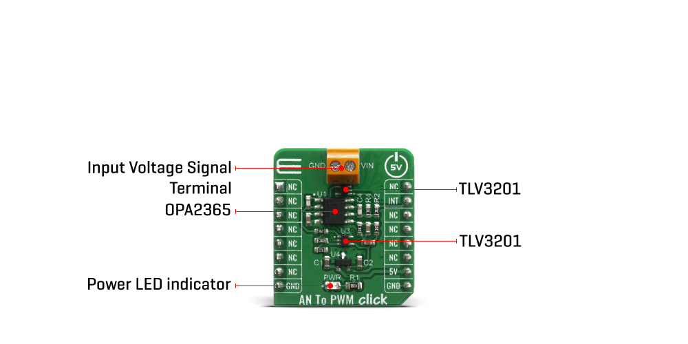
The AN to PWM Click Board™ is a device that converts an analog voltage input signal into a pulse width modulated (PWM) output signal. This Click Board™ consists of an analog circuitry, made of two comparators and two op-amps, needed for the described device. Op-amps used on this Click Board™ are OPA365 series, while comparators used are TLV 3201, both from Texas Instruments. It has a linear response, so applying a voltage in a range of -2.5 to 2.5V on its input, will result in generating the PWM pulse train with duty cycle linearly proportional to the input voltage.
This circuit on this Click Board™ utilizes a triangle wave generator and comparator to generate a pulse-width-modulated (PWM) waveform with a duty cycle that is inversely proportional to the input voltage. An op amp and comparator generate a triangular waveform which is passed to the inverting input of a second comparator. By passing the input voltage to the non-inverting comparator input, a PWM waveform is produced. Negative feedback of the PWM waveform to an error amplifier is utilized to ensure high accuracy and linearity of the output.
One op-amp (U1a) and one comparator (U3) are used in order to form the triangle wave generator. The error amplifier, composed of one op-amp U1b, serves two purposes. First, the error amplifier accommodates feedback of the output PWM waveform in order to correct for any errors in the output voltage introduced by the comparator on the output of the circuit (U2). Second, it adds a dc offset to the input voltage so that negative input voltages can be accommodated by the circuit. That way, in case that input signal is equal to 0V, the value of PWM duty cycle on the output is 50%.
The output PWM signal on the AN to PWM Click Board™ is brought to the INT pin of the mikroBUS socket, in order to enable fast and precise duty cycle measurement, using the interrupt routines. The frequency of the PWM signal is fixed to 500kHz.
The AN to PWM Click Board™ is designed to be operated only with 5V logic level. A proper logic voltage level conversion should be performed before the Click Board™ is used with MCUs with logic levels of 3.3V.
| Type | Measurements |
| Applications | AD conversion, inspection, test and measurement equipment, while it can also be used as the variable clock signal generator. |
| On-board modules | OPA2365 – Dual 50MHz, Low-Noise, Single-Supply Rail-to-Rail Operational Amplifier; TLV3201 - 40-ns, microPOWER, push-pull output comparator, both from Texas Instruments. |
| Key Features | Very good linearity, covers a positive and negative input voltage range and it has good temperature stability |
| Interface | GPIO |
| Compatibility | mikroBUS |
| Click Board™ size | S (28.6 x 25.4 mm) |
| Input Voltage | 5V |
This table shows how the pinout on the AN to PWM Click Board™ corresponds to the pinout on the mikroBUS socket (the latter shown in the two middle columns).
| Notes | Pin | Pin | Notes | ||||
|---|---|---|---|---|---|---|---|
| NC | 1 | AN | PWM | 16 | NC | ||
| NC | 2 | RST | INT | 15 | INT | PWM Output | |
| NC | 3 | CS | RX | 14 | NC | ||
| NC | 4 | SCK | TX | 13 | NC | ||
| NC | 5 | MISO | SCL | 12 | NC | ||
| NC | 6 | MOSI | SDA | 11 | NC | ||
| NC | 7 | 3.3V | 5V | 10 | 5V | Power Suppluy | |
| Ground | GND | 8 | GND | GND | 9 | GND | Ground |
| Label | Name | Default | Description |
|---|---|---|---|
| LD1 | PWR | - | Power LED Indicator |
We provide a library for the AN To PWM Click Board™ on our LibStock page, as well as a demo application (example), developed using MikroElektronika compilers. The demo can run on all the main MikroElektronika development boards.
The library contains a interrupt pin state function.
uint8_t antopwm_get_int_state( ) - Gets interrupt pin stateThe application is composed of three sections :
void application_task ( )
{
    uint8_t drdy;
    char rsp_data;

    drdy = UART_Rdy_Ptr( );

    if ( drdy != 0 )
    {
        rsp_data = UART_Rd_Ptr( );

        switch ( rsp_data )
        {
            case '+' :
            {
                // Reset flags
                period_flag = 0;
                idle_high_cnt = 0;
                idle_low_cnt = 0;
                period_cnt = 0;

                while ( period_flag != 1 );

                idle_high_cnt /= 10;
                idle_low_cnt /= 10;

                if ( ( idle_high_cnt != 0 ) && ( idle_high_cnt != 0 ) )
                {
                    tmp_value = calc_percentage( idle_high_cnt );
                    FloatToStr( tmp_value, demo_text );
                    mikrobus_logWrite( "> Idle [HIGH]: ~ ", _LOG_TEXT );
                    mikrobus_logWrite( demo_text, _LOG_TEXT );
                    mikrobus_logWrite( " %", _LOG_LINE );

                    tmp_value = calc_percentage( idle_low_cnt );
                    FloatToStr( tmp_value, demo_text );
                    mikrobus_logWrite( "> Idle [LOW]: ~ ", _LOG_TEXT );
                    mikrobus_logWrite( demo_text, _LOG_TEXT );
                    mikrobus_logWrite( " %", _LOG_LINE );

                    tmp_value = calc_voltage( idle_high_cnt );
                    FloatToStr( tmp_value , demo_text );
                    mikrobus_logWrite( "> Voltage: ~ ", _LOG_TEXT );
                    mikrobus_logWrite( demo_text, _LOG_TEXT );
                    mikrobus_logWrite( " mV", _LOG_LINE );

                    mikrobus_logWrite( "--------------------------------", _LOG_LINE );
                }
                mikrobus_logWrite( "--- Please, enter the command [ + ].", _LOG_LINE );
                break;
            }
        }
    }
}
Additional Functions :
The full application code, and ready to use projects can be found on our LibStock page.
Other mikroE Libraries used in the example:
Additional Notes and Fnformation
Depending on the development board you are using, you may need a USB UART Click Board™, USB UART 2 Click Board™ or RS232 Click Board™ to connect to your PC, for development systems with no UART to USB interface available on the board. The terminal available in all MikroElektronika compilers, or any other terminal application of your choice, can be used to read the message.
The AN to PWM Click Board™ is supported with mikroSDK - MikroElektronika Software Development Kit. To ensure proper operation of mikroSDK compliant Click Board™ demo applications, mikroSDK should be downloaded from the LibStock and installed for the compiler you are using.
- attachments: [{"download_file":[{"download_file":"AN to PWM Click Board™ Schematic"}],"download_filetype":[{"download_filetype":"pdf"}]},{"download_file":[{"download_file":"Texas Instruments OPA365 Operational Amplifier Datasheet"}],"download_filetype":[{"download_filetype":"pdf"}]},{"download_file":[{"download_file":"Texas Instruments TLV3201 Comparator Datasheet"}],"download_filetype":[{"download_filetype":"pdf"}]}] - condition: new - custom_product: false - mpn: MIKROE-4060 - google_product_category: Electronics - custom_label_0: Click Board - device_vendor: Texas Instruments - device_type: OPA2365AIDR, TLV3201AIDCKR - warranty: 12 months - brand: MikroE - manufacturer: Mikroelektronika d.o.o. - target_keyword: AN To PWM Click Board - brands: gid://shopify/Metaobject/56256004319 - breadcrumbs: ["gid://shopify/Collection/447955239135","gid://shopify/Collection/241680580797","gid://shopify/Collection/241545314493"] - customhs_code: 847330 - detailed_description: {"type":"root","children":[{"type":"heading","level":3,"children":[{"type":"text","value":"How Does The AN to PWM Click Board™ Work?"}]},{"type":"paragraph","children":[{"type":"text","value":"The "},{"type":"text","value":"AN to PWM Click Board™","bold":true},{"type":"text","value":" is a device that converts an analog voltage input signal into a pulse width modulated (PWM) output signal. This Click Board™ consists of an analog circuitry, made of two comparators and two op-amps, needed for the described device. Op-amps used on this Click Board™ are OPA365 series, while comparators used are TLV 3201, both from Texas Instruments. It has a linear response, so applying a voltage in a range of -2.5 to 2.5V on its input, will result in generating the PWM pulse train with duty cycle linearly proportional to the input voltage."}]},{"type":"paragraph","children":[{"type":"text","value":""}]},{"type":"paragraph","children":[{"type":"text","value":"This circuit on this Click Board™ utilizes a triangle wave generator and comparator to generate a pulse-width-modulated (PWM) waveform with a duty cycle that is inversely proportional to the input voltage. An op amp and comparator generate a triangular waveform which is passed to the inverting input of a second comparator. By passing the input voltage to the non-inverting comparator input, a PWM waveform is produced. Negative feedback of the PWM waveform to an error amplifier is utilized to ensure high accuracy and linearity of the output."}]},{"type":"paragraph","children":[{"type":"text","value":"One op-amp (U1a) and one comparator (U3) are used in order to form the triangle wave generator. The error amplifier, composed of one op-amp U1b, serves two purposes. First, the error amplifier accommodates feedback of the output PWM waveform in order to correct for any errors in the output voltage introduced by the comparator on the output of the circuit (U2). Second, it adds a dc offset to the input voltage so that negative input voltages can be accommodated by the circuit. That way, in case that input signal is equal to 0V, the value of PWM duty cycle on the output is 50%."}]},{"type":"paragraph","children":[{"type":"text","value":"The output PWM signal on the AN to PWM Click Board™ is brought to the INT pin of the mikroBUS socket, in order to enable fast and precise duty cycle measurement, using the interrupt routines. The frequency of the PWM signal is fixed to 500kHz."}]},{"type":"paragraph","children":[{"type":"text","value":"The "},{"type":"text","value":"AN to PWM Click Board™","bold":true},{"type":"text","value":" is designed to be operated only with 5V logic level. A proper logic voltage level conversion should be performed before the Click Board™ is used with MCUs with logic levels of 3.3V."}]},{"type":"heading","level":3,"children":[{"type":"text","value":"SPECIFICATIONS"}]},{"type":"paragraph","children":[{"type":"text","value":"Type\nMeasurements\nApplications\nAD conversion, inspection, test and measurement equipment, while it can also be used as the variable clock signal generator.\nOn-board modules\nOPA2365 – Dual 50MHz, Low-Noise, Single-Supply Rail-to-Rail Operational Amplifier; TLV3201 - 40-ns, microPOWER, push-pull output comparator, both from Texas Instruments.\nKey Features\nVery good linearity, covers a positive and negative input voltage range and it has good temperature stability\nInterface\nGPIO\nCompatibility\nmikroBUS\nClick Board™ size\nS (28.6 x 25.4 mm)\nInput Voltage\n5V"}]},{"type":"heading","level":3,"children":[{"type":"text","value":"Pinout Diagram"}]},{"type":"paragraph","children":[{"type":"text","value":"This table shows how the pinout on the "},{"type":"text","value":"AN to PWM Click Board™","bold":true},{"type":"text","value":" corresponds to the pinout on the mikroBUS socket (the latter shown in the two middle columns)."}]},{"type":"paragraph","children":[{"type":"text","value":"Notes\nPin\nPin\nNotes\nNC\n1\nAN\nPWM\n16\nNC\nNC\n2\nRST\nINT\n15\nINT\nPWM Output\nNC\n3\nCS\nRX\n14\nNC\nNC\n4\nSCK\nTX\n13\nNC\nNC\n5\nMISO\nSCL\n12\nNC\nNC\n6\nMOSI\nSDA\n11\nNC\nNC\n7\n3.3V\n5V\n10\n5V\nPower Suppluy\nGround\nGND\n8\nGND\nGND\n9\nGND\nGround"}]},{"type":"heading","level":3,"children":[{"type":"text","value":""},{"type":"text","value":"ONBOARD SETTINGS AND INDICATORS"}]},{"type":"paragraph","children":[{"type":"text","value":"Label\nName\nDefault\n Description\nLD1\nPWR\n-\nPower LED Indicator"}]},{"type":"heading","level":3,"children":[{"type":"text","value":" "}]}]} - summary:The AN to PWM Click Board™ is a device that converts the value of the input analogue signal with virtually any wave shape to a fixed frequency PWM voltage output, with a duty cycle proportional to the input voltage. It has a linear response, and by applying a signal with the voltage between -2.5V to +2.5V on its input, the Click Board™ will generate a pulse width modulated (PWM) output voltage, with a duty cycle ranging from 0% to 100%.
The AN to PWM Click features very good linearity, covers a positive and negative input voltage range and it has good temperature stability. These features allow this device to be used in various voltage to frequency applications, such as AD conversion, inspection, test and measurement equipment, while it can also be used as the variable clock signal generator.