The I2C MUX Click Board™ is packed with the TCA9546A, a quad bidirectional translating switch controlled via the I2C bus. The SCL/SDA upstream pair fans out to four downstream pairs, or channels. Any individual SCn/SDn channel or combination of channels can be selected, determined by the contents of the programmable control register. An active-low reset (RESET) input allows the TCA9546A to recover from a situation in which one of the downstream I2C buses is stuck in a low state. Pulling RESET low resets the I2C state machine and causes all the channels to be deselected, as does the internal power-on reset function. The pass gates of the switches are constructed such that the VCC pin can be used to limit the maximum high voltage, which will be passed by the TCA9546A. This allows the use of different bus voltages on each pair, so that 1.8-V, 2.5-V, or 3.3-V parts can communicate with 5-V parts without any additional protection. The slave devices can be connected to four headers located on the top of the I2C MUX click.
The TCA9546A supports Standard-Mode (100 kHz) and Fast-Mode (400 kHz) operation. This way, the bus can be used to manage a single 8-bit control register in which the four least significant bits control the enabling and disabling of the 4 switch channels of I2C data flow. The I2C bus is for two-way two-line communication between different ICs or modules. The two lines are a serial data line (SDA) and a serial clock line (SCL). Both lines must be connected to a positive supply via a pullup resistor when connected to the output stages of a device. Data transfer can be initiated only when the bus is not busy. One data bit is transferred during each clock pulse. The data on the SDA line must remain stable during the high period of the clock pulse, as changes in the data line at this time are interpreted as control signals.
Applications of the TCA9546A contains an I2C (or SMBus) master device and up to four I2C slave devices. The downstream channels are ideally used to resolve the I2C slave address conflicts. For example, if four identical digital temperature sensors are needed in the application, one sensor can be connected at each channel: 0, 1, 2, and 3. When the temperature at a specific location needs to be read, the appropriate channel can be enabled and all other channels switched off, the data can be retrieved, and the I2C master can move on and read the next channel.
The I2C MUX Click Board™ can be supplied and interfaced with both 3.3V and 5V without the need for any external components. The onboard SMD jumper labelled as VCC SEL allows voltage selection for interfacing with both 3.3V and 5V microcontrollers.
| Type | I2C |
| Applications | Servers, Routers (telecom switching equipment), Factory automation, Products with I2C slave address conflicts (multiple, identical temp sensors) |
| On-board modules | The I2C MUX Click Board™ uses the TCA9546A IC, a quad bidirectional translating switch, from Texas Instruments |
| Key Features | Voltage translation between 1.8V, 2.5V, 3.3V, and 5V buses, hot insertion, 0 - 400 kHz clock frequency range |
| Interface | I2C |
| Compatibility | mikroBUS |
| Click board size | M (42.9 x 25.4 mm) |
| Input Voltage | 3.3V or 5V |
This table shows how the pinout of the I2C MUX Click Board™ corresponds to the pinout on the mikroBUS™ socket (the latter shown in the two middle columns).
| Notes | Pin | Pin | Notes | ||||
|---|---|---|---|---|---|---|---|
| NC | 1 | AN | PWM | 16 | NC | ||
| Reset | RST | 2 | RST | INT | 15 | NC | |
| NC | 3 | CS | RX | 14 | NC | ||
| NC | 4 | SCK | TX | 13 | NC | ||
| NC | 5 | MISO | SCL | 12 | SCL | I2C Clock | |
| NC | 6 | MOSI | SDA | 11 | SDA | I2C Data | |
| Power Supply | 3.3V | 7 | 3.3V | 5V | 10 | 5V | Power Supply |
| Ground | GND | 8 | GND | GND | 9 | GND | Ground |
| Label | Name | Default | Description |
|---|---|---|---|
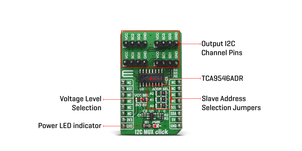
| LD1 | PWR | - | Power LED Indicator |
| JP1 | VCC SEL | Right | Power Supply Voltage Selection: left position 3V3, right position 5V |
| JP2-4 | ADD SEL | Right | Slave Address Selection: left position 1, right position 0 |
We provide a library for the I2C MUX Click Board™ on our LibStock page, as well as a demo application (example), developed using MikroElektronika compilers. The demo can run on all the main MikroElektronika development boards.
The library covers all the necessary functions to control the I2C MUX Click Board™ board.
void i2cmux_hw_reset ( void ) - Hardware reset function.void i2cmux_set_channel ( uint8_t channel, uint8_t ch_slave_address ) - Set channel function.void i2cmux_generic_read ( uint8_t reg, uint8_t *p_rx_data, uint8_t n_bytes ) - Generic read data function.The application is composed of three sections :
void application_task ( )
{
    // SET CHANNEL 0: 6DOF IMU 9 click
    i2cmux_set_channel( I2CMUX_CMD_SET_CH_0, 0x69 );
    Delay_ms( 100 );

    i2cmux_generic_read( 0x75, &rx_data, 1 );
    mikrobus_logWrite( " CH-0 : ID = 0x", _LOG_TEXT );
    display_log( );

    // SET CHANNEL 1: RTC 10 click
    i2cmux_set_channel( I2CMUX_CMD_SET_CH_1, 0x68 );
    Delay_ms( 100 );

    i2cmux_generic_read( 0x0F, &rx_data, 1 );
    mikrobus_logWrite( " CH-1 : ST = 0x", _LOG_TEXT );
    display_log( );

    // SET CHANNEL 2: Altitude click
    i2cmux_set_channel( I2CMUX_CMD_SET_CH_2, 0x60 );
    Delay_ms( 100 );

    i2cmux_generic_read( 0x0C, &rx_data, 1 );
    mikrobus_logWrite( " CH-2 : ID = 0x", _LOG_TEXT );
    display_log( );

    // SET CHANNEL 3: Temp & Hum click
    i2cmux_set_channel( I2CMUX_CMD_SET_CH_3, 0x5F );
    Delay_ms( 100 );

    i2cmux_generic_read( 0x0F, &rx_data, 1 );
    mikrobus_logWrite( " CH-3 : ID = 0x", _LOG_TEXT );
    display_log( );

    mikrobus_logWrite( "------------------", _LOG_LINE );
    Delay_ms( 2000 );
}
void display_log ( void ) - Display log function.The full application code, and ready to use projects can be found on our LibStock page.
Other mikroE Libraries used in the example:
Depending on the development board you are using, you may need USB UART click, USB UART 2 click or RS232 click to connect to your PC, for development systems with no UART to USB interface available on the board. The terminal available in all MikroElektronika compilers, or any other terminal application of your choice, can be used to read the message.
The I2C MUX Click Board™ is supported with mikroSDK - MikroElektronika Software Development Kit. To ensure proper operation of mikroSDK compliant Click board™ demo applications, mikroSDK should be downloaded from the LibStock and installed for the compiler you are using.
- attachments: [{"download_file":[{"download_file":"I2C MUX Click Board™ Schematic"}],"download_filetype":[{"download_filetype":"pdf"}]},{"download_file":[{"download_file":"Texas Instruments TCA9546A Quad Bidirectional Translating Switch Datasheet"}],"download_filetype":[{"download_filetype":"pdf"}],"download_filetype_ext":[{"download_filetype_ext":""}]}] - device_vendor: Texas Instruments - device_type: TCA9546ADR - warranty: 12 months - brand: MikroE - manufacturer: Mikroelektronika d.o.o. - target_keyword: I2C MUX Click Board - brands: gid://shopify/Metaobject/56256004319 - breadcrumbs: ["gid://shopify/Collection/447955239135","gid://shopify/Collection/241680580797","gid://shopify/Collection/241546100925"] - customhs_code: 847330 - detailed_description: {"type":"root","children":[{"type":"heading","level":3,"children":[{"type":"text","value":"How Does The I2C MUX Click Board™ Work?"}]},{"type":"paragraph","children":[{"type":"text","value":"The "},{"type":"text","value":"I2C MUX Click Board™","bold":true,"italic":true},{"type":"text","value":" is packed with the TCA9546A, a quad bidirectional translating switch controlled via the I2C bus. The SCL/SDA upstream pair fans out to four downstream pairs, or channels. Any individual SCn/SDn channel or combination of channels can be selected, determined by the contents of the programmable control register. An active-low reset (RESET) input allows the TCA9546A to recover from a situation in which one of the downstream I2C buses is stuck in a low state. Pulling RESET low resets the I2C state machine and causes all the channels to be deselected, as does the internal power-on reset function. The pass gates of the switches are constructed such that the VCC pin can be used to limit the maximum high voltage, which will be passed by the TCA9546A. This allows the use of different bus voltages on each pair, so that 1.8-V, 2.5-V, or 3.3-V parts can communicate with 5-V parts without any additional protection. The slave devices can be connected to four headers located on the top of the I2C MUX click."}]},{"type":"paragraph","children":[{"type":"text","value":""}]},{"type":"paragraph","children":[{"type":"text","value":"The TCA9546A supports Standard-Mode (100 kHz) and Fast-Mode (400 kHz) operation. This way, the bus can be used to manage a single 8-bit control register in which the four least significant bits control the enabling and disabling of the 4 switch channels of I2C data flow. The I2C bus is for two-way two-line communication between different ICs or modules. The two lines are a serial data line (SDA) and a serial clock line (SCL). Both lines must be connected to a positive supply via a pullup resistor when connected to the output stages of a device. Data transfer can be initiated only when the bus is not busy. One data bit is transferred during each clock pulse. The data on the SDA line must remain stable during the high period of the clock pulse, as changes in the data line at this time are interpreted as control signals."}]},{"type":"paragraph","children":[{"type":"text","value":"Applications of the TCA9546A contains an I2C (or SMBus) master device and up to four I2C slave devices. The downstream channels are ideally used to resolve the I2C slave address conflicts. For example, if four identical digital temperature sensors are needed in the application, one sensor can be connected at each channel: 0, 1, 2, and 3. When the temperature at a specific location needs to be read, the appropriate channel can be enabled and all other channels switched off, the data can be retrieved, and the I2C master can move on and read the next channel."}]},{"type":"paragraph","children":[{"type":"text","value":"The "},{"type":"text","value":"I2C MUX Click Board™","bold":true},{"type":"text","value":" can be supplied and interfaced with both 3.3V and 5V without the need for any external components. The onboard SMD jumper labelled as VCC SEL allows voltage selection for interfacing with both 3.3V and 5V microcontrollers."}]},{"type":"heading","level":3,"children":[{"type":"text","value":"SPECIFICATIONS"}]},{"type":"paragraph","children":[{"type":"text","value":"Type\nI2C\nApplications\nServers, Routers (telecom switching equipment), Factory automation, Products with I2C slave address conflicts (multiple, identical temp sensors)\nOn-board modules\nThe I2C MUX Click Board™ uses the TCA9546A IC, a quad bidirectional translating switch, from Texas Instruments\nKey Features\nVoltage translation between 1.8V, 2.5V, 3.3V, and 5V buses, hot insertion, 0 - 400 kHz clock frequency range\nInterface\nI2C\nCompatibility\nmikroBUS\nClick board size\nM (42.9 x 25.4 mm)\nInput Voltage\n3.3V or 5V"}]},{"type":"heading","level":3,"children":[{"type":"text","value":"PINOUT DIAGRAM"}]},{"type":"paragraph","children":[{"type":"text","value":"This table shows how the pinout of the "},{"type":"text","value":"I2C MUX Click Board™","bold":true},{"type":"text","value":" corresponds to the pinout on the mikroBUS™ socket (the latter shown in the two middle columns)."}]},{"type":"paragraph","children":[{"type":"text","value":"Notes\nPin\nPin\nNotes\nNC\n1\nAN\nPWM\n16\nNC\nReset\nRST\n2\nRST\nINT\n15\nNC\nNC\n3\nCS\nRX\n14\nNC\nNC\n4\nSCK\nTX\n13\nNC\nNC\n5\nMISO\nSCL\n12\nSCL\nI2C Clock\nNC\n6\nMOSI\nSDA\n11\nSDA\nI2C Data\nPower Supply\n3.3V\n7\n3.3V\n5V\n10\n5V\nPower Supply\nGround\nGND\n8\nGND\nGND\n9\nGND\nGround"}]},{"type":"heading","level":3,"children":[{"type":"text","value":"ONBOARD SETTINGS AND INDICATORS"}]},{"type":"paragraph","children":[{"type":"text","value":"Label\nName\nDefault\nDescription\nLD1\nPWR\n-\nPower LED Indicator\nJP1\nVCC SEL\nRight\nPower Supply Voltage Selection: left position 3V3, right position 5V\nJP2-4\nADD SEL\nRight\nSlave Address Selection: left position 1, right position 0"}]},{"type":"heading","level":3,"children":[{"type":"text","value":" "}]}]} - summary:The I2C MUX Click Board™ is a quad bidirectional translating I2C and SMBus switch with reset function, intended for applications with I2C slave address conflicts (multiple, identical temp sensors). It features a quad bidirectional translating switch controlled via the I2C bus, labelled as TCA9546A from Texas Instruments. Click Board™ has three address jumpers, allowing up to eight TCA9546A devices on the same bus.
The I2C MUX Click Board™ allows voltage translation between 1.8V, 2.5V, 3.3V, and 5V buses, and also supports hot insertion. The TCA9546A can work on a 0 - 400 kHz clock frequency range and is ideal for communication with numerous devices that share the identical slave address on the same bus.