# Title: RS232 SPI Click Board™
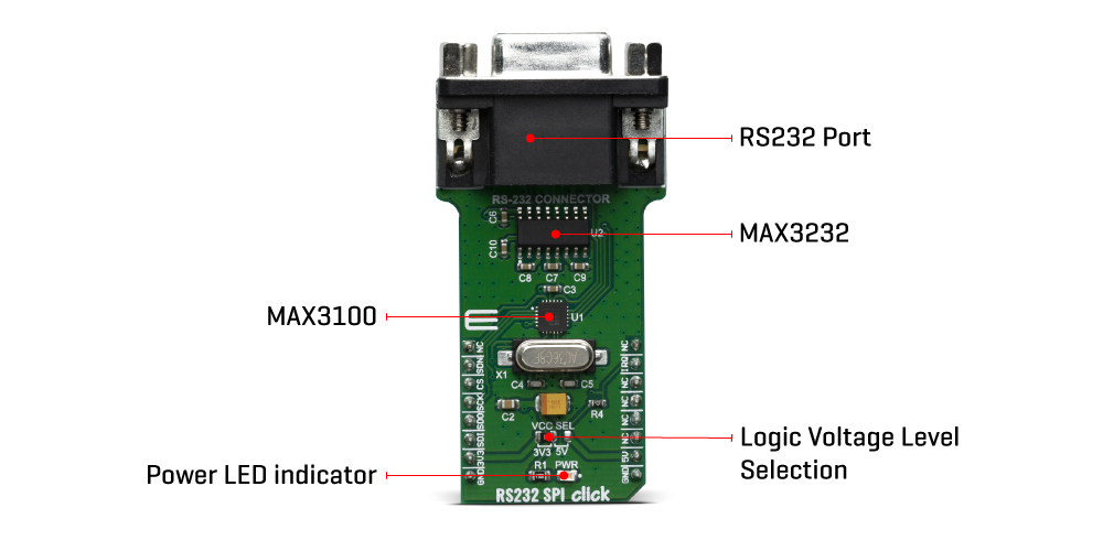
## Description: How Does The RS232 SPI Click Board™ Work? The RS232 SPI Click Board™ uses two ICs - MAX3100 and MAX3232. MAX3100 serves as UART interface to the SPI/MICROWIRE compatible interface converter. In the same time, MAX3232 device enables RS232 SPI click to meet the requirements of TIA/EIA-232-F and also provides the electrical interface between an asynchronous communication controller and the serial-port connector. The charge pump and four small external capacitors allow operation from a single 3-V to 5.5-V supply. The RS232 SPI Click Board™ Uses an SPI™/MICROWIRE™ interface for communication with the host microcontroller (µC). Then, the MAX3100 is responsible for conversion from synchronous serial data from a microcontroller to asynchronous, serial-data communication port such as RS-232, RS-485, IrDA. In this case the RS232 protocol is used. The MAX3100 includes a crystal oscillator and a baud rate generator with software-programmable divider ratios for all common baud rates from 300 baud to 230k baud. The transmitter section accepts SPI/MICROWIRE data, formats it, and transmits it in asynchronous serial format from the TX output. Data is loaded into the transmit buffer register from the SPI/MICROWIRE interface. The MAX3100 adds start and stop bits to the data and clocks the data out at the selected baud rate. A software- or hardware-invoked shutdown lowers quiescent current to 10µA, while allowing the MAX3100 to detect receiver activity. An 8-word-deep first-in/first-out (FIFO) buffer minimizes processor overhead. This device also includes a flexible interrupt with four maskable sources, including address recognition on 9-bit networks. Two hardware-handshaking control lines are included (one input and one output). Because of the features contained in its modules, the RS232 SPI click can be used for handheld instruments, UART in SPI systems, small networks in HVAC or Building control, battery-powered systems, PDAs, notebooks and many more. The RS232 SPI Click Board™ offers a selection between 3.3V and 5V operation, with the onboard SMD jumper, labelled as VCC SEL. This allows both 3.3V and 5V MCUs to be interfaced with this Click board™. SPECIFICATIONS Type RS232 Applications Handheld instruments, UART in SPI systems, small networks in HVAC or Building control, battery-powered systems, PDAs, notebooks and many more On-board modules MAX3100 MAX3100 serves as UART interface to the SPI/MICROWIRE compatible interface converter from Maxim Integrated; MAX3232, a 3-V to 5.5-V Multichannel RS-232 Line Driver/Receiver from Texas Instruments Key Features Operates up to 250 kbit/s, Operates With 3-V to 5.5-V VCC Supply, RS-232 Bus-Terminal ESD Protection Exceeds ±15 kV Using Human-Body Model (HBM) Interface SPI Compatibility mikroBUS Click board size L (57.15 x 25.4 mm) Input Voltage 3.3V or 5V PINOUT DIAGRAM This table shows how the pinout of the RS232 SPI Click Board™ corresponds to the pinout on the mikroBUS™ socket (the latter shown in the two middle columns). Notes Pin Pin Notes NC 1 AN PWM 16 NC Device shut down SDN 2 RST INT 15 INQ Interrupt Output SPI Chip Select CS 3 CS RX 14 NC SPI Clock SCK 4 SCK TX 13 NC SPI Data OUT SDO 5 MISO SCL 12 NC SPI Data IN SDI 6 MOSI SDA 11 NC Power Supply 3.3V 7 3.3V 5V 10 5V Power supply Ground GND 8 GND GND 9 GND Ground ONBOARD SETTINGS AND INDICATORS Label Name Default Description LD1 PWR LED - Power LED Indicator JP1 VCC SEL Left Power supply voltage selection: left position 3.3V, right position 5V
## Product type: Click Board
## Vendor: Mikroelektronika d.o.o.
## Tags: Analog Devices, Click Board, Interface, Maxim Integrated, MikroE, RS-232, Serial Interface
## Price range: 24.5 - 24.5 GBP
## Link: https://thedebugstore.com/products/mikroe-3912-rs232-spi-click-board-uk
## Compare-at price range: 35.0 - 35.0 GBP
## Options
- Title: Default Title
## Collections
- [New Products](https://thedebugstore.com/a/llms/collections/new-products-debug-store)
- [Mikroelektronika d.o.o. (MikroE)](https://thedebugstore.com/a/llms/collections/mikroelektronika-catalogue-uk)
- [Analog Devices Development Boards and Support Tools | Debug Store](https://thedebugstore.com/a/llms/collections/analog-devices-device-support-uk)
- [Maxim Integrated Device Support - Development Boards & Tools | Debug Store](https://thedebugstore.com/a/llms/collections/devices-maxim-integrated)
- [Serial Interface Click Boards™](https://thedebugstore.com/a/llms/collections/serial-interface-click-boards-catalogue)
- [MikroE Click Boards™](https://thedebugstore.com/a/llms/collections/mikroe-click-boards-catalogue-uk)
- [Interface Click Boards™](https://thedebugstore.com/a/llms/collections/interface-click-boards-catalogue)
- [RS-232 Interface Click Boards™](https://thedebugstore.com/a/llms/collections/rs-232-interface-click-boards-catalogue)
- [Click Boards™ Summer Sale](https://thedebugstore.com/a/llms/collections/inventory-sale)
- [MikroE Sale](https://thedebugstore.com/a/llms/collections/mikroe-sale)
- [MIKROE Stock](https://thedebugstore.com/a/llms/collections/mikroe-products-in-stock-sale)
## Variants
- Default Title, SKU: MIKROE-3912, Available: yes, Inventory: 1
## Metafields
- full_description: How Does The RS232 SPI Click Board™ Work?
The RS232 SPI Click Board™ uses two ICs - MAX3100 and MAX3232. MAX3100 serves as UART interface to the SPI/MICROWIRE compatible interface converter. In the same time, MAX3232 device enables RS232 SPI click to meet the requirements of TIA/EIA-232-F and also provides the electrical interface between an asynchronous communication controller and the serial-port connector. The charge pump and four small external capacitors allow operation from a single 3-V to 5.5-V supply.
The RS232 SPI Click Board™ Uses an SPI™/MICROWIRE™ interface for communication with the host microcontroller (µC). Then, the MAX3100 is responsible for conversion from synchronous serial data from a microcontroller to asynchronous, serial-data communication port such as RS-232, RS-485, IrDA. In this case the RS232 protocol is used. The MAX3100 includes a crystal oscillator and a baud rate generator with software-programmable divider ratios for all common baud rates from 300 baud to 230k baud. The transmitter section accepts SPI/MICROWIRE data, formats it, and transmits it in asynchronous serial format from the TX output. Data is loaded into the transmit buffer register from the SPI/MICROWIRE interface. The MAX3100 adds start and stop bits to the data and clocks the data out at the selected baud rate.
A software- or hardware-invoked shutdown lowers quiescent current to 10µA, while allowing the MAX3100 to detect receiver activity. An 8-word-deep first-in/first-out (FIFO) buffer minimizes processor overhead. This device also includes a flexible interrupt with four maskable sources, including address recognition on 9-bit networks. Two hardware-handshaking control lines are included (one input and one output).
Because of the features contained in its modules, the RS232 SPI click can be used for handheld instruments, UART in SPI systems, small networks in HVAC or Building control, battery-powered systems, PDAs, notebooks and many more.
The RS232 SPI Click Board™ offers a selection between 3.3V and 5V operation, with the onboard SMD jumper, labelled as VCC SEL. This allows both 3.3V and 5V MCUs to be interfaced with this Click board™.
SPECIFICATIONS
| Type |
RS232 |
| Applications |
Handheld instruments, UART in SPI systems, small networks in HVAC or Building control, battery-powered systems, PDAs, notebooks and many more |
| On-board modules |
MAX3100 MAX3100 serves as UART interface to the SPI/MICROWIRE compatible interface converter from Maxim Integrated; MAX3232, a 3-V to 5.5-V Multichannel RS-232 Line Driver/Receiver from Texas Instruments |
| Key Features |
Operates up to 250 kbit/s, Operates With 3-V to 5.5-V VCC Supply, RS-232 Bus-Terminal ESD Protection Exceeds ±15 kV Using Human-Body Model (HBM) |
| Interface |
SPI |
| Compatibility |
mikroBUS |
| Click board size |
L (57.15 x 25.4 mm) |
| Input Voltage |
3.3V or 5V |
PINOUT DIAGRAM
This table shows how the pinout of the RS232 SPI Click Board™ corresponds to the pinout on the mikroBUS™ socket (the latter shown in the two middle columns).
| Notes |
Pin |
 |
Pin |
Notes |
| NC |
1 |
AN |
PWM |
16 |
NC |
| Device shut down |
SDN |
2 |
RST |
INT |
15 |
INQ |
Interrupt Output |
| SPI Chip Select |
CS |
3 |
CS |
RX |
14 |
NC |
| SPI Clock |
SCK |
4 |
SCK |
TX |
13 |
NC |
| SPI Data OUT |
SDO |
5 |
MISO |
SCL |
12 |
NC |
| SPI Data IN |
SDI |
6 |
MOSI |
SDA |
11 |
NC |
| Power Supply |
3.3V |
7 |
3.3V |
5V |
10 |
5V |
Power supply |
| Ground |
GND |
8 |
GND |
GND |
9 |
GND |
Ground |
ONBOARD SETTINGS AND INDICATORS
| Label |
Name |
Default |
Description |
| LD1 |
PWR LED |
- |
Power LED Indicator |
| JP1 |
VCC SEL |
Left |
Power supply voltage selection: left position 3.3V, right position 5V |
- description_tag: The RS232 SPI Click Board™ is based around the MAX3100, a universal universal asynchronous receiver transmitter (UART) - the first UART specifically optimized for small microcontroller-based systems, from Maxim Integrated. Available from Debug Store UK.
- title_tag: MikroE RS232 SPI Click Board™ (MIKROE-3912)
- manufacturer: Mikroelektronika d.o.o.
- warranty: 12 months
- amazon_enable: TRUE
- amazon_title: RS232 SPI Click Board
- amazon_product_type: computercomponent
- amazon_block: FALSE
- amazon_prime_enable: FALSE
- amazon_search: MikroElektronika Microelectronica MIKROE-1100
- amazon_uk_price: 19.36
- amazon_uk_currency: GBP
- amazon_de_currency: EUR
- amazon_de_price: 21.8768
- amazon_fr_currency: EUR
- amazon_fr_price: 21.8768
- amazon_es_currency: EUR
- amazon_es_price: 21.8768
- amazon_nl_currency: EUR
- amazon_nl_price: 21.8768
- amazon_it_currency: EUR
- amazon_it_price: 21.8768
- amazon_se_curency: SEK
- amazon_se_price: 220.704
- amazon_product_id: 8606018719112
- amazon_product_id_type: EAN
- amazon_update: Update
- amazon_short_description: The RS232 SPI Click Board™ is based around the MAX3100, a universal universal asynchronous receiver transmitter (UART) - the first UART specifically optimized for small microcontroller-based systems, from Maxim Integrated. Because of the features contained in its modules, the RS232 SPI Click Board™ can be used for handheld instruments, small networks in HVAC or Building control, UART in SPI systems, battery-powered systems, PDAs, notebooks and many more.RS232 SPI Click Board™ is supported by a mikroSDK compliant library, which includes functions that simplify software development. This Click Board™ comes as a fully tested product, ready to be used on a system equipped with the mikroBUS™ socket.
- amazon_main_image: https://www.thedebugstore.com/images/product/lg-rs232-spi-click-back.jpg
- amazon_other_image_1: https://www.thedebugstore.com/images/product/lg-rs232-spi-click-front.jpg
- amazon_other_image_2: https://www.thedebugstore.com/images/product/lg-rs232-spi-click-fusion.jpg
- amazon_other_image_3: https://www.thedebugstore.com/images/product/lg-rs232-spi-click-shuttle.jpg
- amazon_other_image_4: https://www.thedebugstore.com/images/product/lg-rs232-spi-click-clicker.jpg
- amazon_other_image_5: https://www.thedebugstore.com/images/product/lg-rs232-spi-click-breadboard.jpg
- amazon_other_image_6: https://www.thedebugstore.com/images/product/lg-rs232-spi-click-breadboard.jpg
- amazon_browse_node: 428655031
- mpn: MIKROE-3912
- backorder_label: If no stock shown above, check availability
- google_product_category: 2082
- condition: new
- custom_product: false
- mpn: MIKROE-3912
- google_product_category: Electronics
- custom_label_0: Click Board
- examples:
We provide a library for the RS232 SPI Click Board™ on our LibStock page, as well as a demo application (example), developed using MikroElektronika compilers. The demo can run on all the main MikroElektronika development boards.
Library Description
The library covers all the necessary functions that enables the usage of the RS232 SPI Click Board™. User can send or receive data, check if data is ready or if tx line is busy, it is possible to change baud rate and to turn the device on or off.
Key Functions
uint8_t rs232spi_dataRead() - Function is used to read data from the receive register.uint16_t rs232spi_dataReady() - Function is used to check if there is availavle data for reading.void rs232spi_dataWrite( uint8_t wrData ) - Function is used to write into the transmit-buffer register.
Example Description
The application is composed of three sections :
- System Initialization - Initializes SPI and LOG structures, sets RST pin as output and INT pin as input.
- Application Initialization - Initialization driver enables SPI, sets up the device and starts write log.
- Application Task - (code snippet) This example demonstrates the use of RS232 SPI click board by sending or receiving the message.
void applicationTask()
{
    uint8_t tmp;
    char rec;
    uint8_t mode = RS232SPI_WRITE_MODE;

    if ( mode == RS232SPI_READ_MODE )
    {
        // RECEIVER - UART polling
        if ( rs232spi_dataReady() != 0 )
        {
            rec = rs232spi_transfer( _RS232SPI_CMD_READ_DATA );
            mikrobus_logWrite( &rec, _LOG_BYTE );
        }
    }
    else if ( mode == RS232SPI_WRITE_MODE )
    {
        // TRANSMITER - TX each 2 sec
        for ( tmp = 0; tmp < 9; tmp++ )
        {
            rs232spi_dataWrite( MESSAGE_DATA[ tmp ] );
            if ( tmp < 6 )
            {
                Delay_ms( 100 );
            }
        }
        Delay_ms( 2000 );
    }
}
The full application code, and ready to use projects can be found on our LibStock page.
Other mikroE Libraries used in the example:
Additional Notes and Information
Depending on the development board you are using, you may need USB UART click, USB UART 2 click or RS232 click to connect to your PC, for development systems with no UART to USB interface available on the board. The terminal available in all MikroElektronika compilers, or any other terminal application of your choice, can be used to read the message.
MIKROSDK
The RS232 SPI Click Board™ is supported with mikroSDK - MikroElektronika Software Development Kit. To ensure proper operation of mikroSDK compliant Click board™ demo applications, mikroSDK should be downloaded from the LibStock and installed for the compiler you are using.
- attachments: [{"download_file":[{"download_file":"RS232 SPI Click Board™ Schematic"}],"download_filetype":[{"download_filetype":"pdf"}]},{"download_file":[{"download_file":"Maxim MAX3100 SPI UART Datasheet"}],"download_filetype":[{"download_filetype":"pdf"}]},{"download_file":[{"download_file":"Maxim MAX3232 RS-232 Line Driver/Receiver Datasheet"}],"download_filetype":[{"download_filetype":"pdf"}]}]
- device_vendor: Maxim Integrated, Texas Instruments
- device_type: MAX3100ETG+, MAX3232IDRG4
- warranty: 12 months
- brand: MikroE
- manufacturer: Mikroelektronika d.o.o.
- badge: No reviews
- widget:
- brands: gid://shopify/Metaobject/56256004319
- breadcrumbs: ["gid://shopify/Collection/447955239135","gid://shopify/Collection/241680580797","gid://shopify/Collection/241546100925"]
- customhs_code: 847330
- detailed_description: {"type":"root","children":[{"type":"heading","level":3,"children":[{"type":"text","value":"How Does The RS232 SPI Click Board™ Work?"}]},{"type":"paragraph","children":[{"type":"text","value":"The"},{"type":"text","value":" RS232 SPI Click Board™","bold":true,"italic":true},{"type":"text","value":" uses two ICs - MAX3100 and MAX3232. MAX3100 serves as UART interface to the SPI/MICROWIRE compatible interface converter. In the same time, MAX3232 device enables RS232 SPI click to meet the requirements of TIA/EIA-232-F and also provides the electrical interface between an asynchronous communication controller and the serial-port connector. The charge pump and four small external capacitors allow operation from a single 3-V to 5.5-V supply."}]},{"type":"paragraph","children":[{"type":"text","value":""}]},{"type":"paragraph","children":[{"type":"text","value":"The "},{"type":"text","value":" RS232 SPI Click Board™","bold":true},{"type":"text","value":" Uses an SPI™/MICROWIRE™ interface for communication with the host microcontroller (µC). Then, the MAX3100 is responsible for conversion from synchronous serial data from a microcontroller to asynchronous, serial-data communication port such as RS-232, RS-485, IrDA. In this case the RS232 protocol is used. The MAX3100 includes a crystal oscillator and a baud rate generator with software-programmable divider ratios for all common baud rates from 300 baud to 230k baud. The transmitter section accepts SPI/MICROWIRE data, formats it, and transmits it in asynchronous serial format from the TX output. Data is loaded into the transmit buffer register from the SPI/MICROWIRE interface. The MAX3100 adds start and stop bits to the data and clocks the data out at the selected baud rate."}]},{"type":"paragraph","children":[{"type":"text","value":"A software- or hardware-invoked shutdown lowers quiescent current to 10µA, while allowing the MAX3100 to detect receiver activity. An 8-word-deep first-in/first-out (FIFO) buffer minimizes processor overhead. This device also includes a flexible interrupt with four maskable sources, including address recognition on 9-bit networks. Two hardware-handshaking control lines are included (one input and one output)."}]},{"type":"paragraph","children":[{"type":"text","value":"Because of the features contained in its modules, the RS232 SPI click can be used for handheld instruments, UART in SPI systems, small networks in HVAC or Building control, battery-powered systems, PDAs, notebooks and many more."}]},{"type":"paragraph","children":[{"type":"text","value":"The "},{"type":"text","value":" RS232 SPI Click Board™","bold":true},{"type":"text","value":" offers a selection between 3.3V and 5V operation, with the onboard SMD jumper, labelled as VCC SEL. This allows both 3.3V and 5V MCUs to be interfaced with this Click board™."}]},{"type":"heading","level":3,"children":[{"type":"text","value":"SPECIFICATIONS"}]},{"type":"paragraph","children":[{"type":"text","value":"Type\nRS232\nApplications\nHandheld instruments, UART in SPI systems, small networks in HVAC or Building control, battery-powered systems, PDAs, notebooks and many more\nOn-board modules\nMAX3100 MAX3100 serves as UART interface to the SPI/MICROWIRE compatible interface converter from Maxim Integrated; MAX3232, a 3-V to 5.5-V Multichannel RS-232 Line Driver/Receiver from Texas Instruments\nKey Features\nOperates up to 250 kbit/s, Operates With 3-V to 5.5-V VCC Supply, RS-232 Bus-Terminal ESD Protection Exceeds ±15 kV Using Human-Body Model (HBM)\nInterface\nSPI\nCompatibility\nmikroBUS\nClick board size\nL (57.15 x 25.4 mm)\nInput Voltage\n3.3V or 5V"}]},{"type":"heading","level":3,"children":[{"type":"text","value":"PINOUT DIAGRAM"}]},{"type":"paragraph","children":[{"type":"text","value":"This table shows how the pinout of the "},{"type":"text","value":" RS232 SPI Click Board™","bold":true},{"type":"text","value":" corresponds to the pinout on the mikroBUS™ socket (the latter shown in the two middle columns)."}]},{"type":"paragraph","children":[{"type":"text","value":"Notes\nPin\nPin\nNotes\nNC\n1\nAN\nPWM\n16\nNC\nDevice shut down\nSDN\n2\nRST\nINT\n15\nINQ\nInterrupt Output\nSPI Chip Select\nCS\n3\nCS\nRX\n14\nNC\nSPI Clock\nSCK\n4\nSCK\nTX\n13\nNC\nSPI Data OUT\nSDO\n5\nMISO\nSCL\n12\nNC\nSPI Data IN\nSDI\n6\nMOSI\nSDA\n11\nNC\nPower Supply\n3.3V\n7\n3.3V\n5V\n10\n5V\nPower supply\nGround\nGND\n8\nGND\nGND\n9\nGND\nGround"}]},{"type":"heading","level":3,"children":[{"type":"text","value":"ONBOARD SETTINGS AND INDICATORS"}]},{"type":"paragraph","children":[{"type":"text","value":"Label\nName\nDefault\nDescription\nLD1\nPWR LED\n-\nPower LED Indicator\nJP1\nVCC SEL\nLeft\nPower supply voltage selection: left position 3.3V, right position 5V"}]},{"type":"heading","level":3,"children":[{"type":"text","value":" "}]}]}
- summary: The RS232 SPI Click Board™ is based around the MAX3100, a universal asynchronous receiver transmitter (UART) - the first UART optimised explicitly for small microcontroller-based systems, from Maxim Integrated. Because of the features contained in its modules, the RS232 SPI Click Board™ can be used for handheld instruments, small networks in HVAC or Building control, UART in SPI systems, battery-powered systems, PDAs, notebooks and many more.
The RS232 SPI Click Board™ is supported by a mikroSDK compliant library, which includes functions that simplify software development. This Click Board™ comes as a thoroughly tested product, ready to be used on a system equipped with the mikroBUS™ socket.