# Title: WiFi 9 Click Board™
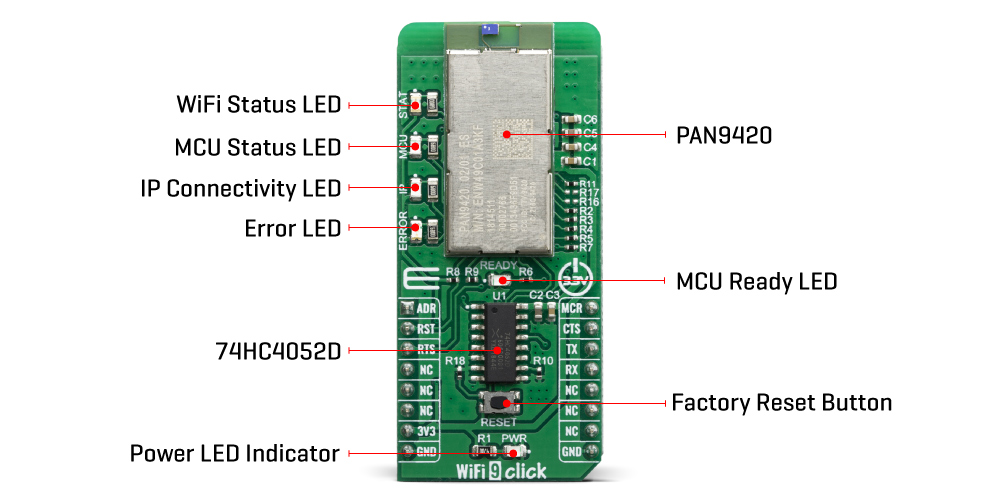
## Description: The WiFi 9 Click Board™ features the PAN9420 a 2.4 GHz 802.11 b/g/n embedded Wi-Fi module with integrated stack and API that minimizes firmware development and includes a full security suite. The module is specifically designed for highly integrated and cost-effective applications. The module includes a fully shielded case, integrated crystal oscillators, and a chip antenna. How Does The WiFi 9 Click Board™ Work? The WiFi 9 Click Board™ comes equipped with the PAN9420, a full embedded Wi-FI module from Panasonic. The module combines a high-performance CPU, high-sensitivity wireless radio, baseband processor, medium access controller, encryption unit, boot ROM with patching capability, internal SRAM, and in-system programmable flash memory. The module's integrated QSPI flash memory is available to the application for storing web content such as HTML pages or image data. Parallel support of access point and infrastructure mode allows easy setup of simultaneous Wi‑Fi connections from the module to smart devices and home network routers. The pre‑programmed Wi-Fi SoC firmware enables client (STA), micro access point (µAP), and Ad‑hoc mode (Wi-Fi Direct) applications. With the transparent mode, raw data can be sent from the UART to the air interface to smart devices, web servers, or PC applications. For working with PAN9420 module at your disposal are two data UART interfaces, one for command and another for transparent data. In order to enable simultaneous communication between the module and host MCU through one UART on mikroBUS™ socket we have added 74HC4052 multiplexer from Nexperia USA Inc. For selecting between UART0/UART1 you may use ADR pin (ADDRES): ADR pin state Module pins Selected Interface LOW TXD0/RXD0 UART0 HIGH TXD/RXD UART1 On the WiFi 9 Click Board™ several status LED's are implemented for easiest visual monitoring of the module states like MCU heartbeat, IP connectivity, Errors, WiFi connection and Booting. The PAN9420 supports Over-the-Air firmware updates. In order to make use of this feature, the customer needs to ensure that the appropriate preconditions are fulfilled and that a suitable environment is provided, particularly with regard to: Module configuration Utilization of the related module interface commands Server infrastructure and application The PAN9420 module is operated at 3.3V. Having in mind its absolute maximum ratings, it is not advisable to use the Click board™ with MCUs that use logic voltage levels up to 5V. SPECIFICATIONS Type WiFi Applications The WiFi 9 Click Board™ all necessary IoT functionality perfectly suited for IoT applications which require simultaneous support of Access-Point- and Infrastructure mode On-board modules Full featured standalone WiFi module PAN9420 from Panasonic, a 2.4 GHz ISM module which includes a wireless radio and an MCU Key Features Full-featured embedded network stack, integrated webserver, over-the-air firmware updates, integrated QSPI flash memory for customer web contents or configuration file storing Interface GPIO,UART Compatibility mikroBUS Click board size L (57.15 x 25.4 mm) Input Voltage 3.3V PINOUT DIAGRAM This table shows how the pinout of the WiFi 9 Click Board™ corresponds to the pinout on the mikroBUS™ socket (the latter shown in the two middle columns). Notes Pin Pin Notes Address Select ADR 1 AN PWM 16 MCU MCU Reset Reset RST 2 RST INT 15 CTS Clear to Send Request to Send RTS 3 CS RX 14 TX UART Transmit NC 4 SCK TX 13 RX UART Receive NC 5 MISO SCL 12 NC NC 6 MOSI SDA 11 NC Power Supply 3.3V 7 3.3V 5V 10 NC Ground GND 8 GND GND 9 GND Ground ONBOARD SETTINGS AND INDICATORS Label Name Default Description T1 RESET - Reset button for firmware rebooting LD1 MCU - MCU status (heartbeat) LED LD2 IP - IP connectivity (allocated IP) status LED LD3 ERROR - Error (active during booting) status LED LD4 STAT - Wireless (Wi-Fi) status LED LD5 READY - MCU ready (booting ready) status LED LED GREEN PWR - Power LED Indicator WIFI 9 CLICK LED STATUS LEGEND LED Application LED Function MCU OFF: Shut-off BLINK (1sec): Firmware active MCU status (heartbeat) IP OFF: no IP assigned ON: IP assigned IP connectivity in Infrastructure mode ERROR OFF: no error ON: error appeared MCU Firmware Error STAT OFF: no AP connection BLINK (0.2 s): Scanning for AP BLINK (0.4 s): trying to connect to AP BLINK (1.2 s): WLAN Error ON: Associated with AP WLAN connectivity in Infrastructure mode READY OFF: Shut-off ON: Firmware ready Firmware application is ready PWR ON: Click board is powered on OFF: Click boards is missing power Power LED Indicator
## Product type: Click Board
## Vendor: Mikroelektronika d.o.o.
## Tags: Click Board, MikroE, Panasonic, WiFi, Wireless
## Price range: 37.8 - 37.8 GBP
## Link: https://thedebugstore.com/products/mikroe-3666-wifi-9-click-board-uk
## Compare-at price range: 54.0 - 54.0 GBP
## Options
- Title: Default Title
## Collections
- [New Products](https://thedebugstore.com/a/llms/collections/new-products-debug-store)
- [Mikroelektronika d.o.o. (MikroE)](https://thedebugstore.com/a/llms/collections/mikroelektronika-catalogue-uk)
- [Panasonic Device Support Collection – Boards and Tools at Debug Store](https://thedebugstore.com/a/llms/collections/device-support-panasonic)
- [Wireless Interface Click Boards™](https://thedebugstore.com/a/llms/collections/wireless-interface-click-boards-catalogue)
- [MikroE Click Boards™](https://thedebugstore.com/a/llms/collections/mikroe-click-boards-catalogue-uk)
- [WiFi Click Boards™](https://thedebugstore.com/a/llms/collections/wifi-click-boards-catalogue)
- [Click Boards™ Summer Sale](https://thedebugstore.com/a/llms/collections/inventory-sale)
- [MikroE Sale](https://thedebugstore.com/a/llms/collections/mikroe-sale)
- [MIKROE Stock](https://thedebugstore.com/a/llms/collections/mikroe-products-in-stock-sale)
## Variants
- Default Title, SKU: MIKROE-3666, Available: yes, Inventory: 1
## Metafields
- full_description: The WiFi 9 Click Board™ features the PAN9420 a 2.4 GHz 802.11 b/g/n embedded Wi-Fi module with integrated stack and API that minimizes firmware development and includes a full security suite. The module is specifically designed for highly integrated and cost-effective applications. The module includes a fully shielded case, integrated crystal oscillators, and a chip antenna.
How Does The WiFi 9 Click Board™ Work?
The WiFi 9 Click Board™ comes equipped with the PAN9420, a full embedded Wi-FI module from Panasonic. The module combines a high-performance CPU, high-sensitivity wireless radio, baseband processor, medium access controller, encryption unit, boot ROM with patching capability, internal SRAM, and in-system programmable flash memory. The module's integrated QSPI flash memory is available to the application for storing web content such as HTML pages or image data.
Parallel support of access point and infrastructure mode allows easy setup of simultaneous Wi‑Fi connections from the module to smart devices and home network routers. The pre‑programmed Wi-Fi SoC firmware enables client (STA), micro access point (µAP), and Ad‑hoc mode (Wi-Fi Direct) applications. With the transparent mode, raw data can be sent from the UART to the air interface to smart devices, web servers, or PC applications.
For working with PAN9420 module at your disposal are two data UART interfaces, one for command and another for transparent data. In order to enable simultaneous communication between the module and host MCU through one UART on mikroBUS™ socket we have added 74HC4052 multiplexer from Nexperia USA Inc.
For selecting between UART0/UART1 you may use ADR pin (ADDRES):
| ADR pin state |
Module pins |
Selected Interface |
| LOW |
TXD0/RXD0 |
UART0 |
| HIGH |
TXD/RXD |
UART1 |
On the WiFi 9 Click Board™ several status LED's are implemented for easiest visual monitoring of the module states like MCU heartbeat, IP connectivity, Errors, WiFi connection and Booting.
The PAN9420 supports Over-the-Air firmware updates. In order to make use of this feature, the customer needs to ensure that the appropriate preconditions are fulfilled and that a suitable environment is provided, particularly with regard to:
- Module configuration
- Utilization of the related module interface commands
- Server infrastructure and application
The PAN9420 module is operated at 3.3V. Having in mind its absolute maximum ratings, it is not advisable to use the Click board™ with MCUs that use logic voltage levels up to 5V.
SPECIFICATIONS
| Type |
WiFi |
| Applications |
The WiFi 9 Click Board™ all necessary IoT functionality perfectly suited for IoT applications which require simultaneous support of Access-Point- and Infrastructure mode |
| On-board modules |
Full featured standalone WiFi module PAN9420 from Panasonic, a 2.4 GHz ISM module which includes a wireless radio and an MCU |
| Key Features |
Full-featured embedded network stack, integrated webserver, over-the-air firmware updates, integrated QSPI flash memory for customer web contents or configuration file storing |
| Interface |
GPIO,UART |
| Compatibility |
mikroBUS |
| Click board size |
L (57.15 x 25.4 mm) |
| Input Voltage |
3.3V |
PINOUT DIAGRAM
This table shows how the pinout of the WiFi 9 Click Board™ corresponds to the pinout on the mikroBUS™ socket (the latter shown in the two middle columns).
| Notes |
Pin |
 |
Pin |
Notes |
| Address Select |
ADR |
1 |
AN |
PWM |
16 |
MCU |
MCU Reset |
| Reset |
RST |
2 |
RST |
INT |
15 |
CTS |
Clear to Send |
| Request to Send |
RTS |
3 |
CS |
RX |
14 |
TX |
UART Transmit |
| NC |
4 |
SCK |
TX |
13 |
RX |
UART Receive |
| NC |
5 |
MISO |
SCL |
12 |
NC |
| NC |
6 |
MOSI |
SDA |
11 |
NC |
| Power Supply |
3.3V |
7 |
3.3V |
5V |
10 |
NC |
| Ground |
GND |
8 |
GND |
GND |
9 |
GND |
Ground |
ONBOARD SETTINGS AND INDICATORS
| Label |
Name |
Default |
Description |
| T1 |
RESET |
- |
Reset button for firmware rebooting |
| LD1 |
MCU |
- |
MCU status (heartbeat) LED |
| LD2 |
IP |
- |
IP connectivity (allocated IP) status LED |
| LD3 |
ERROR |
- |
Error (active during booting) status LED |
| LD4 |
STAT |
- |
Wireless (Wi-Fi) status LED |
| LD5 |
READY |
- |
MCU ready (booting ready) status LED |
| LED GREEN |
PWR |
- |
Power LED Indicator |
WIFI 9 CLICK LED STATUS LEGEND
| LED |
Application |
LED Function |
| MCU |
OFF: Shut-off
BLINK (1sec): Firmware active |
MCU status (heartbeat) |
| IP |
OFF: no IP assigned
ON: IP assigned |
IP connectivity in Infrastructure mode |
| ERROR |
OFF: no error
ON: error appeared |
MCU Firmware Error |
| STAT |
OFF: no AP connection
BLINK (0.2 s): Scanning for AP
BLINK (0.4 s): trying to connect to AP
BLINK (1.2 s): WLAN Error
ON: Associated with AP |
WLAN connectivity in
Infrastructure mode |
| READY |
OFF: Shut-off ON: Firmware ready |
Firmware application is ready |
| PWR |
ON: Click board is powered on
OFF: Click boards is missing power |
Power LED Indicator |
- description_tag: The WiFi 9 Click Board™ is a fully embedded stand-alone Wi-Fi module, equipped with the PAN9420 a 2.4 GHz ISM band WiFi-embedded module which includes a wireless radio and an MCU for easy integration of WiFi connectivity into various electronic devices. Available from Debug Store UK.
- title_tag: MikroE WiFi 9 Click Board™ (MIKROE-3666)
- manufacturer: Mikroelektronika d.o.o.
- warranty: 12 months
- amazon_enable: TRUE
- amazon_title: WiFi 9 Click Board
- amazon_product_type: computercomponent
- amazon_block: FALSE
- amazon_prime_enable: FALSE
- amazon_search: MikroElektronika Microelectronica MIKROE-1100
- amazon_uk_price: 39.6
- amazon_uk_currency: GBP
- amazon_de_currency: EUR
- amazon_de_price: 44.748
- amazon_fr_currency: EUR
- amazon_fr_price: 44.748
- amazon_es_currency: EUR
- amazon_es_price: 44.748
- amazon_nl_currency: EUR
- amazon_nl_price: 44.748
- amazon_it_currency: EUR
- amazon_it_price: 44.748
- amazon_se_curency: SEK
- amazon_se_price: 451.44
- amazon_product_id: 8606018716487
- amazon_product_id_type: EAN
- amazon_update: Update
- amazon_short_description: The WiFi 9 Click Board™ is fully embedded stand-alone Wi-Fi module, equipped with the PAN9420 a 2.4 GHz ISM band WiFi-embedded module which includes a wireless radio and an MCU for easy integration of WiFi connectivity into various electronic devices. This module combines a high-performance CPU with Wireless radio and integrated memory, which offers many features like webpage storing of HTML or image data, possibility to work in access point or infrastructure mode, and dual UART interface for communication with the host controllers.
- amazon_long_description: This board is featuring PAN9420 a 2.4 GHz 802.11 b/g/n embedded WiFi module with integrated stack and API that minimises firmware development and includes a full security suite. The module is specifically designed for highly integrated and cost-effective applications. The module includes a fully shielded case, integrated crystal oscillators, and a chip antenna.
How Does The WiFi 9 Click Board Work?
The WiFi 9 click comes equipped with the PAN9420, a full embedded Wi-FI module from Panasonic. The module combines a high-performance CPU, high-sensitivity wireless radio, baseband processor, medium access controller, encryption unit, boot ROM with patching capability, internal SRAM, and in-system programmable flash memory. The module’s integrated QSPI flash memory is available to the application for storing web content such as HTML pages or image data.

Parallel support of access point and infrastructure mode allows easy setup of simultaneous Wi‑Fi connections from the module to smart devices and home network routers. The pre‑programmed Wi-Fi SoC firmware enables client (STA), micro access point (µAP), and Ad‑hoc mode (Wi-Fi Direct) applications. With the transparent mode, raw data can be sent from the UART to the air interface to smart devices, web servers, or PC applications.
For working with PAN9420 module at your disposal are two data UART interfaces, one for command and another for transparent data. In order to enable simultaneous communication between the module and host MCU through one UART on mikroBUS™ socket we have added 74HC4052 multiplexer from Nexperia USA Inc.
For selecting between UART0/UART1 you may use ADR pin (ADDRES):
| ADR pin state | Module pins | Selected Interface |
|---|
| LOW | TXD0/RXD0 | UART0 |
| HIGH | TXD/RXD | UART1 |
On the WiFi 9 click board several status LED’s are implemented for easiest visual monitoring of the module states like MCU heartbeat, IP connectivity, Errors, WiFi connection and Booting.
The PAN9420 supports Over-the-Air firmware updates. In order to make use of this feature, the customer needs to ensure that the appropriate preconditions are fulfilled and that a suitable environment is provided, particularly with regard to:
- Module configuration
- Utilisation of the related module interface commands
- Server infrastructure and application
The PAN9420 module is operated at 3.3V. Having in mind its absolute maximum ratings, it is not advisable to use the Click board™ with MCUs that use logic voltage levels up to 5V.
- amazon_main_image: https://www.thedebugstore.com/images/product/lg-wifi-9-click-3666-front_1.jpg
- amazon_other_image_1: https://www.thedebugstore.com/images/product/lg-wifi-9-click-3666-back_1.jpg
- amazon_other_image_2: https://www.thedebugstore.com/images/product/lg-wifi-9-click-3666-in-use_1.jpg
- amazon_other_image_3: https://www.thedebugstore.com/images/product/lg-wifi-9-click-3666-in-use_1.jpg
- amazon_browse_node: 428655031
- mpn: MIKROE-3666
- backorder_label: If no stock shown above, check availability
- google_product_category: 285
- condition: new
- custom_product: false
- mpn: MIKROE-3666
- google_product_category: Electronics
- custom_label_0: Click Board
- examples:
We provide a library for the WiFi 9 Click Board™ on our LibStock page, as well as a demo application (example), developed using MikroElektronika compilers. The demo can run on all the main MikroElektronika development boards.
Library Description
Library carries generic command parser adopted for WiFi 9 command based modules.
Generic parser
Key Functions
wifi9_cmdSingle - Sends provided command to the module.wifi9_setHandler - Handler assignation to the provied command.wifi9_modulePower - Turn on module.
Example Description
The application is composed of three sections :
- System Initialization - Initializes all necessary GPIO pins, UART used for the communication with WIFI module and UART used for information logging.
- Application Initialization - Initializes driver, power on module and a procedure has been created with commands where the module connects to the WIFI router and opens the Netcat server.
- Application Task - running in parallel core state machine.
void applicationInit()
{

// TIMER INIT
 wifi9_configTimer();

// DRIVER INIT
 wifi9_uartDriverInit((T_WIFI9_P)&_MIKROBUS1_GPIO, (T_WIFI9_P)&_MIKROBUS1_UART);
 wifi9_coreInit( wifi9_default_handler, 1500 );

// MODULE POWER ON
 wifi9_hfcEnable( 0 );
 wifi9_modulePower( 1 );
 wifi9_selectUart(_WIFI9_SELECT_CMD_UART);
 Delay_ms( 4000 );
 mikrobus_logWrite( "---------------------", _LOG_LINE );
 mikrobus_logWrite( "---- System Info ----", _LOG_LINE );
 mikrobus_logWrite( "---------------------", _LOG_LINE );
 wifi9_cmdSingle(&_WIFI9_CMD_GET_SYSTEM_FIRMWARE[0]);
 Delay_ms( 500 );
 wifi9_cmdSingle(&_WIFI9_CMD_GET_SYSTEM_MAC_ADDR[0]);
 Delay_ms( 500 );
 wifi9_cmdSingle(&_WIFI9_CMD_GET_SYSTEM_SERIAL_NUM[0]);
 Delay_ms( 500 );
 wifi9_cmdSingle(&_WIFI9_CMD_GET_SYSTEM_RADIO_VER[0]);
 Delay_ms( 500 );
 wifi9_cmdSingle(&_WIFI9_CMD_GET_SYSTEM_BOOTL_VER[0]);
 Delay_ms( 500 );
 wifi9_cmdSingle(&_WIFI9_CMD_GET_SYSTEM_HW_REV[0]);
 Delay_ms( 5000 );
 mikrobus_logWrite( "--------------------------", _LOG_LINE );
 mikrobus_logWrite( "---- Start NETCAT app ----", _LOG_LINE );
 mikrobus_logWrite( "--------------------------", _LOG_LINE );
 mikrobus_logWrite( "> Reads the current Station status", _LOG_LINE );
 wifi9_cmdSingle(&_WIFI9_CMD_GET_WLAN_STATE_STA[0]);
 Delay_ms( 2000 );
 mikrobus_logWrite( "> Set Station to ON status", _LOG_LINE );
 wifi9_cmdSingle(&_WIFI9_CMD_SET_WLAN_STATE_STA_ON[0]);
 Delay_ms( 2000 );
 mikrobus_logWrite( "> Sets Station SSID and PASSWORD", _LOG_LINE );
 wifi9_cmdSingle(&_WIFI9_CMD_SET_WLAN_CFG_STA[0]);
 Delay_ms( 4000 );
 mikrobus_logWrite( "> Turn OFF - Netcat module", _LOG_LINE );
 wifi9_cmdSingle(&_WIFI9_CMD_SET_NETCAT_STATE_OFF[0]);
 Delay_ms( 2000 );
 mikrobus_logWrite( "> Turn ON - Netcat module", _LOG_LINE );
 wifi9_cmdSingle(&_WIFI9_CMD_SET_NETCAT_STATE_ON[0]);
 Delay_ms( 2000 );
 mikrobus_logWrite( "> Sets the Netcat module as a server with port 1234", _LOG_LINE );
 wifi9_cmdSingle(&_WIFI9_CMD_SET_NETCAT_CFG_SERVER[0]);
 Delay_ms( 2000 );
 mikrobus_logWrite( "> Excludes Netcat authentication", _LOG_LINE );
 wifi9_cmdSingle(&_WIFI9_CMD_SET_NETCAT_AUTH_OFF[0]);
 Delay_ms( 2000 );
 mikrobus_logWrite( "> Gets the current received IP address", _LOG_LINE );
 wifi9_cmdSingle(&_WIFI9_CMD_GET_NET_CFG_STA[0]);
 Delay_ms( 2000 );
 mikrobus_logWrite( "> At the moment, a netcat server at port 1234 has been built", _LOG_LINE );
 mikrobus_logWrite( "> The module is transferred to BIN-UART - for data collection", _LOG_LINE );
 wifi9_selectUart(_WIFI9_SELECT_BIN_UART);
 Delay_ms( 5000 );
}
Additional Functions :
All additional functions such as timer initialization and default handler.
Notes :
- First hold the reset button on the click board for about 5 seconds so that the module would perform a factory reset.
- When the module turns on and writes "factory reset" on the terminal.
- it's ready to be configured.
- In the example we've created a procedure that connects your module to WiFi network and sends commands for creating Netcat server with port (1234).
- After all commands are finished executing, it is necessary to create a Netcat client on a terminal (we used Cygwin64 terminal).
- In the example only some of the supported commands were used.
- the rest you can find in the technical documentation.
- Keep in mind that the click board uses two UART modules.
- CMD-UART(for sending commands) and BIN-UART(for sending the data)..
The full application code, and ready to use projects can be found on our LibStock page.
Other mikroE Libraries used in the example:
Additional Notes and Information
Depending on the development board you are using, you may need USB UART click, USB UART 2 click or RS232 click to connect to your PC, for development systems with no UART to USB interface available on the board. The terminal available in all MikroElektronika compilers, or any other terminal application of your choice, can be used to read the message.
MIKROSDK
The WiFi 9 Click Board™ is supported with mikroSDK - MikroElektronika Software Development Kit. To ensure proper operation of mikroSDK compliant Click board™ demo applications, mikroSDK should be downloaded from the LibStock and installed for the compiler you are using.
- attachments: [{"download_file":[{"download_file":"WiFi 9 Click Board™ Schematic"}],"download_filetype":[{"download_filetype":"pdf"}]},{"download_file":[{"download_file":"nexperia 74HC4052 4-Ch Multiplexer/Demultiplexer Datasheet"}],"download_filetype":[{"download_filetype":"pdf"}]}]
- device_vendor: Panasonic Electronic Components
- device_type: ENW-49C01A3KF
- warranty: 12 months
- brand: MikroE
- key_feature_1: 2.4 GHz ISM Band WiFi Interface
- manufacturer: Mikroelektronika d.o.o.
- badge: No reviews
- widget:
- target_keyword: WiFi 9 Click Board
- brands: gid://shopify/Metaobject/56256004319
- breadcrumbs: ["gid://shopify/Collection/447955239135","gid://shopify/Collection/241680580797","gid://shopify/Collection/241546166461"]
- customhs_code: 847330
- detailed_description: {"type":"root","children":[{"type":"paragraph","children":[{"type":"text","value":"The "},{"type":"text","value":"WiFi 9 Click Board™","bold":true},{"type":"text","value":" features the PAN9420 a 2.4 GHz 802.11 b/g/n embedded Wi-Fi module with integrated stack and API that minimizes firmware development and includes a full security suite. The module is specifically designed for highly integrated and cost-effective applications. The module includes a fully shielded case, integrated crystal oscillators, and a chip antenna."}]},{"type":"heading","level":3,"children":[{"type":"text","value":"How Does The WiFi 9 Click Board™ Work?"}]},{"type":"paragraph","children":[{"type":"text","value":"The "},{"type":"text","value":"WiFi 9 Click Board™","bold":true},{"type":"text","value":" comes equipped with the PAN9420, a full embedded Wi-FI module from Panasonic. The module combines a high-performance CPU, high-sensitivity wireless radio, baseband processor, medium access controller, encryption unit, boot ROM with patching capability, internal SRAM, and in-system programmable flash memory. The module's integrated QSPI flash memory is available to the application for storing web content such as HTML pages or image data."}]},{"type":"paragraph","children":[{"type":"text","value":""}]},{"type":"paragraph","children":[{"type":"text","value":"Parallel support of access point and infrastructure mode allows easy setup of simultaneous Wi‑Fi connections from the module to smart devices and home network routers. The pre‑programmed Wi-Fi SoC firmware enables client (STA), micro access point (µAP), and Ad‑hoc mode (Wi-Fi Direct) applications. With the transparent mode, raw data can be sent from the UART to the air interface to smart devices, web servers, or PC applications."}]},{"type":"paragraph","children":[{"type":"text","value":"For working with PAN9420 module at your disposal are two data UART interfaces, one for command and another for transparent data. In order to enable simultaneous communication between the module and host MCU through one UART on mikroBUS™ socket we have added 74HC4052 multiplexer from Nexperia USA Inc."}]},{"type":"paragraph","children":[{"type":"text","value":"For selecting between UART0/UART1 you may use ADR pin (ADDRES):"}]},{"type":"paragraph","children":[{"type":"text","value":"ADR pin state\nModule pins\nSelected Interface\nLOW\nTXD0/RXD0\nUART0\nHIGH\nTXD/RXD\nUART1"}]},{"type":"paragraph","children":[{"type":"text","value":"On the "},{"type":"text","value":"WiFi 9 Click Board™","bold":true},{"type":"text","value":" several status LED's are implemented for easiest visual monitoring of the module states like MCU heartbeat, IP connectivity, Errors, WiFi connection and Booting."}]},{"type":"paragraph","children":[{"type":"text","value":"The PAN9420 supports Over-the-Air firmware updates. In order to make use of this feature, the customer needs to ensure that the appropriate preconditions are fulfilled and that a suitable environment is provided, particularly with regard to:"}]},{"type":"list","listType":"unordered","children":[{"type":"list-item","children":[{"type":"text","value":"Module configuration"}]},{"type":"list-item","children":[{"type":"text","value":"Utilization of the related module interface commands"}]},{"type":"list-item","children":[{"type":"text","value":"Server infrastructure and application"}]}]},{"type":"paragraph","children":[{"type":"text","value":"The PAN9420 module is operated at 3.3V. Having in mind its absolute maximum ratings, it is not advisable to use the Click board™ with MCUs that use logic voltage levels up to 5V."}]},{"type":"heading","level":3,"children":[{"type":"text","value":"SPECIFICATIONS"}]},{"type":"paragraph","children":[{"type":"text","value":"Type\nWiFi\nApplications\nThe WiFi 9 Click Board™ all necessary IoT functionality perfectly suited for IoT applications which require simultaneous support of Access-Point- and Infrastructure mode\nOn-board modules\nFull featured standalone WiFi module PAN9420 from Panasonic, a 2.4 GHz ISM module which includes a wireless radio and an MCU\nKey Features\nFull-featured embedded network stack, integrated webserver, over-the-air firmware updates, integrated QSPI flash memory for customer web contents or configuration file storing\nInterface\nGPIO,UART\nCompatibility\nmikroBUS\nClick board size\nL (57.15 x 25.4 mm)\nInput Voltage\n3.3V"}]},{"type":"heading","level":3,"children":[{"type":"text","value":"PINOUT DIAGRAM"}]},{"type":"paragraph","children":[{"type":"text","value":"This table shows how the pinout of the "},{"type":"text","value":"WiFi 9 Click Board™","bold":true},{"type":"text","value":" corresponds to the pinout on the mikroBUS™ socket (the latter shown in the two middle columns)."}]},{"type":"paragraph","children":[{"type":"text","value":"Notes\nPin\nPin\nNotes\nAddress Select\nADR\n1\nAN\nPWM\n16\nMCU\nMCU Reset\nReset\nRST\n2\nRST\nINT\n15\nCTS\nClear to Send\nRequest to Send\nRTS\n3\nCS\nRX\n14\nTX\nUART Transmit\nNC\n4\nSCK\nTX\n13\nRX\nUART Receive\nNC\n5\nMISO\nSCL\n12\nNC\nNC\n6\nMOSI\nSDA\n11\nNC\nPower Supply\n3.3V\n7\n3.3V\n5V\n10\nNC\nGround\nGND\n8\nGND\nGND\n9\nGND\nGround"}]},{"type":"heading","level":3,"children":[{"type":"text","value":"ONBOARD SETTINGS AND INDICATORS"}]},{"type":"paragraph","children":[{"type":"text","value":"Label\nName\nDefault\nDescription\nT1\nRESET\n-\nReset button for firmware rebooting\nLD1\nMCU\n-\nMCU status (heartbeat) LED\nLD2\nIP\n-\nIP connectivity (allocated IP) status LED\nLD3\nERROR\n-\nError (active during booting) status LED\nLD4\nSTAT\n-\nWireless (Wi-Fi) status LED\nLD5\nREADY\n-\nMCU ready (booting ready) status LED\nLED GREEN\nPWR\n-\nPower LED Indicator"}]},{"type":"heading","level":3,"children":[{"type":"text","value":"WIFI 9 CLICK LED STATUS LEGEND"}]},{"type":"paragraph","children":[{"type":"text","value":"LED\nApplication\nLED Function\nMCU\nOFF: Shut-off\n BLINK (1sec): Firmware active\nMCU status (heartbeat)\nIP\nOFF: no IP assigned\n ON: IP assigned\nIP connectivity in Infrastructure mode\nERROR\nOFF: no error\n ON: error appeared\nMCU Firmware Error\nSTAT\nOFF: no AP connection\n BLINK (0.2 s): Scanning for AP\n BLINK (0.4 s): trying to connect to AP\n BLINK (1.2 s): WLAN Error\n ON: Associated with AP\nWLAN connectivity in\n Infrastructure mode\nREADY\nOFF: Shut-off ON: Firmware ready\nFirmware application is ready\nPWR\nON: Click board is powered on\n OFF: Click boards is missing power\nPower LED Indicator"}]},{"type":"heading","level":3,"children":[{"type":"text","value":" "}]}]}
- summary: The WiFi 9 Click Board™ is a fully embedded stand-alone Wi-Fi module, equipped with the PAN9420 a 2.4 GHz ISM band WiFi-embedded module which includes a wireless radio and an MCU for easy integration of WiFi connectivity into various electronic devices. This module combines a high-performance CPU with Wireless radio and integrated memory, which offers many features like webpage storing of HTML or image data, the possibility to work in the access point or infrastructure mode, and dual UART interface for communication with the host controllers.