# Title: Pedometer Click Board™
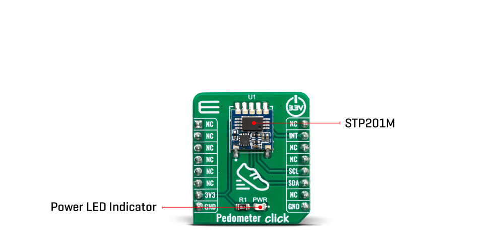
## Description: The Pedometer Click Board™ is designed to be fairly simple to use. This Click board™ contains the STP201M module, made by NiceRF. The module itself is designed for wrist pedometer products, like the pedometer bracelet or watch for example. The end user doesn't have to worry about doing any calculations on their own, or worry about what the algorithm for step detection is doing, since the INT pins output is already a measurement of the steps that were taken. Before that, though, come the intricate parts of the design inside. First of all, the STP201M module, which is the main component of the Pedometer Click Board™, has a built in G sensor within the IC chipset. How Does The Pedometer Click Board™ Work? Specifically, a MEMS sensor. Micro-electro-mechanical system sensors, abbreviated to MEMS, are made out of very small components, with their size usually ranging from 1 to 100 micrometers. These account for the sensor being very small and therefore it having low energy consumption and also not requiring a lot of space. This particular sensor is a 3D one. The three axes it utilizes, allow for precise measurements of any movement and the direction its taking. The three axes system, along with the MCUs meticulous algorithm, make it significantly less likely to make any false-positive counts (ex. tying up shoes). The MCU has two distinguished modes. The first one of them is the operational mode. The MCU is designed to go into the operational mode whenever it senses some activity. However, if there is no discernible movement over the course of 20 seconds, it goes into the sleep mode. This mode is characterized by the very low energy consumption of only 5 μA max. The STP201M modules communication is somewhat different from the standard I2C protocol. Since our libraries do not support it, the user has the capability of changing the code of the main MCU in order to fit the protocol of the module and thus change any preprogramed settings. Since the modules maximum operatin voltage is 3.6V, the Pedometer click uses the 3.3V rail for power supply. The other pins it utilizes are the, before mentioned, Interrupt pin, and the I2C Clock and Data pins. This click also has a Power LED indicator. The Pedometer Click Board™ is designed to be operated only with 3.3V logic level. A proper logic voltage level conversion should be performed before the Click board™ is used with MCUs with logic levels of 5V. SPECIFICATIONS Type Acceleration,Motion Applications The Pedometer Click Board™ can be used for tracking physical activity, for example measuring how many calories somebody burned and because of it's small size, it can be used in various healthcare products. On-board modules STP201M module, a 3D pedometer module with a precise G-sensor and MCU Key Features 3D MEMS sensor combined with high precision 3D pedometer algorithm gives a precisely pedometer in any direction. Interface I2C Compatibility mikroBUS Click board size S (28.6 x 25.4 mm) Input Voltage 3.3V PINOUT DIAGRAM This table shows how the pinout of the Pedometer Click Board™ corresponds to the pinout on the mikroBUS™ socket (the latter shown in the two middle columns). Notes Pin Pin Notes NC 1 AN PWM 16 NC NC 2 RST INT 15 INT Interrupt NC 3 CS RX 14 NC NC 4 SCK TX 13 NC NC 5 MISO SCL 12 SCL I2C Clock NC 6 MOSI SDA 11 SDA I2C Data Power Supply 3.3V 7 3.3V 5V 10 NC Ground GND 8 GND GND 9 GND Ground ONBOARD SETTINGS AND INDICATORS Label Name Default Description LD1 PWR - Power LED Indicator
## Product type: Click Board
## Vendor: Mikroelektronika d.o.o.
## Tags: Click Board, G-NiceRF, MikroE, Motion, Sensor
## Price range: 19.6 - 19.6 GBP
## Link: https://thedebugstore.com/products/mikroe-3567-pedometer-click-board-uk
## Compare-at price range: 28.0 - 28.0 GBP
## Options
- Title: Default Title
## Collections
- [New Products](https://thedebugstore.com/a/llms/collections/new-products-debug-store)
- [Mikroelektronika d.o.o. (MikroE)](https://thedebugstore.com/a/llms/collections/mikroelektronika-catalogue-uk)
- [Sensor Click Boards™](https://thedebugstore.com/a/llms/collections/sensor-click-boards-catalogue)
- [MikroE Click Boards™](https://thedebugstore.com/a/llms/collections/mikroe-click-boards-catalogue-uk)
- [Motion Sensor Click Boards™](https://thedebugstore.com/a/llms/collections/motion-sensor-click-boards-catalogue)
- [Click Boards™ Summer Sale](https://thedebugstore.com/a/llms/collections/inventory-sale)
- [G-NiceRF Wireless Modules and Development Tools - Debug Store](https://thedebugstore.com/a/llms/collections/g-nicerf-device-support)
- [MikroE Sale](https://thedebugstore.com/a/llms/collections/mikroe-sale)
- [MIKROE Stock](https://thedebugstore.com/a/llms/collections/mikroe-products-in-stock-sale)
## Variants
- Default Title, SKU: MIKROE-3567, Available: yes, Inventory: 1
## Metafields
- full_description: The Pedometer Click Board™ is designed to be fairly simple to use. This Click board™ contains the STP201M module, made by NiceRF. The module itself is designed for wrist pedometer products, like the pedometer bracelet or watch for example. The end user doesn't have to worry about doing any calculations on their own, or worry about what the algorithm for step detection is doing, since the INT pins output is already a measurement of the steps that were taken. Before that, though, come the intricate parts of the design inside. First of all, the STP201M module, which is the main component of the Pedometer Click Board™, has a built in G sensor within the IC chipset.
How Does The Pedometer Click Board™ Work?
Specifically, a MEMS sensor. Micro-electro-mechanical system sensors, abbreviated to MEMS, are made out of very small components, with their size usually ranging from 1 to 100 micrometers. These account for the sensor being very small and therefore it having low energy consumption and also not requiring a lot of space. This particular sensor is a 3D one. The three axes it utilizes, allow for precise measurements of any movement and the direction its taking. The three axes system, along with the MCUs meticulous algorithm, make it significantly less likely to make any false-positive counts (ex. tying up shoes).
The MCU has two distinguished modes. The first one of them is the operational mode. The MCU is designed to go into the operational mode whenever it senses some activity. However, if there is no discernible movement over the course of 20 seconds, it goes into the sleep mode. This mode is characterized by the very low energy consumption of only 5 μA max. The STP201M modules communication is somewhat different from the standard I2C protocol. Since our libraries do not support it, the user has the capability of changing the code of the main MCU in order to fit the protocol of the module and thus change any preprogramed settings.
Since the modules maximum operatin voltage is 3.6V, the Pedometer click uses the 3.3V rail for power supply. The other pins it utilizes are the, before mentioned, Interrupt pin, and the I2C Clock and Data pins. This click also has a Power LED indicator.
The Pedometer Click Board™ is designed to be operated only with 3.3V logic level. A proper logic voltage level conversion should be performed before the Click board™ is used with MCUs with logic levels of 5V.
SPECIFICATIONS
| Type |
Acceleration,Motion |
| Applications |
The Pedometer Click Board™ can be used for tracking physical activity, for example measuring how many calories somebody burned and because of it's small size, it can be used in various healthcare products. |
| On-board modules |
STP201M module, a 3D pedometer module with a precise G-sensor and MCU |
| Key Features |
3D MEMS sensor combined with high precision 3D pedometer algorithm gives a precisely pedometer in any direction. |
| Interface |
I2C |
| Compatibility |
mikroBUS |
| Click board size |
S (28.6 x 25.4 mm) |
| Input Voltage |
3.3V |
PINOUT DIAGRAM
This table shows how the pinout of the Pedometer Click Board™ corresponds to the pinout on the mikroBUS™ socket (the latter shown in the two middle columns).
| Notes |
Pin |
 |
Pin |
Notes |
| NC |
1 |
AN |
PWM |
16 |
NC |
| NC |
2 |
RST |
INT |
15 |
INT |
Interrupt |
| NC |
3 |
CS |
RX |
14 |
NC |
| NC |
4 |
SCK |
TX |
13 |
NC |
| NC |
5 |
MISO |
SCL |
12 |
SCL |
I2C Clock |
| NC |
6 |
MOSI |
SDA |
11 |
SDA |
I2C Data |
| Power Supply |
3.3V |
7 |
3.3V |
5V |
10 |
NC |
| Ground |
GND |
8 |
GND |
GND |
9 |
GND |
Ground |
ONBOARD SETTINGS AND INDICATORS
| Label |
Name |
Default |
Description |
| LD1 |
PWR |
- |
Power LED Indicator |
- description_tag: The Pedometer Click Board™ is designed to sense movement, more precisely, to sense and count steps taken by its user. Available from Debug Store UK.
- title_tag: MikroE Pedometer Click Board™ (MIKROE-3567)
- manufacturer: Mikroelektronika d.o.o.
- warranty: 12 months
- amazon_enable: TRUE
- amazon_title: Pedometer Click Board
- amazon_product_type: computercomponent
- amazon_block: FALSE
- amazon_prime_enable: FALSE
- amazon_search: MikroElektronika Microelectronica MIKROE-1100
- amazon_uk_price: 20.24
- amazon_uk_currency: GBP
- amazon_de_currency: EUR
- amazon_de_price: 22.8712
- amazon_fr_currency: EUR
- amazon_fr_price: 22.8712
- amazon_es_currency: EUR
- amazon_es_price: 22.8712
- amazon_nl_currency: EUR
- amazon_nl_price: 22.8712
- amazon_it_currency: EUR
- amazon_it_price: 22.8712
- amazon_se_curency: SEK
- amazon_se_price: 230.736
- amazon_product_id: 8606018715848
- amazon_product_id_type: EAN
- amazon_update: Update
- amazon_short_description: The Pedometer Click Board™ is designed to sense movement, more precisely, to sense and count steps taken by its user. It is equipped with the STP201M module, a 3D pedometer module with an IC chipset, which includes a precise G-sensor and MCU. This device can be used for tracking physical activity, for example measuring how many calories somebody burned and because of it’s small size, it can be used in various healthcare products.
- amazon_long_description: Pedometer Click Board™
- amazon_main_image: https://www.thedebugstore.com/images/product/lg-pedometer-click-3567-front_1.jpg
- amazon_other_image_1: https://www.thedebugstore.com/images/product/lg-pedometer-click-3567-back_1.jpg
- amazon_other_image_2: https://www.thedebugstore.com/images/product/lg-pedometer-click-3567-in-use_1.jpg
- amazon_other_image_3: https://www.thedebugstore.com/images/product/lg-pedometer-click-3567-in-use_1.jpg
- amazon_browse_node: 428655031
- mpn: MIKROE-3567
- backorder_label: If no stock shown above, check availability
- google_product_category: 5466
- examples:
We provide a library for the Pedometer Click Board™ on our LibStock page, as well as a demo application (example), developed using MikroElektronika compilers. The demo can run on all the main MikroElektronika development boards.
Library Description
The library contains all the necessary functions for detecting and reading the steps.
Key Functions
uint8_t pedometer_process() - Pedometer process.uint32_t pedometer_getStepCounter() - Functions for get step counter.void pedometer_resetStepCounter(uint32_t newCnt) - Functions for reset Step counter.
Example Description
The application is composed of three sections :
- System Initialization - Sets INT pin as INPUT for detection STEP .
- Application Initialization - Initializes driver init and sets step counter on 0 .
- Application Task - It checks if a new step is detected, if detected new step - reads the current number of steps made and logs data to the USBUART.
void applicationTask()
{
    uint8_t newStep;
    uint32_t stepCounter;
    char demoText[ 50 ];

    newStep = pedometer_process();

    if(newStep == PEDOMETER_NEW_STEP_DETECTED)
    {
        stepCounter = pedometer_getStepCounter();
        LongWordToStr(stepCounter, demoText);
        mikrobus_logWrite(" Step Counter : ", _LOG_TEXT);
        mikrobus_logWrite(demoText, _LOG_LINE);

        mikrobus_logWrite("---------------------------", _LOG_LINE);
        Delay_ms( 50 );
    }
}
The full application code, and ready to use projects can be found on our LibStock page.
Other mikroE Libraries used in the example:
Conversions LibraryUART Library
Additional Notes and Information
Depending on the development board you are using, you may need USB UART click, USB UART 2 click or RS232 click to connect to your PC, for development systems with no UART to USB interface available on the board. The terminal available in all MikroElektronika compilers, or any other terminal application of your choice, can be used to read the message.
MIKROSDK
The Pedometer Click Board™ is supported with mikroSDK - MikroElektronika Software Development Kit. To ensure proper operation of mikroSDK compliant click board demo applications, mikroSDK should be downloaded from the LibStock and installed for the compiler you are using.
- condition: new
- custom_product: false
- mpn: MIKROE-3567
- google_product_category: Electronics
- custom_label_0: Click Board
- attachments: [{"download_file":[{"download_file":"Pedometer Click Board™ Schematic"}],"download_filetype":[{"download_filetype":"pdf"}]},{"download_file":[{"download_file":"NiceRF STP201M Pedometer Module Datasheet"}],"download_filetype":[{"download_filetype":"pdf"}]}]
- device_vendor: NiceRF
- device_type: STP201M
- warranty: 12 months
- brand: MikroE
- key_feature_1: Counts Walking Steps
- manufacturer: Mikroelektronika d.o.o.
- badge: No reviews
- widget:
- target_keyword: Pedometer Click Board
- brands: gid://shopify/Metaobject/56256004319
- breadcrumbs: ["gid://shopify/Collection/447955239135","gid://shopify/Collection/241680580797","gid://shopify/Collection/241545969853"]
- customhs_code: 847330
- detailed_description: {"type":"root","children":[{"type":"paragraph","children":[{"type":"text","value":"The "},{"type":"text","value":"Pedometer Click Board™","bold":true,"italic":true},{"type":"text","value":" is designed to be fairly simple to use. This Click board™ contains the STP201M module, made by NiceRF. The module itself is designed for wrist pedometer products, like the pedometer bracelet or watch for example. The end user doesn't have to worry about doing any calculations on their own, or worry about what the algorithm for step detection is doing, since the INT pins output is already a measurement of the steps that were taken. Before that, though, come the intricate parts of the design inside. First of all, the STP201M module, which is the main component of the "},{"type":"text","value":"Pedometer Click Board™","bold":true},{"type":"text","value":", has a built in G sensor within the IC chipset."}]},{"type":"heading","level":3,"children":[{"type":"text","value":"How Does The Pedometer Click Board™ Work?"}]},{"type":"paragraph","children":[{"type":"text","value":"Specifically, a MEMS sensor. Micro-electro-mechanical system sensors, abbreviated to MEMS, are made out of very small components, with their size usually ranging from 1 to 100 micrometers. These account for the sensor being very small and therefore it having low energy consumption and also not requiring a lot of space. This particular sensor is a 3D one. The three axes it utilizes, allow for precise measurements of any movement and the direction its taking. The three axes system, along with the MCUs meticulous algorithm, make it significantly less likely to make any false-positive counts (ex. tying up shoes)."}]},{"type":"paragraph","children":[{"type":"text","value":""}]},{"type":"paragraph","children":[{"type":"text","value":"The MCU has two distinguished modes. The first one of them is the operational mode. The MCU is designed to go into the operational mode whenever it senses some activity. However, if there is no discernible movement over the course of 20 seconds, it goes into the sleep mode. This mode is characterized by the very low energy consumption of only 5 μA max. The STP201M modules communication is somewhat different from the standard I2C protocol. Since our libraries do not support it, the user has the capability of changing the code of the main MCU in order to fit the protocol of the module and thus change any preprogramed settings."}]},{"type":"paragraph","children":[{"type":"text","value":"Since the modules maximum operatin voltage is 3.6V, the Pedometer click uses the 3.3V rail for power supply. The other pins it utilizes are the, before mentioned, Interrupt pin, and the I2C Clock and Data pins. This click also has a Power LED indicator."}]},{"type":"paragraph","children":[{"type":"text","value":"The "},{"type":"text","value":"Pedometer Click Board™","bold":true},{"type":"text","value":" is designed to be operated only with 3.3V logic level. A proper logic voltage level conversion should be performed before the Click board™ is used with MCUs with logic levels of 5V."}]},{"type":"heading","level":3,"children":[{"type":"text","value":"SPECIFICATIONS"}]},{"type":"paragraph","children":[{"type":"text","value":"Type\nAcceleration,Motion\nApplications\nThe Pedometer Click Board™ can be used for tracking physical activity, for example measuring how many calories somebody burned and because of it's small size, it can be used in various healthcare products.\nOn-board modules\nSTP201M module, a 3D pedometer module with a precise G-sensor and MCU\nKey Features\n3D MEMS sensor combined with high precision 3D pedometer algorithm gives a precisely pedometer in any direction.\nInterface\nI2C\nCompatibility\nmikroBUS\nClick board size\nS (28.6 x 25.4 mm)\nInput Voltage\n3.3V"}]},{"type":"heading","level":3,"children":[{"type":"text","value":"PINOUT DIAGRAM"}]},{"type":"paragraph","children":[{"type":"text","value":"This table shows how the pinout of the "},{"type":"text","value":"Pedometer Click Board™","bold":true},{"type":"text","value":" corresponds to the pinout on the mikroBUS™ socket (the latter shown in the two middle columns)."}]},{"type":"paragraph","children":[{"type":"text","value":"Notes\nPin\nPin\nNotes\nNC\n1\nAN\nPWM\n16\nNC\nNC\n2\nRST\nINT\n15\nINT\nInterrupt\nNC\n3\nCS\nRX\n14\nNC\nNC\n4\nSCK\nTX\n13\nNC\nNC\n5\nMISO\nSCL\n12\nSCL\nI2C Clock\nNC\n6\nMOSI\nSDA\n11\nSDA\nI2C Data\nPower Supply\n3.3V\n7\n3.3V\n5V\n10\nNC\nGround\nGND\n8\nGND\nGND\n9\nGND\nGround"}]},{"type":"heading","level":3,"children":[{"type":"text","value":"ONBOARD SETTINGS AND INDICATORS"}]},{"type":"paragraph","children":[{"type":"text","value":"Label\nName\nDefault\nDescription\nLD1\nPWR\n-\nPower LED Indicator"}]},{"type":"heading","level":3,"children":[{"type":"text","value":" "}]}]}
- summary: The Pedometer Click Board™ is designed to sense movement, more precisely, to sense and count steps taken by its user. It is equipped with the STP201M module, a 3D pedometer module with an IC chipset, which includes a precise G-sensor and MCU. This device can be used for tracking physical activity, for example, measuring how many calories somebody burned and because of its small size, it can be used in various healthcare products.