STSPIN233 Click Board™
- amazon_main_image: https://www.thedebugstore.com/images/product/lg-stspin233-click-3546-front_1.jpg - amazon_other_image_1: https://www.thedebugstore.com/images/product/lg-stspin233-click-3546-back_1.jpg - amazon_other_image_2: https://www.thedebugstore.com/images/product/lg-stspin233-click-3546-fusion_1.jpg - amazon_other_image_3: https://www.thedebugstore.com/images/product/lg-stspin233-click-3546-shuttle_1.jpg - amazon_other_image_4: https://www.thedebugstore.com/images/product/lg-stspin233-click-3546-breadboard_1.jpg - amazon_other_image_5: https://www.thedebugstore.com/images/product/lg-stspin233-click-3546-breadboard_1.jpg - amazon_browse_node: 428655031 - mpn: MIKROE-3546 - backorder_label: If no stock shown above, check availability - badge: - widget:The STSPIN233 Click Board™ is optimized for driving brushless motors in portable applications. Therefore, the STSPIN233 from STMicroelectronics contains three independent H-Bridges, and each of them controls one phase of the brushless motor. These integrated H-Bridges are very efficient - with ON resistance of approximately 400mΩ (HS+LS) across each bridge. These features make STSPIN233 click perfectly suited for rapid development of various battery-powered stepper motor applications, including toys, printers, mechatronics, drones, robotics-related applications, etc.
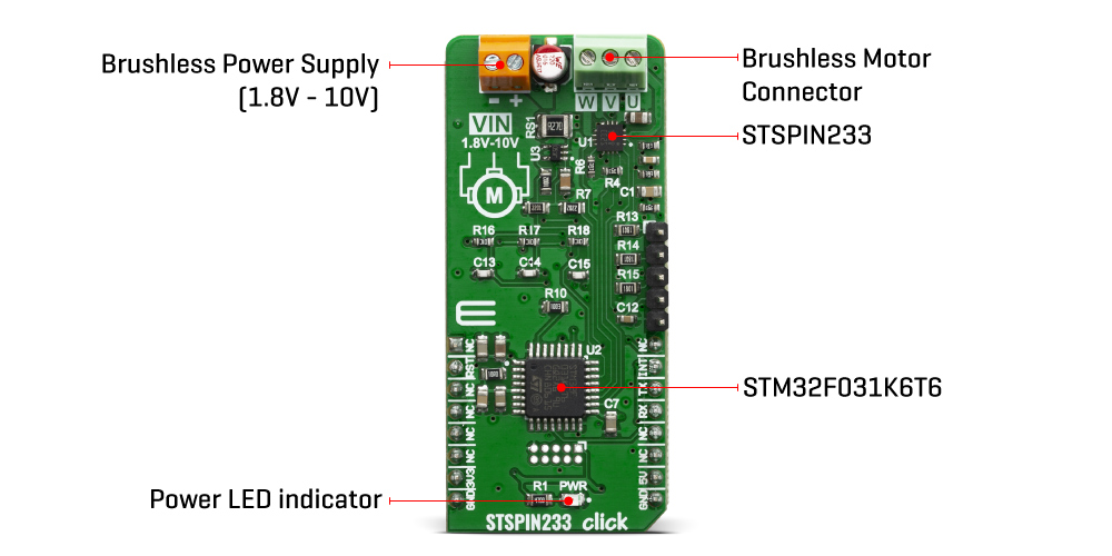
Besides the brushless driver IC, the STSPIN233 Click Board™ also has STM32F031K6T6 MCU onboard, which serves as a "brain" of the STSPIN233 Click. It comes with a preloaded firmware, which is programmed to take control of the motor driver. It reads the current motor status and signals from an optional rotary encoder, calculates values of desired and real motor status in real time and makes necessary corrections to the motor driver. The motor can be controlled by using these pins: RST, INT, and UART pins – RX and TX. That way, very reliable brushless motor driver is achieved.
The RST pin of the STSPIN233 Click is used to set both bridge outputs in HIGH-Z mod, disconnecting the power supply from the H-Bridges. This pin allows lower average power consumption as no current can flow from the power supply to the motor. This pin is routed to the RST pin of the mikroBUS™.
The INT pin has a double purpose: when set to a high logic level, it acts as a chip enable, allowing the device to operate. In the case of a fault condition on the IC, it will be asserted to a LOW logic level, acting as an interrupt pin. After a timeout period defined by the external capacitor and resistor values, a restart attempt will be made. This pin is routed to both INT pin of the mikroBUS™, allowing the host MCU to use both functions. The mentioned pin is labelled as FLT on the Click board™, respectively.
The motor power supply can be connected to the input terminal labelled as VIN and should be within the range of 1.8V to 10V. Brushless motor coils can be connected to the terminals labelled as U, V, and W. The STSPIN233 Click Board™ requires an external power supply for the motor in order to work. However, it also requires 3.3V from the mikroBUS™ rail.
| Type | Brushed |
| Applications | The STSPIN233 Click Board™ is perfectly suited for rapid development of various battery-powered stepper motor applications, including toys, printers, mechatronics, drones, robotics-related applications, etc. |
| On-board modules | STSPIN233, a low voltage DC brushed motor driver by STMicroelectronics. |
| Key Features | The main IC features a set of protection features, allowing reliable performance. It is optimized for a low-power and battery-operated applications, featuring very low ON resistance, and lowest standby current on the market. |
| Interface | GPIO,UART |
| Compatibility | mikroBUS |
| Click board size | L (57.15 x 25.4 mm) |
| Input Voltage | 3.3V,5V |
This table shows how the pinout of the STSPIN233 Click Board™ corresponds to the pinout on the mikroBUS™ socket (the latter shown in the two middle columns).
| Notes | Pin | Pin | Notes | ||||
|---|---|---|---|---|---|---|---|
| NC | 1 | AN | PWM | 16 | NC | ||
| Reset Input | RST | 2 | RST | INT | 15 | INT | Fault Interrupt Out |
| NC | 3 | CS | RX | 14 | RX | UART Receive | |
| NC | 4 | SCK | TX | 13 | TX | UART Transmit | |
| NC | 5 | MISO | SCL | 12 | NC | ||
| NC | 6 | MOSI | SDA | 11 | NC | ||
| Power Supply | 3.3V | 7 | 3.3V | 5V | 10 | 5V | Power Supply |
| Ground | GND | 8 | GND | GND | 9 | GND | Ground |
| Label | Name | Default | Description |
|---|---|---|---|
| LD1 | PWR | - | Power LED Indicator |
| Description | Min | Typ | Max | Unit |
|---|---|---|---|---|
| Input voltage | 1.8 | - | 10 | V |
| Output current | 0 | - | 1.3 | A |
We provide a library for the STSPIN233 Click Board™ on our LibStock page, as well as a demo application (example), developed using MikroElektronika compilers. The demo can run on all the main MikroElektronika development boards.
Library contains functions for the STSPIN233 Click Board™ initialization and basic control. User has at it's disposal this library, which contains functions for waking up the module and sending commands to it. Click board can also be initialized and used with UART terminal.
void stspin233_send_single_cmd ( uint8_t *tx_buf ) - Send single commandvoid stspin233_send_double_cmd ( uint8_t *cmd_buf, uint8_t *arg_buf ) - Send double commandvoid stspin233_wakeup( ) - Module wake-up (procedure)The application is composed of three sections :
void application_task ( )
{
    uint8_t console_drdy;
    char console_rx_data;

    console_drdy = UART_Rdy_Ptr( );

    if ( console_drdy != 0 )
    {
        console_rx_data = UART_Rd_Ptr( );
        app_cmd_parser( console_rx_data );
    }
}
Additional Functions :
The full application code, and ready to use projects can be found on our LibStock page.
Other mikroE Libraries used in the example:
Depending on the development board you are using, you may need USB UART click, USB UART 2 click or RS232 click to connect to your PC, for development systems with no UART to USB interface available on the board. The terminal available in all MikroElektronika compilers, or any other terminal application of your choice, can be used to read the message.
The STSPIN233 Click Board™ is supported with mikroSDK - MikroElektronika Software Development Kit. To ensure proper operation of mikroSDK compliant Click board™ demo applications, mikroSDK should be downloaded from the LibStock and installed for the compiler you are using.
- attachments: [{"download_file":[{"download_file":"STSPIN233 Click Board™ Schematic"}],"download_filetype":[{"download_filetype":"pdf"}]},{"download_file":[{"download_file":"STMicroelectronics STSPIN233 3-Phase Motor Driver Datasheet"}],"download_filetype":[{"download_filetype":"pdf"}]}] - device_vendor: STMicroelectronics - device_type: STSPIN233 - warranty: 12 months - brand: MikroE - key_feature_1: 3-Phase Motor Driver - manufacturer: Mikroelektronika d.o.o. - target_keyword: STSPIN233 Click Board - brands: gid://shopify/Metaobject/56256004319 - breadcrumbs: ["gid://shopify/Collection/447955239135","gid://shopify/Collection/241680580797","gid://shopify/Collection/241545248957","gid://shopify/Collection/279405199549"] - customhs_code: 847330 - detailed_description: {"type":"root","children":[{"type":"heading","level":3,"children":[{"type":"text","value":"How Does The STSPIN233 Click Board™ Work?"}]},{"type":"paragraph","children":[{"type":"text","value":"The "},{"type":"text","value":"STSPIN233 Click Board™","bold":true,"italic":true},{"type":"text","value":" is optimized for driving brushless motors in portable applications. Therefore, the STSPIN233 from STMicroelectronics contains three independent H-Bridges, and each of them controls one phase of the brushless motor. These integrated H-Bridges are very efficient - with ON resistance of approximately 400mΩ (HS+LS) across each bridge. These features make STSPIN233 click perfectly suited for rapid development of various battery-powered stepper motor applications, including toys, printers, mechatronics, drones, robotics-related applications, etc."}]},{"type":"paragraph","children":[{"type":"text","value":""}]},{"type":"paragraph","children":[{"type":"text","value":"Besides the brushless driver IC, the "},{"type":"text","value":"STSPIN233 Click Board™","bold":true},{"type":"text","value":" also has STM32F031K6T6 MCU onboard, which serves as a \"brain\" of the STSPIN233 Click. It comes with a preloaded firmware, which is programmed to take control of the motor driver. It reads the current motor status and signals from an optional rotary encoder, calculates values of desired and real motor status in real time and makes necessary corrections to the motor driver. The motor can be controlled by using these pins: RST, INT, and UART pins – RX and TX. That way, very reliable brushless motor driver is achieved."}]},{"type":"paragraph","children":[{"type":"text","value":"The RST pin of the STSPIN233 Click is used to set both bridge outputs in HIGH-Z mod, disconnecting the power supply from the H-Bridges. This pin allows lower average power consumption as no current can flow from the power supply to the motor. This pin is routed to the RST pin of the mikroBUS™."}]},{"type":"paragraph","children":[{"type":"text","value":"The INT pin has a double purpose: when set to a high logic level, it acts as a chip enable, allowing the device to operate. In the case of a fault condition on the IC, it will be asserted to a LOW logic level, acting as an interrupt pin. After a timeout period defined by the external capacitor and resistor values, a restart attempt will be made. This pin is routed to both INT pin of the mikroBUS™, allowing the host MCU to use both functions. The mentioned pin is labelled as FLT on the Click board™, respectively."}]},{"type":"paragraph","children":[{"type":"text","value":"The motor power supply can be connected to the input terminal labelled as VIN and should be within the range of 1.8V to 10V. Brushless motor coils can be connected to the terminals labelled as U, V, and W. The "},{"type":"text","value":"STSPIN233 Click Board™","bold":true},{"type":"text","value":" requires an external power supply for the motor in order to work. However, it also requires 3.3V from the mikroBUS™ rail."}]},{"type":"heading","level":3,"children":[{"type":"text","value":"SPECIFICATIONS"}]},{"type":"paragraph","children":[{"type":"text","value":"Type\nBrushed\nApplications\nThe STSPIN233 Click Board™ is perfectly suited for rapid development of various battery-powered stepper motor applications, including toys, printers, mechatronics, drones, robotics-related applications, etc.\nOn-board modules\nSTSPIN233, a low voltage DC brushed motor driver by STMicroelectronics.\nKey Features\nThe main IC features a set of protection features, allowing reliable performance. It is optimized for a low-power and battery-operated applications, featuring very low ON resistance, and lowest standby current on the market.\nInterface\nGPIO,UART\nCompatibility\nmikroBUS\nClick board size\nL (57.15 x 25.4 mm)\nInput Voltage\n3.3V,5V"}]},{"type":"heading","level":3,"children":[{"type":"text","value":"PINOUT DIAGRAM"}]},{"type":"paragraph","children":[{"type":"text","value":"This table shows how the pinout of the "},{"type":"text","value":"STSPIN233 Click Board™","bold":true},{"type":"text","value":" corresponds to the pinout on the mikroBUS™ socket (the latter shown in the two middle columns)."}]},{"type":"paragraph","children":[{"type":"text","value":"Notes\nPin\nPin\nNotes\nNC\n1\nAN\nPWM\n16\nNC\nReset Input\nRST\n2\nRST\nINT\n15\nINT\nFault Interrupt Out\nNC\n3\nCS\nRX\n14\nRX\nUART Receive\nNC\n4\nSCK\nTX\n13\nTX\nUART Transmit\nNC\n5\nMISO\nSCL\n12\nNC\nNC\n6\nMOSI\nSDA\n11\nNC\nPower Supply\n3.3V\n7\n3.3V\n5V\n10\n5V\nPower Supply\nGround\nGND\n8\nGND\nGND\n9\nGND\nGround"}]},{"type":"heading","level":3,"children":[{"type":"text","value":"ONBOARD SETTINGS AND INDICATORS"}]},{"type":"paragraph","children":[{"type":"text","value":"Label\nName\nDefault\nDescription\nLD1\nPWR\n-\nPower LED Indicator"}]},{"type":"heading","level":3,"children":[{"type":"text","value":"STSPIN233 CLICK ELECTRICAL SPECIFICATIONS"}]},{"type":"paragraph","children":[{"type":"text","value":"Description\nMin\nTyp\nMax\nUnit\nInput voltage\n1.8\n-\n10\nV\nOutput current\n0\n-\n1.3\nA"}]},{"type":"heading","level":3,"children":[{"type":"text","value":" "}]}]} - summary:The STSPIN233 Click Board™ is a complete solution for a 3-phase integrated motor driver, based on the STSPIN233, Low voltage 3-phase integrated motor driver. It is optimized for battery-powered, low voltage motor driving applications, featuring the lowest standby current available on the market (max 80 nA).
The STSPIN233 is a high-efficiency motor driver, featuring low ON resistance MOSFETs as the output stage, and extremely low leakage current (max 1µA). Its output stage implements the PWM current control with fixed OFF time, along with a full set of protection features. The device can be used with the step motor voltage ranging from 1.8V to 10V, and current up to 1.3A per bridge.