The STSPIN250 Click Board™ is optimized for driving brushed DC motors using batteries. Therefore, the STSPIN250 integrates very efficient H-Bridges in a parallel configuration, with a total ON resistance (HS+LS) of approximately 200mΩ. The PWM current controller allows for a programmable OFF time. Also, the motor current limit can be set by an onboard potentiometer. These features make STSPIN250 Click Board™ perfectly suited for rapid development of various battery-powered and portable brushed DC motor applications, including home appliances (such as toothbrushes and shavers), toys, portable printers, mechatronics, and robotics-related applications, etc.
The STSPIN250 Click Board™ is based on the STSPIN250, a low voltage DC brushed motor driver by STMicroelectronics. This device integrates two full-bridge MOSFET channels in a parallel configuration, which can sustain up to 2.6A. This IC is targeted towards battery-powered applications, featuring optimizations toward lowered power consumption. It has a PWM current controller that has a fixed OFF time, during which the current decay sequence is performed. This effectively limits the current through the connected load (motor). The OFF (decay) time is fixed to approximately 40 µs on this Click board™.
The PWM current controller compares the voltage across the sense resistor (VSENS) and the VREF voltage, which is adjustable on the STSPIN250 Click Board™. When VSENS becomes greater than the VREF voltage, the current limiting is triggered, and the OFF timer starts counting. The decay sequence is performed. By using a simple formula, the VREF voltage can be determined, for a specific load current:
VREF = RSENS · ILOAD
Where:
By knowing the RSENS, it can be easily calculated how much voltage should be applied to the REF pin of the STSPIN250, to limit the current according to ILOAD. For example, if there is 0.388V applied at the VREF pin, the current limit will be maxed out to 2.58A. The onboard potentiometer allows to simply adjust the VREF voltage, according to needs.
The connected motor can be controlled by using these pins: PWM, PH, RST, and EN/INT:
The PH pin determines the direction of the current. If set to a HIGH logic level, the current will flow in one direction, and vice-versa: when a LOW logic level is applied, the current will reverse its direction. This pin is routed to the AN pin of the mikroBUS™ and labelled as PH.
PWM pin can be used to regulate the speed of the rotation. When there is a LOW logic level on this pin, the current will start circulating through the low-side (LS) MOSFETs and the motor coil. When there is a HIGH logic level on this pin, the current will flow through the load, depending on the logic state of the PH pin. Higher duty cycle percentage will result in higher angular speed. While the current decay sequence is performed, the logic states on the input pins will be disregarded until the decay timer expires. The decay time is fixed to approximately 40 µs on this Click board™.
The STBY/RESET (RST) pin of the STSPIN250 is used to set both bridge outputs in HIGH-Z mode, disconnecting the power supply from the output stage. This pin allows lower average power consumption as no current can flow from the power supply to the motor. This pin is routed to the RST pin of the mikroBUS™.
The EN/FAULT (EN) pin has a double purpose: when set to a high logic level, it acts as a chip enable, allowing the device to operate. In the case of a fault condition on the IC, it will be asserted to a LOW logic level, acting as an interrupt pin. After a timeout period defined by the external capacitor and resistor values, a restart attempt will be made. This pin is routed to both CS and INT pin of the mikroBUS™, allowing the host MCU to use both functions. These pins are labelled as EN and FLT on the Click board™, respectively.
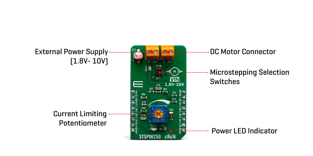
The motor power supply can be connected to the input terminal labelled as VIN and should be within the range of 1.8V to 10V. The motor can be connected at the second terminal, between two poles labelled as A+ and A-. The STSPIN250 Click Board™ requires an external power supply for the motor in order to work. However, it also requires 3.3V from the mikroBUS™ rail.
| Type | Brushed |
| Applications | The STSPIN250 Click Board™ is perfectly suited for rapid development of various battery-powered and portable brushed DC motor applications, including home appliances (such as toothbrushes and shavers), toys, portable printers, mechatronics, and robotics-related applications, etc. |
| On-board modules | STSPIN250, a low voltage DC brushed motor driver by STMicroelectronics. |
| Key Features | The main IC features a set of protection features, allowing reliable performance. The current limit can be adjusted by an onboard potentiometer. It is optimized for a low-power and battery-operated applications, featuring very low ON resistance, and lowest standby current on the market. |
| Interface | GPIO,PWM |
| Compatibility | mikroBUS |
| Click board size | M (42.9 x 25.4 mm) |
| Input Voltage | 3.3V,5V |
This table shows how the pinout of the STSPIN250 Click Board™ corresponds to the pinout on the mikroBUS™ socket (the latter shown in the two middle columns).
| Notes | Pin | Pin | Notes | ||||
|---|---|---|---|---|---|---|---|
| Direction Control | PH | 1 | AN | PWM | 16 | PWM | PWM Speed Control |
| Chip Standby/Reset | RST | 2 | RST | INT | 15 | FLT | Flaut Reporting |
| Chip Enable | EN | 3 | CS | RX | 14 | NC | |
| NC | 4 | SCK | TX | 13 | NC | ||
| NC | 5 | MISO | SCL | 12 | NC | ||
| NC | 6 | MOSI | SDA | 11 | NC | ||
| Power Supply | 3.3V | 7 | 3.3V | 5V | 10 | 5V | Power Supply |
| Ground | GND | 8 | GND | GND | 9 | GND | Ground |
| Description | Min | Typ | Max | Unit |
|---|---|---|---|---|
| Input voltage | 1.8 | 10 | V | |
| Output current | 0 | 2.6 | A |
| Label | Name | Default | Description |
|---|---|---|---|
| PWR | PWR | - | Power LED Indicator |
| VR1 | - | - | Potentiometer for current limiting |
STSPIN250 Click Board™
- amazon_main_image: https://www.thedebugstore.com/images/product/lg-stspin250-click-3543-front_1.jpg - amazon_other_image_1: https://www.thedebugstore.com/images/product/lg-stspin250-click-3543-back_1.jpg - amazon_other_image_2: https://www.thedebugstore.com/images/product/lg-stspin250-click-3543-in-use_1.jpg - amazon_other_image_3: https://www.thedebugstore.com/images/product/lg-stspin250-click-3543-in-use_1.jpg - amazon_browse_node: 428655031 - mpn: MIKROE-3543 - backorder_label: If no stock shown above, check availability - badge: - widget:We provide a library for the STSPIN250 Click Board™ on our LibStock page, as well as a demo application (example), developed using MikroElektronika compilers. The demo can run on all the main MikroElektronika development boards.
Initializes and defines gpio driver and constant values witch can be used in example code, and also performs the chip enable.
void stspin250_enable(uint8_t state) - Function for enable or disable device.void stspin250_setPH(uint8_t state) - Function for select the direction of rotation of the motor.The application is composed of the three sections :
void applicationTask()
{
// PWM DEMO EXAMPLE
    _dutyCycle += 250;
    stspin250_pwmSetDuty(_dutyCycle);
    if (_dutyCycle > 40000 )
    {
        _dutyCycle = 0;
        stspin250_pwmStop();
        Delay_ms(2000);
        stspin250_pwmStart();
    }
	stspin250_setPH(1);
    Delay_ms( 200 );
}
The full application code, and ready to use projects can be found on our LibStock page.
Other mikroE Libraries used in the example:
GPIOPWMDepending on the development board you are using, you may need USB UART click, USB UART 2 click or RS232 click to connect to your PC, for development systems with no UART to USB interface available on the board. The terminal available in all MikroElektronika compilers, or any other terminal application of your choice, can be used to read the message.
The STSPIN250 Click Board™ is supported with mikroSDK - MikroElektronika Software Development Kit. To ensure proper operation of mikroSDK compliant click board demo applications, mikroSDK should be downloaded from the LibStock and installed for the compiler you are using.
- attachments: [{"download_file":[{"download_file":"STSPIN250 Click Board™ Schematic"}],"download_filetype":[{"download_filetype":"pdf"}]},{"download_file":[{"download_file":"STMicroelectronics STSPIN250 Brushed DC Motor Driver Datasheet"}],"download_filetype":[{"download_filetype":"pdf"}]}] - device_vendor: STMicroelectronics - device_type: STSPIN250 - warranty: 12 months - brand: MikroE - manufacturer: Mikroelektronika d.o.o. - target_keyword: STSPIN250 Click Board - brands: gid://shopify/Metaobject/56256004319 - breadcrumbs: ["gid://shopify/Collection/447955239135","gid://shopify/Collection/241680580797","gid://shopify/Collection/241545248957","gid://shopify/Collection/279405232317"] - customhs_code: 847330 - detailed_description: {"type":"root","children":[{"type":"paragraph","children":[{"type":"text","value":"The "},{"type":"text","value":"STSPIN250 Click Board™","bold":true,"italic":true},{"type":"text","value":" is optimized for driving brushed DC motors using batteries. Therefore, the STSPIN250 integrates very efficient H-Bridges in a parallel configuration, with a total ON resistance (HS+LS) of approximately 200mΩ. The PWM current controller allows for a programmable OFF time. Also, the motor current limit can be set by an onboard potentiometer. These features make "},{"type":"text","value":"STSPIN250 Click Board™","bold":true},{"type":"text","value":" perfectly suited for rapid development of various battery-powered and portable brushed DC motor applications, including home appliances (such as toothbrushes and shavers), toys, portable printers, mechatronics, and robotics-related applications, etc."}]},{"type":"heading","level":3,"children":[{"type":"text","value":"How Does The STSPIN250 Click Board™ Work?"}]},{"type":"paragraph","children":[{"type":"text","value":"The"},{"type":"text","value":" STSPIN250 Click Board™","bold":true},{"type":"text","value":" is based on the STSPIN250, a low voltage DC brushed motor driver by STMicroelectronics. This device integrates two full-bridge MOSFET channels in a parallel configuration, which can sustain up to 2.6A. This IC is targeted towards battery-powered applications, featuring optimizations toward lowered power consumption. It has a PWM current controller that has a fixed OFF time, during which the current decay sequence is performed. This effectively limits the current through the connected load (motor). The OFF (decay) time is fixed to approximately 40 µs on this Click board™."}]},{"type":"paragraph","children":[{"type":"text","value":""}]},{"type":"paragraph","children":[{"type":"text","value":"The PWM current controller compares the voltage across the sense resistor (VSENS) and the VREF voltage, which is adjustable on the "},{"type":"text","value":"STSPIN250 Click Board™","bold":true},{"type":"text","value":". When VSENS becomes greater than the VREF voltage, the current limiting is triggered, and the OFF timer starts counting. The decay sequence is performed. By using a simple formula, the VREF voltage can be determined, for a specific load current:"}]},{"type":"paragraph","children":[{"type":"text","value":"VREF = RSENS · ILOAD"}]},{"type":"paragraph","children":[{"type":"text","value":"Where:"}]},{"type":"list","listType":"unordered","children":[{"type":"list-item","children":[{"type":"text","value":"VREF is the voltage on the REF pin of the STSPIN250, adjustable with the potentiometer;"}]},{"type":"list-item","children":[{"type":"text","value":"RSENS is the resistance of the current sensing resistor, which is 150 mΩ;"}]},{"type":"list-item","children":[{"type":"text","value":"ILOAD is the peak current through the motor coils;"}]}]},{"type":"paragraph","children":[{"type":"text","value":"By knowing the RSENS, it can be easily calculated how much voltage should be applied to the REF pin of the STSPIN250, to limit the current according to ILOAD. For example, if there is 0.388V applied at the VREF pin, the current limit will be maxed out to 2.58A. The onboard potentiometer allows to simply adjust the VREF voltage, according to needs."}]},{"type":"paragraph","children":[{"type":"text","value":"The connected motor can be controlled by using these pins: PWM, PH, RST, and EN/INT:"}]},{"type":"paragraph","children":[{"type":"text","value":"The PH pin determines the direction of the current. If set to a HIGH logic level, the current will flow in one direction, and vice-versa: when a LOW logic level is applied, the current will reverse its direction. This pin is routed to the AN pin of the mikroBUS™ and labelled as PH."}]},{"type":"paragraph","children":[{"type":"text","value":"PWM pin can be used to regulate the speed of the rotation. When there is a LOW logic level on this pin, the current will start circulating through the low-side (LS) MOSFETs and the motor coil. When there is a HIGH logic level on this pin, the current will flow through the load, depending on the logic state of the PH pin. Higher duty cycle percentage will result in higher angular speed. While the current decay sequence is performed, the logic states on the input pins will be disregarded until the decay timer expires. The decay time is fixed to approximately 40 µs on this Click board™."}]},{"type":"paragraph","children":[{"type":"text","value":"The STBY/RESET (RST) pin of the STSPIN250 is used to set both bridge outputs in HIGH-Z mode, disconnecting the power supply from the output stage. This pin allows lower average power consumption as no current can flow from the power supply to the motor. This pin is routed to the RST pin of the mikroBUS™."}]},{"type":"paragraph","children":[{"type":"text","value":"The EN/FAULT (EN) pin has a double purpose: when set to a high logic level, it acts as a chip enable, allowing the device to operate. In the case of a fault condition on the IC, it will be asserted to a LOW logic level, acting as an interrupt pin. After a timeout period defined by the external capacitor and resistor values, a restart attempt will be made. This pin is routed to both CS and INT pin of the mikroBUS™, allowing the host MCU to use both functions. These pins are labelled as EN and FLT on the Click board™, respectively."}]},{"type":"paragraph","children":[{"type":"text","value":"The motor power supply can be connected to the input terminal labelled as VIN and should be within the range of 1.8V to 10V. The motor can be connected at the second terminal, between two poles labelled as A+ and A-. The "},{"type":"text","value":"STSPIN250 Click Board™","bold":true},{"type":"text","value":" requires an external power supply for the motor in order to work. However, it also requires 3.3V from the mikroBUS™ rail."}]},{"type":"heading","level":3,"children":[{"type":"text","value":"SPECIFICATIONS"}]},{"type":"paragraph","children":[{"type":"text","value":"Type\nBrushed\nApplications\nThe STSPIN250 Click Board™ is perfectly suited for rapid development of various battery-powered and portable brushed DC motor applications, including home appliances (such as toothbrushes and shavers), toys, portable printers, mechatronics, and robotics-related applications, etc.\nOn-board modules\nSTSPIN250, a low voltage DC brushed motor driver by STMicroelectronics.\nKey Features\nThe main IC features a set of protection features, allowing reliable performance. The current limit can be adjusted by an onboard potentiometer. It is optimized for a low-power and battery-operated applications, featuring very low ON resistance, and lowest standby current on the market.\nInterface\nGPIO,PWM\nCompatibility\nmikroBUS\nClick board size\nM (42.9 x 25.4 mm)\nInput Voltage\n3.3V,5V"}]},{"type":"heading","level":3,"children":[{"type":"text","value":"PINOUT DIAGRAM"}]},{"type":"paragraph","children":[{"type":"text","value":"This table shows how the pinout of the "},{"type":"text","value":"STSPIN250 Click Board™","bold":true},{"type":"text","value":" corresponds to the pinout on the mikroBUS™ socket (the latter shown in the two middle columns)."}]},{"type":"paragraph","children":[{"type":"text","value":"Notes\nPin\nPin\nNotes\nDirection Control\nPH\n1\nAN\nPWM\n16\nPWM\nPWM Speed Control\nChip Standby/Reset\nRST\n2\nRST\nINT\n15\nFLT\nFlaut Reporting\nChip Enable\nEN\n3\nCS\nRX\n14\nNC\nNC\n4\nSCK\nTX\n13\nNC\nNC\n5\nMISO\nSCL\n12\nNC\nNC\n6\nMOSI\nSDA\n11\nNC\nPower Supply\n3.3V\n7\n3.3V\n5V\n10\n5V\nPower Supply\nGround\nGND\n8\nGND\nGND\n9\nGND\nGround"}]},{"type":"heading","level":3,"children":[{"type":"text","value":"STSPIN250 CLICK ELECTRICAL SPECIFICATIONS"}]},{"type":"paragraph","children":[{"type":"text","value":"Description\nMin\nTyp\nMax\nUnit\nInput voltage\n1.8\n10\nV\nOutput current\n0\n2.6\nA"}]},{"type":"heading","level":3,"children":[{"type":"text","value":"ONBOARD SETTINGS AND INDICATORS"}]},{"type":"paragraph","children":[{"type":"text","value":"Label\nName\nDefault\nDescription\nPWR\nPWR\n-\nPower LED Indicator\nVR1\n-\n-\nPotentiometer for current limiting"}]},{"type":"heading","level":3,"children":[{"type":"text","value":" "}]}]} - summary:The STSPIN250 Click Board™ is a brushed DC motor driver with the current limiting and current sensing. It is based on the STSPIN250, a low voltage DC brushed motor driver. It is optimized for portable and low voltage applications, featuring the lowest standby current available on the market (max 80nA).
Thanks to the low ON resistance of the MOSFETs used for its output stage, the STSPIN250 represents a highly efficient DC motor driver, with a very small (3x3mm QFN) form factor. The device implements a PWM current control with the fixed OFF time, along with a full set of protection features. The STSPIN250 Click Board™ can be used with the step motor voltage ranging from 1.8V to 10V, and current up to 2.6A.