The MC3216 is a low-noise, integrated digital output 3-axis accelerometer with a feature set optimized for cell phones and consumer product motion sensing. This allows very high integration and very small dimensions, at an affordable cost. Besides the size, features such as low power consumption, high precision of motion detection, high shock tolerance, and programming capabilities, make it a device which can be used for development of different types of motion detection based applications, including user interface control, gesture command, augmented reality, vehicle navigation, image stabilization in photography, electrical compass tilt compensation for cell phones and many other similar applications.
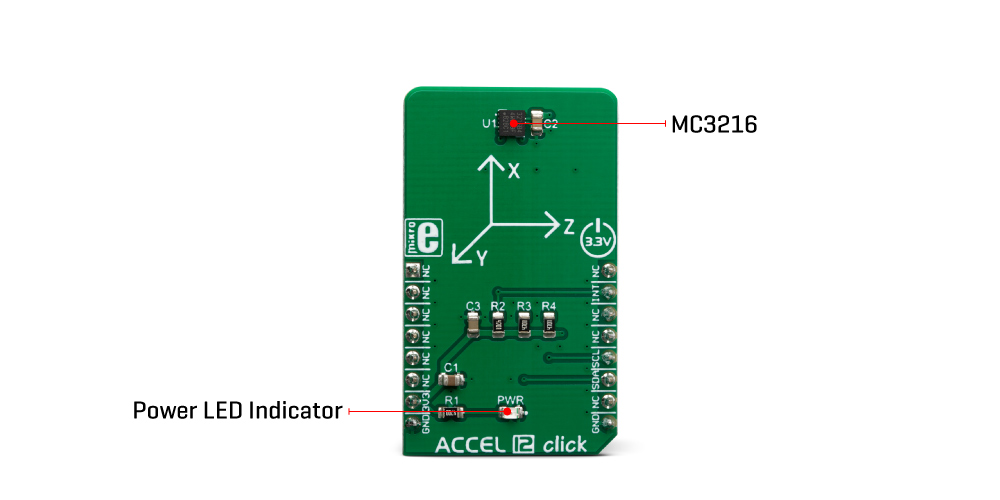
The Accel 12 Click Board™ is based around the MC3216, a low-noise and low power 3-axis accelerometer, from mCube. It is an advanced, Single-chip, 3D silicon, microelectromechanical accelerometer sensor (MEMS), combined with the powerful data processing engine. There is a respective accelerometer MEMS on each axis. The output of each MEMS is processed and digitized by a sigma-delta 14-bit A/D converter (ADC), whose resolution can be chosen between 8-bit, 10-bit or 14-bit. The outputs can be processed by a low-pass filter, while their sample rate can be selected by the user from 0.25 to 256 samples/second. Three-axis accelerometer MEMS can be programmed to measure the acceleration along each axis, in four different acceleration ranges: ±2g, ±4g, ±8g, ±12g, and ±16g. The user can select an optimal range for both properties, depending on the application requirements.
The MC3216 incorporates a directional tap detection in ±X, ±Y or ±Z. Each axis is independent, although only one direction per axis is supported simultaneously. The threshold, duration, and dead-time of tap detection can be set for each axis, and six flag/status bits are maintained in a status register. The tap hardware uses a second-order high-pass filter to detect fast impulse/transition acceleration events. The interrupt pin (INT), which is routed to the INT pin on the mikroBUS™ socket can be used to indicate that a tap event has been detected.
The device has two states of operation: standby (the default state after power-up), and wake. The standby state offers the lowest power consumption. In this state, the I2C interface is active and all register reads and writes are allowed. There is no event detection, sampling, or acceleration measurement, and internal clocking is halted. Complete access to the register set is allowed in this state, but interrupts cannot be serviced. The device defaults to the standby state following power-up. The time to change states from standby to wake is less than 10uSec. In wake state, Continuous sampling and reading of sense data are available, and all registers except the Mode Control Register are read-only.
It is worth to mention that the current consumption varies depending on the state of operation and parameters set. In the standby state, it is typically 4μA, while in wake state it varies between 50μA up to 130μA, mostly depending on the sampling rate and converter resolution.
The Accel 12 Click Board™ uses the I2C communication interface. It has pull-up resistors connected to the mikroBUS™ 3.3V rail. Proper conversion of logic voltage levels should be applied before the Click board™ is used with MCUs operated with 5V.
| Type | Acceleration,Motion |
| Applications | It is a perfect solution for user interface control, gesture command, augmented reality, vehicle navigation, image stabilization in photography, electrical compass tilt compensation for cell phones and many other similar applications. |
| On-board modules | MC3216, a low-noise, and low power 3-axis accelerometer. |
| Key Features | The output of each axis is digitized by 14-bit ADC, Event Detection feature low power consumption, high precision of motion detection, high shock tolerance, and programming capabilities |
| Interface | I2C |
| Compatibility | mikroBUS |
| Click board size | M (42.9 x 25.4 mm) |
| Input Voltage | 3.3V |
This table shows how the pinout on the Accel 12 Click Board™ corresponds to the pinout on the mikroBUS™ socket (the latter shown in the two middle columns).
| Notes | Pin | Pin | Notes | ||||
|---|---|---|---|---|---|---|---|
| NC | 1 | AN | PWM | 16 | NC | ||
| NC | 2 | RST | INT | 15 | INT | Interrupt | |
| NC | 3 | CS | RX | 14 | NC | ||
| NC | 4 | SCK | TX | 13 | NC | ||
| NC | 5 | MISO | SCL | 12 | SCL | I2C Clock | |
| NC | 6 | MOSI | SDA | 11 | SDA | I2C Data | |
| Power Supply | 3.3V | 7 | 3.3V | 5V | 10 | NC | |
| Ground | GND | 8 | GND | GND | 9 | GND | Ground |
| Label | Name | Default | Description |
|---|---|---|---|
| LD1 | PWR | - | Power LED Indicator |
The MC3216 is a low-noise, integrated digital output 3-axis accelerometer with a feature set optimized for cell phones and consumer product motion sensing. This allows very high integration and very small dimensions, at an affordable cost. Besides the size, features such as low power consumption, high precision of motion detection, high shock tolerance, and programming capabilities, make it a device which can be used for development of different types of motion detection based applications, including user interface control, gesture command, augmented reality, vehicle navigation, image stabilization in photography, electrical compass tilt compensation for cell phones and many other similar applications.
The Accel 12 Click Board is based around the MC3216, a low-noise and low power 3-axis accelerometer, from mCube. It is an advanced, Single-chip, 3D silicon, microelectromechanical accelerometer sensor (MEMS), combined with the powerful data processing engine. There is a respective accelerometer MEMS on each axis. The output of each MEMS is processed and digitized by a sigma-delta 14-bit A/D converter (ADC), whose resolution can be chosen between 8-bit, 10-bit or 14-bit. The outputs can be processed by a low-pass filter, while their sample rate can be selected by the user from 0.25 to 256 samples/second. Three-axis accelerometer MEMS can be programmed to measure the acceleration along each axis, in four different acceleration ranges: ±2g, ±4g, ±8g, ±12g, and ±16g. The user can select an optimal range for both properties, depending on the application requirements.

The MC3216 incorporates a directional tap detection in ±X, ±Y or ±Z. Each axis is independent, although only one direction per axis is supported simultaneously. The threshold, duration, and dead-time of tap detection can be set for each axis, and six flag/status bits are maintained in a status register. The tap hardware uses a second-order high-pass filter to detect fast impulse/transition acceleration events. The interrupt pin (INT), which is routed to the INT pin on the mikroBUS™ socket can be used to indicate that a tap event has been detected.
The device has two states of operation: standby (the default state after power-up), and wake. The standby state offers the lowest power consumption. In this state, the I2C interface is active and all register reads and writes are allowed. There is no event detection, sampling, or acceleration measurement, and internal clocking is halted. Complete access to the register set is allowed in this state, but interrupts cannot be serviced. The device defaults to the standby state following power-up. The time to change states from standby to wake is less than 10μSec. In wake state, Continuous sampling and reading of sense data are available, and all registers except the Mode Control Register are read-only.
It is worth to mention that the current consumption varies depending on the state of operation and parameters set. In the standby state, it is typically 4μA, while in wake state it varies between 50μA up to 130μA, mostly depending on the sampling rate and converter resolution.
The Accel 12 Click Board uses the I2C communication interface. It has pull-up resistors connected to the mikroBUS™ 3.3V rail. Proper conversion of logic voltage levels should be applied before the Click board™ is used with MCUs operated with 5V.
- amazon_main_image: https://www.thedebugstore.com/images/product/lg-accel-12-click-3464-front_1.jpg - amazon_other_image_1: https://www.thedebugstore.com/images/product/lg-accel-12-click-3464-back_1.jpg - amazon_other_image_2: https://www.thedebugstore.com/images/product/lg-accel-12-click-3464-in-use_1.jpg - amazon_other_image_3: https://www.thedebugstore.com/images/product/lg-accel-12-click-3464-in-use_1.jpg - amazon_browse_node: 428655031 - mpn: MIKROE-3464 - backorder_label: If no stock shown above, check availability - badge: - widget:We provide a library for the Accel 12 Click Board™ on our LibStock page, as well as a demo application (example), developed using MikroElektronika compilers. The demo can run on all the main MikroElektronika development boards.
The library initializes and defines the I2C bus driver and drivers that offer a choice for writing data in register. The library includes function for read X/Y/Z axis data and function for Tap detection interrupt. The user also has the function for configuration register and function for read interrupt state.
void accel12_getAxisData(int16_t *x_axis, int16_t *y_axis, int16_t *z_axis) - Accel axis data.uint8_t accel12_getTapDetection() - Tap detection.void accel12_configuration(uint8_t reg, uint8_t dataIn) - Functions for configuration register.The application is composed of three sections :
void applicationTask()
{
    /* Accelerometer measurement */
    accel12_getAxisData(&X_Axis, &Y_Axis, &Z_Axis);

    IntToStr(X_axis, demoText);
    mikrobus_logWrite(" X axis : ", _LOG_TEXT);
    mikrobus_logWrite(demoText, _LOG_LINE);

    IntToStr(Y_axis, demoText);
    mikrobus_logWrite(" Y axis : ", _LOG_TEXT);
    mikrobus_logWrite(demoText, _LOG_LINE);

    IntToStr(Z_axis, demoText);
    mikrobus_logWrite(" Z axis : ", _LOG_TEXT);
    mikrobus_logWrite(demoText, _LOG_LINE);

    /* TAP interrupt */
    tap = accel12_getTapDetection();
    switch(tap)
    {
        case 1:
        {
            mikrobus_logWrite(" X Positive ", _LOG_LINE);
            break;
        }
        case 2:
        {
            mikrobus_logWrite(" Y Positive ", _LOG_LINE);
            break;
        }
        case 3:
        {
            mikrobus_logWrite(" Z Positive ", _LOG_LINE);
            break;
        }
        case 4:
        {
            mikrobus_logWrite(" X Negative ", _LOG_LINE);
            break;
        }
        case 5:
        {
            mikrobus_logWrite(" Y Negative ", _LOG_LINE);
            break;
        }
        case 6:
        {
            mikrobus_logWrite(" Z Negative ", _LOG_LINE);
            break;
        }
    }
    mikrobus_logWrite("---------------------", _LOG_LINE);
    Delay_ms( 1500 );
}
The full application code, and ready to use projects can be found on our LibStock page.
Other mikroE Libraries used in the example:
Additional notes and informations
Depending on the development board you are using, you may need a USB UART click, USB UART 2 click or RS232 click to connect to your PC, for development systems with no UART to USB interface available on the board. The terminal available in all MikroElektronika compilers, or any other terminal application of your choice, can be used to read the message.
The Accel 12 Click Board™ is supported with mikroSDK - MikroElektronika Software Development Kit. To ensure proper operation of mikroSDK compliant Click board demo applications, mikroSDK should be downloaded from the LibStock and installed for the compiler you are using.
- attachments: [{"download_file":[{"download_file":"Accel 12 Click Board™ Schematic"}],"download_filetype":[{"download_filetype":"pdf"}]},{"download_file":[{"download_file":"mCube MC3216 3-Axis Accelerometer Datasheet"}],"download_filetype":[{"download_filetype":"pdf"}]}] - condition: new - custom_product: false - mpn: MIKROE-3464 - google_product_category: Electronics - custom_label_0: Click Board - device_vendor: mCube - device_type: MC3216 - warranty: 12 months - brand: MikroE - key_feature_1: Three-axis Motion Tracker - manufacturer: Mikroelektronika d.o.o. - target_keyword: Accel 12 Click Board - brands: gid://shopify/Metaobject/56256004319 - breadcrumbs: ["gid://shopify/Collection/447955239135","gid://shopify/Collection/241680580797","gid://shopify/Collection/241545969853"] - customhs_code: 847330 - detailed_description: {"type":"root","children":[{"type":"paragraph","children":[{"type":"text","value":"The MC3216 is a low-noise, integrated digital output 3-axis accelerometer with a feature set optimized for cell phones and consumer product motion sensing. This allows very high integration and very small dimensions, at an affordable cost. Besides the size, features such as low power consumption, high precision of motion detection, high shock tolerance, and programming capabilities, make it a device which can be used for development of different types of motion detection based applications, including user interface control, gesture command, augmented reality, vehicle navigation, image stabilization in photography, electrical compass tilt compensation for cell phones and many other similar applications."}]},{"type":"heading","level":3,"children":[{"type":"text","value":"How Does The Accel 12 Click Board™ Work?"}]},{"type":"paragraph","children":[{"type":"text","value":"The "},{"type":"text","value":"Accel 12 Click Board™","bold":true},{"type":"text","value":" is based around the MC3216, a low-noise and low power 3-axis accelerometer, from mCube. It is an advanced, Single-chip, 3D silicon, microelectromechanical accelerometer sensor (MEMS), combined with the powerful data processing engine. There is a respective accelerometer MEMS on each axis. The output of each MEMS is processed and digitized by a sigma-delta 14-bit A/D converter (ADC), whose resolution can be chosen between 8-bit, 10-bit or 14-bit. The outputs can be processed by a low-pass filter, while their sample rate can be selected by the user from 0.25 to 256 samples/second. Three-axis accelerometer MEMS can be programmed to measure the acceleration along each axis, in four different acceleration ranges: ±2g, ±4g, ±8g, ±12g, and ±16g. The user can select an optimal range for both properties, depending on the application requirements."}]},{"type":"paragraph","children":[{"type":"text","value":""}]},{"type":"paragraph","children":[{"type":"text","value":"The MC3216 incorporates a directional tap detection in ±X, ±Y or ±Z. Each axis is independent, although only one direction per axis is supported simultaneously. The threshold, duration, and dead-time of tap detection can be set for each axis, and six flag/status bits are maintained in a status register. The tap hardware uses a second-order high-pass filter to detect fast impulse/transition acceleration events. The interrupt pin (INT), which is routed to the INT pin on the mikroBUS™ socket can be used to indicate that a tap event has been detected."}]},{"type":"paragraph","children":[{"type":"text","value":"The device has two states of operation: standby (the default state after power-up), and wake. The standby state offers the lowest power consumption. In this state, the I2C interface is active and all register reads and writes are allowed. There is no event detection, sampling, or acceleration measurement, and internal clocking is halted. Complete access to the register set is allowed in this state, but interrupts cannot be serviced. The device defaults to the standby state following power-up. The time to change states from standby to wake is less than 10uSec. In wake state, Continuous sampling and reading of sense data are available, and all registers except the Mode Control Register are read-only."}]},{"type":"paragraph","children":[{"type":"text","value":"It is worth to mention that the current consumption varies depending on the state of operation and parameters set. In the standby state, it is typically 4μA, while in wake state it varies between 50μA up to 130μA, mostly depending on the sampling rate and converter resolution."}]},{"type":"paragraph","children":[{"type":"text","value":"The "},{"type":"text","value":"Accel 12 Click Board™","bold":true},{"type":"text","value":" uses the I2C communication interface. It has pull-up resistors connected to the mikroBUS™ 3.3V rail. Proper conversion of logic voltage levels should be applied before the Click board™ is used with MCUs operated with 5V."}]},{"type":"heading","level":3,"children":[{"type":"text","value":"SPECIFICATIONS"}]},{"type":"paragraph","children":[{"type":"text","value":"Type\nAcceleration,Motion\nApplications\nIt is a perfect solution for user interface control, gesture command, augmented reality, vehicle navigation, image stabilization in photography, electrical compass tilt compensation for cell phones and many other similar applications.\nOn-board modules\nMC3216, a low-noise, and low power 3-axis accelerometer.\nKey Features\nThe output of each axis is digitized by 14-bit ADC, Event Detection feature low power consumption, high precision of motion detection, high shock tolerance, and programming capabilities\nInterface\nI2C\nCompatibility\nmikroBUS\nClick board size\nM (42.9 x 25.4 mm)\nInput Voltage\n3.3V"}]},{"type":"heading","level":3,"children":[{"type":"text","value":"PINOUT DIAGRAM"}]},{"type":"paragraph","children":[{"type":"text","value":"This table shows how the pinout on the "},{"type":"text","value":"Accel 12 Click Board™","bold":true},{"type":"text","value":" corresponds to the pinout on the mikroBUS™ socket (the latter shown in the two middle columns)."}]},{"type":"paragraph","children":[{"type":"text","value":"Notes\nPin\nPin\nNotes\nNC\n1\nAN\nPWM\n16\nNC\nNC\n2\nRST\nINT\n15\nINT\nInterrupt\nNC\n3\nCS\nRX\n14\nNC\nNC\n4\nSCK\nTX\n13\nNC\nNC\n5\nMISO\nSCL\n12\nSCL\nI2C Clock\nNC\n6\nMOSI\nSDA\n11\nSDA\nI2C Data\nPower Supply\n3.3V\n7\n3.3V\n5V\n10\nNC\nGround\nGND\n8\nGND\nGND\n9\nGND\nGround"}]},{"type":"heading","level":3,"children":[{"type":"text","value":"ONBOARD SETTINGS AND INDICATORS"}]},{"type":"paragraph","children":[{"type":"text","value":"Label\nName\nDefault\n Description\nLD1\nPWR\n-\nPower LED Indicator"}]},{"type":"heading","level":3,"children":[{"type":"text","value":" "}]}]} - summary:The Accel 12 Click Board™ is an advanced 3-axis motion tracking Click Board™, which utilises the MC3216, a low-noise, and low power 3-axis accelerometer. This Click Board™ allows linear motion and gravitational force measurements in ranges of ±2 g, ±4 g, ±8, and ±16 g in three perpendicular axes and support directional tap detection in ±X, ±Y or ±Z. The output of each axis is digitised by 14-bit ADC and offered directly, over the standard I2C Interface. The built-in Event Detection feature allows the user to set an interrupt when a specific event is detected.