The MUX 2 Click Board™ is equipped with the MUX508, a precise analog multiplexing IC, produced by Texas Instruments. The MUX508 can be used with a wide range of power supplies. It can handle both dual and single power supplies, as well as the symmetrical and non-symmetrical ones. This allows it to be used in a very wide range of different applications. Four control pins are used to switch one of eight inputs to a single output. Control pins labeled as A0, A1, and A2 are routed to the mikroBUS™ and can be operated by both 3.3V and 5V MCUs. The fourth control pin is labeled as EN pin, and it is used to enable the internal multiplexing switches of the IC, when is set to a HIGH logic level (it is active HIGH). A0, A1, and A2 pins are routed to RST, PWM, and INT pins of the mikroBUS™ respectively, while the EN pin is routed to the CS pin on the mikroBUS™.
The MUX508 IC is targeted towards working with both bipolar and unipolar single-ended inputs. Each input is labeled as S1 to S8. When a specific channel is selected by using the A0 to A2 pins, it will be switched to the output pin, labeled as D. For the improved stability, each pin is equipped with the 100nF parallel capacitor and 100Ω series resistance. The input and the output signal pins are routed to the standard 2.54mm pitch 2x5 pins header on the Click board™.
The ultra-low leakage current ensures that there is no signal interference from the inputs that are not selected by the A0, A1, and A2 pins. A low crosstalk also ensures that the signal on one channel remains clean of interferences caused by other channels. To prevent any two inputs to be switched at the output at the same time, a break-before-make switching action is utilized. This ensures a reliable operation of the IC and the Click board™ itself.
The MUX 2 Click Board™ does not use the power from the mikroBUS™ power rails, except for the LED indicator. Instead, a three-pole screw terminal is used to connect an external power supply. Having in mind the minimum input voltage of 10V or ±5V, a power supply should be connected to this terminal before operating the MUX 2 Click Board™. The input and output signals can be connected via the 2x5 pins header. As mentioned before, the MUX508 IC supports rail-to-rail operation. Independent power supply input allows the user to work with a wide range of signal amplitudes, depending on the application requirements, as long as the power supply stays within the limits.
More information about the MUX508 can be found in the attached datasheet. However, the MUX 2 Click Board™ comes equipped with a library that contains easy to use functions and a usage example that may be used as a reference for the development.
| Type | DAC |
| Applications | Automatization and process control, programmable logic controllers, digital multimeters, battery monitoring, and other applications that require differential signal switching. |
| On-board modules | MUX508, a precise analog multiplexing IC, produced by Texas Instruments |
| Key Features | Features such as the break-before-make switching action, electrostatic discharge protection up to 2kV, low on-resistance and low input current leakage, make this circuit a perfect solution for various switching applications, especially those that utilize differential signals |
| Interface | GPIO |
| Compatibility | mikroBUS |
| Click board size | M (42.9 x 25.4 mm) |
| Input Voltage | 5V |
This table shows how the pinout on the MUX 2 Click Board™ corresponds to the pinout on the mikroBUS™ socket (the latter shown in the two middle columns).
| Notes | Pin | Pin | Notes | ||||
|---|---|---|---|---|---|---|---|
| NC | 1 | AN | PWM | 16 | A1 | Control pin 1 | |
| Control pin 0 | A0 | 2 | RST | INT | 15 | A2 | Control pin 2 |
| Chip Enable | EN | 3 | CS | RX | 14 | NC | |
| NC | 4 | SCK | TX | 13 | NC | ||
| NC | 5 | MISO | SCL | 12 | NC | ||
| NC | 6 | MOSI | SDA | 11 | NC | ||
| NC | 7 | 3.3V | 5V | 10 | 5V | Power Supply | |
| Ground | GND | 8 | GND | GND | 9 | GND | Ground |
| Label | Name | Default | Description |
|---|---|---|---|
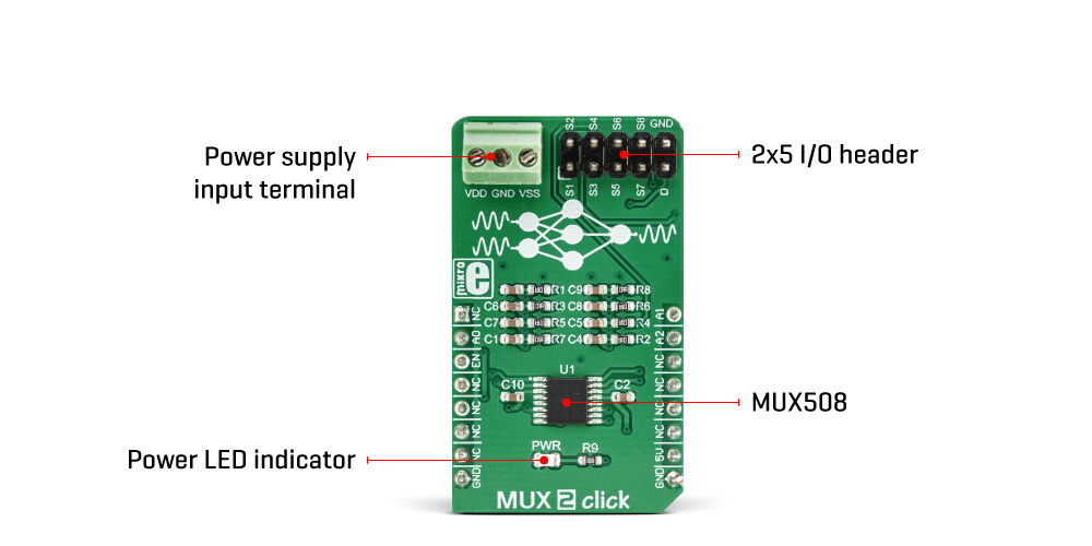
| LD1 | PWR | - | Power LED indicator |
| J1 | - | - | 2x5 pins I/O header |
| CN1 | - | - | Power supply input terminal |
| Description | Min | Typ | Max | Unit |
|---|---|---|---|---|
| VIN (voltage at the power supply input terminal, single supply) | 10 | - | 36 | V |
| VIN (voltage at the power supply input terminal, symmetrical supply) | ±5 | - | ±18 | V |
MUX 2 Click Board™ is a Click Board™ that switches one of the eight inputs to one output. It employs the MUX508, a modern CMOS analog multiplexing integrated circuit, produced by Texas Instruments. This IC can be powered with both dual power supplies, ranging from ±5V to ±18V, and single power supplies, ranging from 10V to 36V. It offers rail-to-rail operation, allowing the input signal to swing up (and down) to the voltage of the power supply, with no distortion. Features such as the break-before-make switching action, electrostatic discharge protection up to 2kV, low on-resistance and low input current leakage, make this circuit a perfect solution for various switching applications, operating with both unipolar and bipolar signals.
It comes in the package which also includes the mikroSDK software and a library with all the functions. The Click Board™ comes as a fully tested and approved prototype, making it a reliable device ready to use on the development board.
- amazon_main_image: https://www.thedebugstore.com/images/product/lg-mux-2-front_1.jpg - amazon_other_image_1: https://www.thedebugstore.com/images/product/lg-mux-2-back_1.jpg - amazon_other_image_2: https://www.thedebugstore.com/images/product/lg-mux-2-click-in-use_1.jpg - amazon_browse_node: 428655031 - mpn: MIKROE-3245 - backorder_label: If no stock shown above, check availability - badge: - widget:We provide a library for the MUX 2 Click Board™ on our LibStock page, as well as a demo application (example), developed using MikroElektronika compilers. The demo can run on all the main MikroElektronika development boards.
The library includes function for set current active mux channel and function for enable or disble mux device.
void mux2_activeMuxChannel(uint8_t ch) - Functions for set active MUX channelvoid mux2_deviceEnable() - Functions for enable MUX deviceThe application is composed of the three sections :
void applicationTask()
{
     mux2_activeMuxChannel(_MUX2_CHANNEL_S1);
     Delay_ms( 5000 );
     mux2_activeMuxChannel(_MUX2_CHANNEL_S2);
     Delay_ms( 5000 );
     mux2_activeMuxChannel(_MUX2_CHANNEL_S3);
     Delay_ms( 5000 );
     mux2_activeMuxChannel(_MUX2_CHANNEL_S4);
     Delay_ms( 5000 );
     mux2_activeMuxChannel(_MUX2_CHANNEL_S5);
     Delay_ms( 5000 );
     mux2_activeMuxChannel(_MUX2_CHANNEL_S6);
     Delay_ms( 5000 );
     mux2_activeMuxChannel(_MUX2_CHANNEL_S7);
     Delay_ms( 5000 );
     mux2_activeMuxChannel(_MUX2_CHANNEL_S8);
     Delay_ms( 5000 );

}
The full application code, and ready to use projects can be found on our LibStock page.
Other mikroE Libraries used in the example:
GPIODepending on the development board you are using, you may need a USB UART click, USB UART 2 click or RS232 click to connect to your PC, for development systems with no UART to USB interface available on the board. The terminal available in all MikroElektronika compilers, or any other terminal application of your choice, can be used to read the message.
The MUX 2 Click Board™ is supported with mikroSDK - MikroElektronika Software Development Kit. To ensure proper operation of mikroSDK compliant click board demo applications, mikroSDK should be downloaded from the LibStock and installed for the compiler you are using.
- attachments: [{"download_file":[{"download_file":"MUX 2 Click Board™ Schematic"}],"download_filetype":[{"download_filetype":"pdf"}]},{"download_file":[{"download_file":"Texas Instruments Analog Multiplexer Datasheet"}],"download_filetype":[{"download_filetype":"pdf"}]}] - condition: new - custom_product: false - mpn: MIKROE-3245 - google_product_category: Electronics - custom_label_0: Click Board - device_vendor: Texas Instruments - device_type: MUX508IPWR - warranty: 12 months - brand: MikroE - key_feature_1: Eight-Channel Analog Multiplexer - manufacturer: Mikroelektronika d.o.o. - brands: gid://shopify/Metaobject/56256004319 - breadcrumbs: ["gid://shopify/Collection/447955239135","gid://shopify/Collection/241680580797","gid://shopify/Collection/241545314493"] - customhs_code: 847330 - detailed_description: {"type":"root","children":[{"type":"heading","level":3,"children":[{"type":"text","value":"How Does The MUX 2 Click Board™ Work?"}]},{"type":"paragraph","children":[{"type":"text","value":"The "},{"type":"text","value":"MUX 2 Click Board™","bold":true},{"type":"text","value":" is equipped with the MUX508, a precise analog multiplexing IC, produced by Texas Instruments. The MUX508 can be used with a wide range of power supplies. It can handle both dual and single power supplies, as well as the symmetrical and non-symmetrical ones. This allows it to be used in a very wide range of different applications. Four control pins are used to switch one of eight inputs to a single output. Control pins labeled as A0, A1, and A2 are routed to the mikroBUS™ and can be operated by both 3.3V and 5V MCUs. The fourth control pin is labeled as EN pin, and it is used to enable the internal multiplexing switches of the IC, when is set to a HIGH logic level (it is active HIGH). A0, A1, and A2 pins are routed to RST, PWM, and INT pins of the mikroBUS™ respectively, while the EN pin is routed to the CS pin on the mikroBUS™."}]},{"type":"paragraph","children":[{"type":"text","value":""}]},{"type":"paragraph","children":[{"type":"text","value":"The MUX508 IC is targeted towards working with both bipolar and unipolar single-ended inputs. Each input is labeled as S1 to S8. When a specific channel is selected by using the A0 to A2 pins, it will be switched to the output pin, labeled as D. For the improved stability, each pin is equipped with the 100nF parallel capacitor and 100Ω series resistance. The input and the output signal pins are routed to the standard 2.54mm pitch 2x5 pins header on the Click board™."}]},{"type":"paragraph","children":[{"type":"text","value":"The ultra-low leakage current ensures that there is no signal interference from the inputs that are not selected by the A0, A1, and A2 pins. A low crosstalk also ensures that the signal on one channel remains clean of interferences caused by other channels. To prevent any two inputs to be switched at the output at the same time, a break-before-make switching action is utilized. This ensures a reliable operation of the IC and the Click board™ itself."}]},{"type":"paragraph","children":[{"type":"text","value":"The "},{"type":"text","value":"MUX 2 Click Board™","bold":true},{"type":"text","value":" does not use the power from the mikroBUS™ power rails, except for the LED indicator. Instead, a three-pole screw terminal is used to connect an external power supply. Having in mind the minimum input voltage of 10V or ±5V, a power supply should be connected to this terminal before operating the "},{"type":"text","value":"MUX 2 Click Board™","bold":true},{"type":"text","value":". The input and output signals can be connected via the 2x5 pins header. As mentioned before, the MUX508 IC supports rail-to-rail operation. Independent power supply input allows the user to work with a wide range of signal amplitudes, depending on the application requirements, as long as the power supply stays within the limits."}]},{"type":"paragraph","children":[{"type":"text","value":"More information about the MUX508 can be found in the attached datasheet. However, the "},{"type":"text","value":"MUX 2 Click Board™","bold":true},{"type":"text","value":" comes equipped with a library that contains easy to use functions and a usage example that may be used as a reference for the development."}]},{"type":"heading","level":3,"children":[{"type":"text","value":"SPECIFICATIONS"}]},{"type":"paragraph","children":[{"type":"text","value":"Type\nDAC\nApplications\nAutomatization and process control, programmable logic controllers, digital multimeters, battery monitoring, and other applications that require differential signal switching.\nOn-board modules\nMUX508, a precise analog multiplexing IC, produced by Texas Instruments\nKey Features\nFeatures such as the break-before-make switching action, electrostatic discharge protection up to 2kV, low on-resistance and low input current leakage, make this circuit a perfect solution for various switching applications, especially those that utilize differential signals\nInterface\nGPIO\nCompatibility\nmikroBUS\nClick board size\nM (42.9 x 25.4 mm)\nInput Voltage\n5V"}]},{"type":"heading","level":3,"children":[{"type":"text","value":"PINOUT DIAGRAM"}]},{"type":"paragraph","children":[{"type":"text","value":"This table shows how the pinout on the "},{"type":"text","value":"MUX 2 Click Board™","bold":true},{"type":"text","value":" corresponds to the pinout on the mikroBUS™ socket (the latter shown in the two middle columns)."}]},{"type":"paragraph","children":[{"type":"text","value":"Notes\nPin\nPin\nNotes\nNC\n1\nAN\nPWM\n16\nA1\nControl pin 1\nControl pin 0\nA0\n2\nRST\nINT\n15\nA2\nControl pin 2\nChip Enable\nEN\n3\nCS\nRX\n14\nNC\nNC\n4\nSCK\nTX\n13\nNC\nNC\n5\nMISO\nSCL\n12\nNC\nNC\n6\nMOSI\nSDA\n11\nNC\nNC\n7\n3.3V\n5V\n10\n5V\nPower Supply\nGround\nGND\n8\nGND\nGND\n9\nGND\nGround"}]},{"type":"heading","level":3,"children":[{"type":"text","value":"ONBOARD SETTINGS AND INDICATORS"}]},{"type":"paragraph","children":[{"type":"text","value":"Label\nName\nDefault\nDescription\nLD1\nPWR\n-\nPower LED indicator\nJ1\n-\n-\n2x5 pins I/O header\nCN1\n-\n-\nPower supply input terminal"}]},{"type":"heading","level":3,"children":[{"type":"text","value":"MUX 2 CLICK ELECTRICAL SPECIFICATIONS"}]},{"type":"paragraph","children":[{"type":"text","value":"Description\nMin\nTyp\nMax\nUnit\nVIN (voltage at the power supply input terminal, single supply)\n10\n-\n36\nV\nVIN (voltage at the power supply input terminal, symmetrical supply)\n±5\n-\n±18 \nV"}]},{"type":"heading","level":3,"children":[{"type":"text","value":" "}]}]} - summary:The MUX 2 Click Board™ switches one of the eight inputs to one output. It employs the MUX508, a modern CMOS analogue multiplexing integrated circuit, produced by Texas Instruments. This IC can be powered with both dual power supplies, ranging from ±5V to ±18V, and single power supplies, ranging from 10V to 36V. It offers the rail-to-rail operation, allowing the input signal to swing up (and down) to the voltage of the power supply, with no distortion. Features such as the break-before-make switching action, electrostatic discharge protection up to 2kV, low on-resistance and low input current leakage, make this circuit a perfect solution for various switching applications, operating with both unipolar and bipolar signals.
It comes in a package that also includes the mikroSDK software and a library with all the functions. The MUX 2 Click Board™ comes as a fully tested and approved prototype, making it a reliable device ready to use on the development board.