# Title: Servo Click Board™
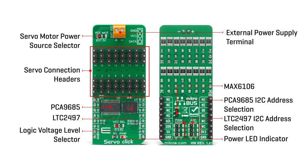
## Description: How Does The Servo Click Board™ Work? The Servo Click Board™ is based on the PCA9685, an integrated 12-bit 16-channel PWM driver which can be configured to either sink 25mA per channel or drive each channel sourcing up to 10mA from NXP. Each channel has its duty cycle independently set from 0% to 100%. Offering 16 independent channels, each with its own PWM duty cycle and current sensing ability, this Click board™ represents a powerful servo controller, especially useful when a large number of servos needs to be controlled simply and easily. The frequency of the control PWM signal can be programmed in the range from 24 Hz to 1526 Hz. The servo can be connected to any of the sixteen headers located on the Servo Click Board™. The output signal frequency is determined by the Prescaler value, which is written to the appropriate register. The output channels can be set either in the open-drain or in the push-pull configuration. In the first case, they will be able to sink up to 25mA from up to 5V power supply, while in the second case, they will be able to both drive with up to 10mA or sink up to 25mA. The Servo Click Board™ also has an accurate 16bit A/D converter the LTC2497 from Analog Devices used to sample the voltage drop across the shunt resistor on each of the 16 channels giving feedback on the servo current consumption. The ADC uses an accurate reference of 2.048V provided by an onboard reference voltage regulator MAX6106 from Maxim Integrated. An extremely low noise of this ADC coupled with a low reference voltage allows small voltage drops across the shunt resistor to be accurately converted. The Servo Click Board™ communicates with MCU using the standard I2C 2-Wire interface with a frequency up to 100kHz in the Standard, up to 400 kHz in the Fast, and up to 1MHz in the Fast-Plus mode. There are two more SMD jumpers, labelled as the PWM and ADC, located at the bottom of the Click board™ that allows selection of the slave I2C address for each of the two onboard ICs. It also has an external connector that can provide more power for servos that operate with heavier loads. That's why the SMD jumper labelled as VCC MOT should be at the EXT position. In this case, an external PSU that can provide more current can be used. The PCA9685 also offers Output Enable pin, routed to the mikroBUS™ CS pin, labelled as the OE. A LOW logic level on this pin will set all the outputs to the predefined logic state, turning the PWM generators OFF. This may either leave the servo into the fixed position or turn it down completely, depending on the servo model. The Servo Click Board™ is designed to be operated with both 3.3V and 5V logic voltage levels that can be selected via VCC SEL jumper. This allows for both 3.3V and 5V capable MCUs to use the I2C communication lines properly. SPECIFICATIONS Type Servo Applications The Servo Click Board™ can be used in applications when a large number of servos needs to be easily controlled in the movie or theater industry (animatronics), robotics, RC toys, and similar. On-board modules The Servo Click Board™ is based on the PCA9685, an integrated 12-bit 16-channel PWM driver which can be configured to either sink 25mA per channel or drive each channel sourcing up to 10mA from NXP. Key Features PWM driver with voltage sensing circuitry, programmable frequency, output enable and software reset feature, supports hot insertion, low standby current, and more. Interface I2C Compatibility mikroBUS Click board size L (57.15 x 25.4 mm) Input Voltage 3.3V or 5V PINOUT DIAGRAM This table shows how the pinout on the Servo Click Board™ corresponds to the pinout on the mikroBUS™ socket (the latter shown in the two middle columns). Notes Pin Pin Notes NC 1 AN PWM 16 NC NC 2 RST INT 15 NC Output Enable OE 3 CS RX 14 NC NC 4 SCK TX 13 NC NC 5 MISO SCL 12 SCL I2C Clock NC 6 MOSI SDA 11 SDA I2C Data Power supply 3.3V 7 3.3V 5V 10 5V Power supply Ground GND 8 GND GND 9 GND Ground ONBOARD SETTINGS AND INDICATORS Label Name Default Description LD1 PWR - Power LED indicator JP1 VCC SEL Left Power Supply Voltage Selection 3V3/5V: Left position 3V3, Right position 5V JP2 VCC MOT Left Servo Motor Power Source Selection: Left position External, Right position 5V JP3-JP5 PWM ADR Left PCA9685 I2C Address Selection: Left position 0, Right position 1 JP6-JP8 ADC ADR Left LTC2497 I2C Address Selection: Left position 0, Right position 1 HM1-HM16 1 - 16 - Servo Connection Headers SERVO CLICK ELECTRICAL SPECIFICATIONS Description Min Typ Max Unit Supply Voltage -0.5 - 6 V High Level Output Current -10 - +10 μA Low Level Output Current 12 25 - mA Total Power Dissipation - - 400 mW Operating Temperature Range -40 - +85 °C
## Product type: Click Board
## Vendor: Mikroelektronika d.o.o.
## Tags: Click Board, MikroE, Motor Control, NXP, Servo
## Price range: 28.0 - 28.0 GBP
## Link: https://thedebugstore.com/products/mikroe-3133-servo-click-board-uk
## Compare-at price range: 40.0 - 40.0 GBP
## Options
- Title: Default Title
## Collections
- [New Products](https://thedebugstore.com/a/llms/collections/new-products-debug-store)
- [Mikroelektronika d.o.o. (MikroE)](https://thedebugstore.com/a/llms/collections/mikroelektronika-catalogue-uk)
- [NXP Device Support from Debug Store: Explore Our Innovative Embedded Solutions](https://thedebugstore.com/a/llms/collections/nxp-device-support-uk)
- [Motor Control Click Boards™](https://thedebugstore.com/a/llms/collections/motor-control-click-boards-catalogue)
- [MikroE Click Boards™](https://thedebugstore.com/a/llms/collections/mikroe-click-boards-catalogue-uk)
- [Servo Motor Control Click Boards™](https://thedebugstore.com/a/llms/collections/servo-motor-control-click-boards-catalogue)
- [Click Boards™ Summer Sale](https://thedebugstore.com/a/llms/collections/inventory-sale)
- [MikroE Sale](https://thedebugstore.com/a/llms/collections/mikroe-sale)
- [MIKROE Stock](https://thedebugstore.com/a/llms/collections/mikroe-products-in-stock-sale)
## Variants
- Default Title, SKU: MIKROE-3133, Available: yes, Inventory: 1
## Metafields
- full_description: How Does The Servo Click Board™ Work?
The Servo Click Board™ is based on the PCA9685, an integrated 12-bit 16-channel PWM driver which can be configured to either sink 25mA per channel or drive each channel sourcing up to 10mA from NXP. Each channel has its duty cycle independently set from 0% to 100%. Offering 16 independent channels, each with its own PWM duty cycle and current sensing ability, this Click board™ represents a powerful servo controller, especially useful when a large number of servos needs to be controlled simply and easily. The frequency of the control PWM signal can be programmed in the range from 24 Hz to 1526 Hz.
The servo can be connected to any of the sixteen headers located on the Servo Click Board™. The output signal frequency is determined by the Prescaler value, which is written to the appropriate register. The output channels can be set either in the open-drain or in the push-pull configuration. In the first case, they will be able to sink up to 25mA from up to 5V power supply, while in the second case, they will be able to both drive with up to 10mA or sink up to 25mA.
The Servo Click Board™ also has an accurate 16bit A/D converter the LTC2497 from Analog Devices used to sample the voltage drop across the shunt resistor on each of the 16 channels giving feedback on the servo current consumption. The ADC uses an accurate reference of 2.048V provided by an onboard reference voltage regulator MAX6106 from Maxim Integrated. An extremely low noise of this ADC coupled with a low reference voltage allows small voltage drops across the shunt resistor to be accurately converted.
The Servo Click Board™ communicates with MCU using the standard I2C 2-Wire interface with a frequency up to 100kHz in the Standard, up to 400 kHz in the Fast, and up to 1MHz in the Fast-Plus mode. There are two more SMD jumpers, labelled as the PWM and ADC, located at the bottom of the Click board™ that allows selection of the slave I2C address for each of the two onboard ICs. It also has an external connector that can provide more power for servos that operate with heavier loads. That's why the SMD jumper labelled as VCC MOT should be at the EXT position. In this case, an external PSU that can provide more current can be used.
The PCA9685 also offers Output Enable pin, routed to the mikroBUS™ CS pin, labelled as the OE. A LOW logic level on this pin will set all the outputs to the predefined logic state, turning the PWM generators OFF. This may either leave the servo into the fixed position or turn it down completely, depending on the servo model.
The Servo Click Board™ is designed to be operated with both 3.3V and 5V logic voltage levels that can be selected via VCC SEL jumper. This allows for both 3.3V and 5V capable MCUs to use the I2C communication lines properly.
SPECIFICATIONS
| Type |
Servo |
| Applications |
The Servo Click Board™ can be used in applications when a large number of servos needs to be easily controlled in the movie or theater industry (animatronics), robotics, RC toys, and similar. |
| On-board modules |
The Servo Click Board™ is based on the PCA9685, an integrated 12-bit 16-channel PWM driver which can be configured to either sink 25mA per channel or drive each channel sourcing up to 10mA from NXP. |
| Key Features |
PWM driver with voltage sensing circuitry, programmable frequency, output enable and software reset feature, supports hot insertion, low standby current, and more. |
| Interface |
I2C |
| Compatibility |
mikroBUS |
| Click board size |
L (57.15 x 25.4 mm) |
| Input Voltage |
3.3V or 5V |
PINOUT DIAGRAM
This table shows how the pinout on the Servo Click Board™ corresponds to the pinout on the mikroBUS™ socket (the latter shown in the two middle columns).
| Notes |
Pin |
 |
Pin |
Notes |
| NC |
1 |
AN |
PWM |
16 |
NC |
| NC |
2 |
RST |
INT |
15 |
NC |
| Output Enable |
OE |
3 |
CS |
RX |
14 |
NC |
| NC |
4 |
SCK |
TX |
13 |
NC |
| NC |
5 |
MISO |
SCL |
12 |
SCL |
I2C Clock |
| NC |
6 |
MOSI |
SDA |
11 |
SDA |
I2C Data |
| Power supply |
3.3V |
7 |
3.3V |
5V |
10 |
5V |
Power supply |
| Ground |
GND |
8 |
GND |
GND |
9 |
GND |
Ground |
ONBOARD SETTINGS AND INDICATORS
| Label |
Name |
Default |
Description |
| LD1 |
PWR |
- |
Power LED indicator |
| JP1 |
VCC SEL |
Left |
Power Supply Voltage Selection 3V3/5V: Left position 3V3, Right position 5V |
| JP2 |
VCC MOT |
Left |
Servo Motor Power Source Selection: Left position External, Right position 5V |
| JP3-JP5 |
PWM ADR |
Left |
PCA9685 I2C Address Selection: Left position 0, Right position 1 |
| JP6-JP8 |
ADC ADR |
Left |
LTC2497 I2C Address Selection: Left position 0, Right position 1 |
| HM1-HM16 |
1 - 16 |
- |
Servo Connection Headers |
SERVO CLICK ELECTRICAL SPECIFICATIONS
| Description |
Min |
Typ |
Max |
Unit |
| Supply Voltage |
-0.5 |
- |
6 |
V |
| High Level Output Current |
-10 |
- |
+10 |
μA |
| Low Level Output Current |
12 |
25 |
- |
mA |
| Total Power Dissipation |
- |
- |
400 |
mW |
| Operating Temperature Range |
-40 |
- |
+85 |
°C |
- description_tag: Transform servo control with Servo Click Board™ - 16-Channel PWM precision. Buy from tested supplier - Debug Store. Click to upgrade now!
- title_tag: MikroE Servo Click Board™ (MIKROE-3133)
- manufacturer: Mikroelektronika d.o.o.
- warranty: 12 months
- amazon_enable: TRUE
- amazon_title: Servo Click Board
- amazon_product_type: computercomponent
- amazon_block: FALSE
- amazon_prime_enable: FALSE
- amazon_search: MikroElektronika Microelectronica MIKROE-1100
- amazon_uk_price: 22
- amazon_uk_currency: GBP
- amazon_de_currency: EUR
- amazon_de_price: 24.86
- amazon_fr_currency: EUR
- amazon_fr_price: 24.86
- amazon_es_currency: EUR
- amazon_es_price: 24.86
- amazon_nl_currency: EUR
- amazon_nl_price: 24.86
- amazon_it_currency: EUR
- amazon_it_price: 24.86
- amazon_se_curency: SEK
- amazon_se_price: 250.8
- amazon_product_id: 8606018713448
- amazon_product_id_type: EAN
- amazon_update: Update
- amazon_short_description: The Servo Click Board™ is a 16-channel PWM servo driver with the voltage sensing circuitry. It can be used to simultaneously control 16 servo motors, each with its own programmable PWM signal. The frequency of the control PWM signal can be programmed in the range from 24 Hz to 1526 Hz, which is an ideal range for driving various types of servos. An accurate 16bit A/D converter is used to sample the voltage drop across the shunt resistor on each of the 16 channels, giving feedback on the servo current consumption. This way, Servo click is able to provide an information about the servo operation parameters, with no additional modifications of the servo itself.
- amazon_long_description: Servo Click Board™ is a 16-channel PWM servo driver with the voltage sensing circuitry. It can be used to simultaneously control 16 servo motors, each with its own programmable PWM signal. The frequency of the control PWM signal can be programmed in the range from 24 Hz to 1526 Hz, which is an ideal range for driving various types of servos. An accurate 16-bit A/D converter is used to sample the voltage drop across the shunt resistor on each of the 16 channels, giving feedback on the servo current consumption. This way, Servo Click Board™ is able to provide an information about the servo operation parameters, with no additional modifications of the servo itself.
- amazon_main_image: https://www.thedebugstore.com/images/product/lg-servo-front_1.jpg
- amazon_other_image_1: https://www.thedebugstore.com/images/product/lg-servo-back_1.jpg
- amazon_other_image_2: https://www.thedebugstore.com/images/product/lg-servo-click-in-use_1.jpg
- amazon_other_image_3: https://www.thedebugstore.com/images/product/lg-servo-click-in-use_1.jpg
- amazon_browse_node: 428655031
- mpn: MIKROE-3133
- backorder_label: If no stock shown above, check availability
- google_product_category: 2082
- condition: new
- custom_product: false
- mpn: MIKROE-3133
- google_product_category: Electronics
- custom_label_0: Click Board
- examples: We provide a demo application for the Servo Click Board™ on our Libstock page, as well as a demo application (example), developed using MikroElektronika compilers. The demo can run on all the main MikroElektronika development boards.
Library Description
This library will allow you to control multiple servo motors at once.
Key Functions
void servo_init(uint8_t minPosition, uint8_t maxPosition, uint16_t lowResolution, uint16_t highResolution); - Main click board initialization routine.void servo_setMode(uint8_t mode,uint8_t _data); - Set's the operation mode of the click board.servo_sleep(); - The function needs to be set before setting the frequency.void servo_setFREQ(uint16_t freq); - Used for setting the frequency.void servo_setPosition(uint8_t motor, uint8_t position); - Set the position of the selected servo motor.
Example Description
The application is composed of three sections:
- System Initialization - Initializes the I2C module and the CS pin as the output
- Application Initialization - Initializes the driver and the servo (setting the minimum and maximum servo motors position and resolutions). Default resolution is 1ms. The IC is set to Sleep mode in order to set the frequency, after which the working mode of the servo is set
- Application Task - (code snippet) - The servo motor is moved across three different positions: 0, 90, 180 - every two seconds. The current consumption is sampled while the servo transitions between these points
void applicationTask()
{
 servo_setPosition(_SERVO_MOTOR_1, 0);
 Delay_ms( 2000 );
 servo_setPosition(_SERVO_MOTOR_1, 90);
 Delay_ms( 1000 );
 servo_setPosition(_SERVO_MOTOR_1, 180);
 Delay_ms( 2000 );
 servo_setPosition(_SERVO_MOTOR_1, 90);
 Current = setvo_getCurrent(_SERVO_POSITIVE_CH0);
 IntToStr(Current , text);
 mikrobus_logWrite( "Current - ", _LOG_TEXT );
 mikrobus_logWrite( text, _LOG_TEXT );
 mikrobus_logWrite( " mA", _LOG_LINE );
 Delay_ms( 1000 );
}
The full application code, and ready to use projects can be found on our Libstock page.
Other MikroElektronika libraries used in the example:
- I2C Library
- UART Library
- Conversions Library
- C_String Library
ADDITIONAL NOTES AND INFORMATION
Depending on the development board you are using, you may need a USB UART click, USB UART 2 click or RS232 click to connect to your PC, for development systems with no UART to USB interface available on the board. The terminal available in all MikroElektronika compilers, or any other terminal application of your choice, can be used to read the message.
MIKROSDK
The Servo Click Board™ is supported with mikroSDK - MikroElektronika Software Development Kit. To ensure proper operation of mikroSDK compliant click board demo applications, mikroSDK should be downloaded from the LibStock and installed for the compiler you are using.
- attachments: [[],[],[],[]]
- device_vendor: Linear Technology, Maxim Integrated, NXP Semiconductors
- device_type: LTC2497CUHF#PBF, MAX6106EUR+T, PCA9685PW/Q900,118
- warranty: 12 months
- brand: MikroE
- manufacturer: Mikroelektronika d.o.o.
- badge: No reviews
- widget:
- brands: gid://shopify/Metaobject/56256004319
- breadcrumbs: ["gid://shopify/Collection/447955239135","gid://shopify/Collection/241680580797","gid://shopify/Collection/241545248957","gid://shopify/Collection/279405297853"]
- customhs_code: 847330
- detailed_description: {"type":"root","children":[{"type":"heading","level":3,"children":[{"type":"text","value":"How Does The Servo Click Board™"},{"type":"text","value":" ","bold":true},{"type":"text","value":"Work?"}]},{"type":"paragraph","children":[{"type":"text","value":"The "},{"type":"text","value":"Servo Click Board™","bold":true},{"type":"text","value":" is based on the PCA9685, an integrated 12-bit 16-channel PWM driver which can be configured to either sink 25mA per channel or drive each channel sourcing up to 10mA from NXP. Each channel has its duty cycle independently set from 0% to 100%. Offering 16 independent channels, each with its own PWM duty cycle and current sensing ability, this Click board™ represents a powerful servo controller, especially useful when a large number of servos needs to be controlled simply and easily. The frequency of the control PWM signal can be programmed in the range from 24 Hz to 1526 Hz."}]},{"type":"paragraph","children":[{"type":"text","value":""}]},{"type":"paragraph","children":[{"type":"text","value":"The servo can be connected to any of the sixteen headers located on the "},{"type":"text","value":"Servo Click Board™","bold":true},{"type":"text","value":". The output signal frequency is determined by the Prescaler value, which is written to the appropriate register. The output channels can be set either in the open-drain or in the push-pull configuration. In the first case, they will be able to sink up to 25mA from up to 5V power supply, while in the second case, they will be able to both drive with up to 10mA or sink up to 25mA."}]},{"type":"paragraph","children":[{"type":"text","value":"The "},{"type":"text","value":"Servo Click Board™","bold":true},{"type":"text","value":" also has an accurate 16bit A/D converter the LTC2497 from Analog Devices used to sample the voltage drop across the shunt resistor on each of the 16 channels giving feedback on the servo current consumption. The ADC uses an accurate reference of 2.048V provided by an onboard reference voltage regulator MAX6106 from Maxim Integrated. An extremely low noise of this ADC coupled with a low reference voltage allows small voltage drops across the shunt resistor to be accurately converted."}]},{"type":"paragraph","children":[{"type":"text","value":"The "},{"type":"text","value":"Servo Click Board™","bold":true},{"type":"text","value":" communicates with MCU using the standard I2C 2-Wire interface with a frequency up to 100kHz in the Standard, up to 400 kHz in the Fast, and up to 1MHz in the Fast-Plus mode. There are two more SMD jumpers, labelled as the PWM and ADC, located at the bottom of the Click board™ that allows selection of the slave I2C address for each of the two onboard ICs. It also has an external connector that can provide more power for servos that operate with heavier loads. That's why the SMD jumper labelled as VCC MOT should be at the EXT position. In this case, an external PSU that can provide more current can be used."}]},{"type":"paragraph","children":[{"type":"text","value":"The PCA9685 also offers Output Enable pin, routed to the mikroBUS™ CS pin, labelled as the OE. A LOW logic level on this pin will set all the outputs to the predefined logic state, turning the PWM generators OFF. This may either leave the servo into the fixed position or turn it down completely, depending on the servo model."}]},{"type":"paragraph","children":[{"type":"text","value":"The "},{"type":"text","value":"Servo Click Board™","bold":true},{"type":"text","value":" is designed to be operated with both 3.3V and 5V logic voltage levels that can be selected via VCC SEL jumper. This allows for both 3.3V and 5V capable MCUs to use the I2C communication lines properly."}]},{"type":"heading","level":3,"children":[{"type":"text","value":"SPECIFICATIONS"}]},{"type":"paragraph","children":[{"type":"text","value":"Type\nServo\nApplications\nThe Servo Click Board™ can be used in applications when a large number of servos needs to be easily controlled in the movie or theater industry (animatronics), robotics, RC toys, and similar.\nOn-board modules\nThe Servo Click Board™ is based on the PCA9685, an integrated 12-bit 16-channel PWM driver which can be configured to either sink 25mA per channel or drive each channel sourcing up to 10mA from NXP.\nKey Features\nPWM driver with voltage sensing circuitry, programmable frequency, output enable and software reset feature, supports hot insertion, low standby current, and more.\nInterface\nI2C\nCompatibility\nmikroBUS\nClick board size\nL (57.15 x 25.4 mm)\nInput Voltage\n3.3V or 5V"}]},{"type":"heading","level":3,"children":[{"type":"text","value":"PINOUT DIAGRAM"}]},{"type":"paragraph","children":[{"type":"text","value":"This table shows how the pinout on the "},{"type":"text","value":"Servo Click Board™","bold":true},{"type":"text","value":" corresponds to the pinout on the mikroBUS™ socket (the latter shown in the two middle columns)."}]},{"type":"paragraph","children":[{"type":"text","value":"Notes\nPin\nPin\nNotes\nNC\n1\nAN\nPWM\n16\nNC\nNC\n2\nRST\nINT\n15\nNC\nOutput Enable\nOE\n3\nCS\nRX\n14\nNC\nNC\n4\nSCK\nTX\n13\nNC\nNC\n5\nMISO\nSCL\n12\nSCL\nI2C Clock\nNC\n6\nMOSI\nSDA\n11\nSDA\nI2C Data\nPower supply\n3.3V\n7\n3.3V\n5V\n10\n5V\nPower supply\nGround\nGND\n8\nGND\nGND\n9\nGND\nGround"}]},{"type":"heading","level":3,"children":[{"type":"text","value":""},{"type":"text","value":"ONBOARD SETTINGS AND INDICATORS"}]},{"type":"paragraph","children":[{"type":"text","value":"Label\nName\nDefault\nDescription\nLD1\nPWR\n-\nPower LED indicator\nJP1\nVCC SEL\nLeft\nPower Supply Voltage Selection 3V3/5V: Left position 3V3, Right position 5V\nJP2\nVCC MOT\nLeft\nServo Motor Power Source Selection: Left position External, Right position 5V\nJP3-JP5\nPWM ADR\nLeft\nPCA9685 I2C Address Selection: Left position 0, Right position 1\nJP6-JP8\nADC ADR\nLeft\nLTC2497 I2C Address Selection: Left position 0, Right position 1\nHM1-HM16\n1 - 16\n-\nServo Connection Headers"}]},{"type":"heading","level":3,"children":[{"type":"text","value":"SERVO CLICK ELECTRICAL SPECIFICATIONS"}]},{"type":"paragraph","children":[{"type":"text","value":"Description\nMin\nTyp\nMax\nUnit\nSupply Voltage\n-0.5\n-\n6\nV\nHigh Level Output Current\n-10\n-\n+10\nμA\nLow Level Output Current\n12\n25\n-\nmA\nTotal Power Dissipation\n-\n-\n400\nmW\nOperating Temperature Range\n-40\n-\n+85\n°C"}]},{"type":"heading","level":3,"children":[{"type":"text","value":" "}]}]}
- summary: Introducing the Servo Click Board™: Revolutionize Your Servo Control
Are you tired of struggling with limited servo control options? Look no further! The Servo Click Board™ is here to transform your servo control experience.
Unleash the Power of 16-Channel PWM Control
Say goodbye to single-channel limitations. With the Servo Click Board™, you can simultaneously control a whopping 16 servo motors! Each servo enjoys its own programmable PWM signal, giving you unparalleled flexibility and precision in your projects.
Fine-Tune Your Servo Performance
Precision matters. That's why we equipped the Servo Click Board™ with a programmable PWM signal frequency range from 24 Hz to 1526 Hz. This range is meticulously chosen to cater to various servo types, ensuring that your creations move with the utmost precision and accuracy.
Real-Time Insights with Voltage Sensing
What sets the Servo Click Board™ apart is its 16-bit A/D converter, which samples the voltage drop across each channel's shunt resistor. This means you get real-time feedback on servo current consumption, allowing you to optimize performance and prevent overheating without any need for modifying your servos.
Why Choose the Servo Click Board™?
-
Effortless Control: Control up to 16 servos with ease, streamlining your projects and saving you time.
-
Precision in Every Move: Fine-tune your servos to perfection with a wide PWM signal frequency range.
-
Protect Your Servos: Monitor current consumption in real-time to prevent damage and enhance longevity.
Make the smart choice and experience a new level of servo control with the Servo Click Board™. Elevate your projects, unlock limitless possibilities, and join the ranks of satisfied customers who have already made the switch.
Ready to revolutionize your servo control? Click the button below and take the first step towards a brighter, more precise future!
Get Your Servo Click Board™ Now
Don't miss out on this game-changing innovation. Upgrade your servo control today!