The RS232 communication standard is established back in the '60s, but thanks to its implementation on a wide range of devices - including PC motherboards, it gained a lot of popularity and it is still in use. Over time, this standard went through many revisions and the most recent revision is TIA-232-F (R2012). Although it was originally developed to connect teletypewriters and modems, nowadays it is used for serial communication between a wide array of different devices.
To implement the RS232 communication standard on the MCUs, it is necessary to convert the voltage levels to the levels acceptable for the modern MCUs. The RS232 2 Click Board™ performs full RS232 to UART signal conversion, allowing both 3.3V and 5V operation. Additionally, it features ±15 kV ESD protection for the RS-232 I/O pins. These attributes make this click a perfect solution for battery powered, hand-held and portable equipment, PDAs, palmtops, digital cameras, and other devices that still support the RS232 standard.
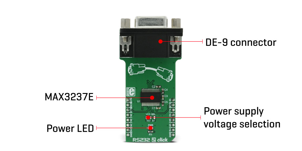
The integrated circuit used to provide an electrical interface between RS232 and UART on the RS232 2 click is the MAX3237E, a 3V to 5.5V multichannel RS232, 1 Mbit/s line driver/receiver from Texas Instruments. This device allows communication at 1 Mbit/s and allows 5V logic levels, even when working with 3.3V power supply. However, there is an onboard SMD jumper that allows selection of power supply voltage between 3.3V and 5V, if there is a requirement.
The MAX3237E IC consists of five line drivers, three line receivers, and a dual charge pump circuit with ±15 kV pin to pin ESD protection for the serial port I/O pins. Those charge pumps along with the external capacitors, allow the device to run from a single 3V to 5.5V supply, providing the required RS232 voltage levels, which can go up to ±15 V as per standard. The MAX3237E IC generates an RS232 voltage in the range of ±13 V and accepts RS232 signal levels in the range of ±25 V.
To provide the minimal functionality of the UART interface, at least three data lines have to be used: RX line, routed to the mikroBUS™ RX pin (on the click board side), TX line, routed to the mikroBUS™ TX pin (on the click board side), and the GND. Otherwise, this device supports the full stack of RS232 control lines, excluding the Data Set Ready line (DSR). Other relevant RS232 bus lines routed to the mikroBUS™ pins are: Data Terminal Ready (DTR) - routed to the AN pin, Data Carrier Detect (DCD) - routed to the RST pin, Clear To Send (CTS) - routed to the CS pin, Ring Indicator (RI) - routed to the PWM pin, Request To Send (RTS) - routed to the INT pin. All these lines, are actually control lines and are used optionally by the RS232 device.
The RS232 2 Click Board™ features the standardized DE-9 connector for easy connection to the RS232 device. By switching the VCC SEL jumper, it is possible to select the power supply voltage for the RS232 2 click. Although it can work with 5V, the device will accept UART signals of 5V even while working in 3.3V mode.
| Type | RS232 |
| Applications | The RS232 2 Click Board™ is a perfect solution for battery powered hand-held and portable equipment, PDAs, palmtops, digital cameras, and other devices that still support the RS232 standard. |
| On-board modules | MAX3237E, a 3.3V or 5V multichannel RS232, 1 Mbit/s line driver/receiver from Texas Instruments |
| Key Features | RS232 2 click allows easy and reliable RS232 to UART communication. It requires 3.3V or 5V for the proper operation and provides RS232 line levels directly, without using any additional components. RS232 I/O pins are ESD protected for up to 15kV. |
| Interface | GPIO,UART |
| Compatibility | mikroBUS |
| Click board size | L (57.15 x 25.4 mm) |
| Input Voltage | 3.3V or 5V |
This table shows how the pinout of the RS232 2 Click Board™ corresponds to the pinout on the mikroBUS™ socket (the latter shown in the two middle columns).
| Notes | Pin | Pin | Notes | ||||
|---|---|---|---|---|---|---|---|
| Ready to Receive | DTR | 1 | AN | PWM | 16 | RI | Ring Indication |
| Carrier Receiving Indication | DCD | 2 | RST | INT | 15 | RTS | Ready to Send |
| Clear to Send | CTS | 3 | CS | RX | 14 | TX | UART Transmit |
| NC | 4 | SCK | TX | 13 | RX | UART Receive | |
| NC | 5 | MISO | SCL | 12 | NC | ||
| NC | 6 | MOSI | SDA | 11 | NC | ||
| Power Supply | +3.3V | 7 | 3.3V | 5V | 10 | +5V | Power Supply |
| Ground | GND | 8 | GND | GND | 9 | GND | Ground |
| Description | Min | Typ | Max | Unit |
|---|---|---|---|---|
| Input Voltage Range on RS232 | -25 | +25 | V | |
| Output Voltage Range on RS232 | -13 | +13 | V | |
| Data Rate | 250 | 1000 | kbps |
| Label | Name | Default | Description |
|---|---|---|---|
| LD1 | PWR | - | Power LED indicator |
| JP1 | VCC SEL | Left | Voltage level selection, left position 3.3V, right 5V |
The RS232 communication standard is established back in the 1960s, but thanks to its implementation on a wide range of devices - including PC motherboards, it gained a lot of popularity and it is still in use. Over time, this standard went through many revisions and the most recent revision is TIA-232-F (R2012). Although it was riginally developed to connect teletypewriters and modems, nowadays it is used for serial communication between a wide array of different devices.
To implement the RS232 communication standard on the MCUs, it is necessary to convert the voltage levels to the levels acceptable for the modern MCUs. RS232 2 Click performs full RS232 to UART signal conversion, allowing both 3.3V and 5V operation. Additionally, it features ±15 kV ESD protection for the RS-232 I/O pins. These attributes make this Click a perfect solution for battery powered, hand-held and portable equipment, PDAs, palmtops, digital cameras, and other devices that still support the RS232 standard.
The integrated circuit used to provide an electrical interface between RS232 and UART on the RS232 2 Click is the MAX3237E, a 3V to 5.5V multichannel RS232, 1 Mbit/s line driver/receiver from Texas Instruments. This device allows communication at 1 Mbit/s and allows 5V logic levels, even when working with 3.3V power supply. However, there is an on-board SMD jumper that allows selection of power supply voltage between 3.3V and 5V, if there is a requirement.
The MAX3237E IC consists of five line drivers, three line receivers, and a dual charge pump circuit with ±15 kV pin to pin ESD protection for the serial port I/O pins. Those charge pumps along with the external capacitors, allow the device to run from a single 3V to 5.5V supply, providing the required RS232 voltage levels, which can go up to ±15 V as per standard. The MAX3237E IC generates an RS232 voltage in the range of ±13 V and accepts RS232 signal levels in the range of ±25 V.
To provide the minimal functionality of the UART interface, at least three data lines have to be used: RX line, routed to the mikroBUS RX pin (on the Click Board™ side), TX line, routed to the mikroBUS TX pin (on the Click Board™ side), and the GND. Otherwise, this device supports the full stack of RS232 control lines, excluding the Data Set Ready line (DSR). Other relevant RS232 bus lines routed to the mikroBUS pins are: Data Terminal Ready (DTR) - routed to the AN pin, Data Carrier Detect (DCD) - routed to the RST pin, Clear To Send (CTS) - routed to the CS pin, Ring Indicator (RI) - routed to the PWM pin, Request To Send (RTS) - routed to the INT pin. All these lines, are actually control lines and are used optionally by the RS232 device.
RS232 2 Click features the standardized DE-9 connector for easy connection to the RS232 device. By switching the VCC SEL jumper, it is possible to select the power supply voltage for the RS232 2 Click. Although it can work with 5V, the device will accept UART signals of 5V even while working in 3.3V mode.
- amazon_main_image: https://www.thedebugstore.com/images/product/lg-rs232-2-click-board.jpg - amazon_browse_node: 428655031 - mpn: MIKROE-2897 - backorder_label: If no stock shown above, check availability - badge: - widget:We provide a library for the RS232 2 Click Board™ on our LibStock page, as well as a demo application (example), developed using MikroElektronika compilers and mikroSDK. The provided click library is mikroSDK standard compliant. The demo application can run on all the main MikroElektronika development boards.
This library carries functions for data transmission and reception alongside with functions for individual control of each GPIO pin found on the RS232 2 Click Board™.
Key functions
uint8_t rs232_2_readByte()- Reads received byte
void rs232_2_writeByte(uint8_t input)- Sends byte
uint8_t rs232_2_byteReady()-Checks for received byte
Examples Description
The application is composed of three sections :
void applicationTask()
{
// RECEIVER
#ifdef __RX__
 if (rs232_2_byteReady())
 {
 rec = rs232_2_readByte();
 mikrobus_logWrite( &rec, _LOG_BYTE );
 }
#endif
// TRANSMITER
#ifdef __TX__
 for (tmp = 0; tmp < 9; tmp++)
 {
 rs232_2_writeByte( MESSAGE_DATA[tmp] );
 }
 Delay_ms(2000);
#endif
}
The full application code, and ready to use projects can be found on our LibStock page.
MikroElektronika Libraries used in the example:
Depending on the development board you are using, you may need a USB UART click, USB UART 2 click or RS232 click to connect to your PC, for development systems with no UART to USB interface available on the board. The terminal available in all MikroElektronika compilers, or any other terminal application of your choice, can be used to read the message.
The RS232 2 Click Board™ is supported with mikroSDK - MikroElektronika Software Development Kit. To ensure proper operation of mikroSDK compliant click board demo applications, mikroSDK should be downloaded from the LibStock and installed for the compiler you are using.
- attachments: [{"download_file":[{"download_file":"RS232 2 Click Board™ Schematic"}],"download_filetype":[{"download_filetype":"pdf"}]},{"download_file":[{"download_file":"Texas Instruments MAX3237E 3V to 5V RS-232 Transmitter/Receiver Datasheet"}],"download_filetype":[{"download_filetype":"pdf"}]}] - device_vendor: Texas Instruments - device_type: MAX3237EIDBR - warranty: 12 months - brand: MikroE - manufacturer: Mikroelektronika d.o.o. - brands: gid://shopify/Metaobject/56256004319 - breadcrumbs: ["gid://shopify/Collection/447955239135","gid://shopify/Collection/241680580797","gid://shopify/Collection/241546100925"] - customhs_code: 847330 - detailed_description: {"type":"root","children":[{"type":"paragraph","children":[{"type":"text","value":"The RS232 communication standard is established back in the '60s, but thanks to its implementation on a wide range of devices - including PC motherboards, it gained a lot of popularity and it is still in use. Over time, this standard went through many revisions and the most recent revision is TIA-232-F (R2012). Although it was originally developed to connect teletypewriters and modems, nowadays it is used for serial communication between a wide array of different devices."}]},{"type":"paragraph","children":[{"type":"text","value":"To implement the RS232 communication standard on the MCUs, it is necessary to convert the voltage levels to the levels acceptable for the modern MCUs. The RS232 2 Click Board™ performs full RS232 to UART signal conversion, allowing both 3.3V and 5V operation. Additionally, it features ±15 kV ESD protection for the RS-232 I/O pins. These attributes make this click a perfect solution for battery powered, hand-held and portable equipment, PDAs, palmtops, digital cameras, and other devices that still support the RS232 standard."}]},{"type":"heading","level":3,"children":[{"type":"text","value":"How Does The RS232 2 Click Board™ Work?"}]},{"type":"paragraph","children":[{"type":"text","value":"The integrated circuit used to provide an electrical interface between RS232 and UART on the RS232 2 click is the MAX3237E, a 3V to 5.5V multichannel RS232, 1 Mbit/s line driver/receiver from Texas Instruments. This device allows communication at 1 Mbit/s and allows 5V logic levels, even when working with 3.3V power supply. However, there is an onboard SMD jumper that allows selection of power supply voltage between 3.3V and 5V, if there is a requirement."}]},{"type":"paragraph","children":[{"type":"text","value":"The MAX3237E IC consists of five line drivers, three line receivers, and a dual charge pump circuit with ±15 kV pin to pin ESD protection for the serial port I/O pins. Those charge pumps along with the external capacitors, allow the device to run from a single 3V to 5.5V supply, providing the required RS232 voltage levels, which can go up to ±15 V as per standard. The MAX3237E IC generates an RS232 voltage in the range of ±13 V and accepts RS232 signal levels in the range of ±25 V."},{"type":"text","value":""},{"type":"text","value":""},{"type":"text","value":""}]},{"type":"paragraph","children":[{"type":"text","value":"To provide the minimal functionality of the UART interface, at least three data lines have to be used: RX line, routed to the mikroBUS™ RX pin (on the click board side), TX line, routed to the mikroBUS™ TX pin (on the click board side), and the GND. Otherwise, this device supports the full stack of RS232 control lines, excluding the Data Set Ready line (DSR). Other relevant RS232 bus lines routed to the mikroBUS™ pins are: Data Terminal Ready (DTR) - routed to the AN pin, Data Carrier Detect (DCD) - routed to the RST pin, Clear To Send (CTS) - routed to the CS pin, Ring Indicator (RI) - routed to the PWM pin, Request To Send (RTS) - routed to the INT pin. All these lines, are actually control lines and are used optionally by the RS232 device."}]},{"type":"paragraph","children":[{"type":"text","value":"The "},{"type":"text","value":"RS232 2 Click Board™","bold":true},{"type":"text","value":" features the standardized DE-9 connector for easy connection to the RS232 device. By switching the VCC SEL jumper, it is possible to select the power supply voltage for the RS232 2 click. Although it can work with 5V, the device will accept UART signals of 5V even while working in 3.3V mode."}]},{"type":"heading","level":3,"children":[{"type":"text","value":"SPECIFICATIONS"}]},{"type":"paragraph","children":[{"type":"text","value":"Type\nRS232\nApplications\nThe RS232 2 Click Board™ is a perfect solution for battery powered hand-held and portable equipment, PDAs, palmtops, digital cameras, and other devices that still support the RS232 standard.\nOn-board modules\nMAX3237E, a 3.3V or 5V multichannel RS232, 1 Mbit/s line driver/receiver from Texas Instruments\nKey Features\nRS232 2 click allows easy and reliable RS232 to UART communication. It requires 3.3V or 5V for the proper operation and provides RS232 line levels directly, without using any additional components. RS232 I/O pins are ESD protected for up to 15kV.\nInterface\nGPIO,UART\nCompatibility\nmikroBUS\nClick board size\nL (57.15 x 25.4 mm)\nInput Voltage\n3.3V or 5V"}]},{"type":"heading","level":3,"children":[{"type":"text","value":"PINOUT DIAGRAM"}]},{"type":"paragraph","children":[{"type":"text","value":"This table shows how the pinout of the "},{"type":"text","value":"RS232 2 Click Board™","bold":true},{"type":"text","value":" corresponds to the pinout on the mikroBUS™ socket (the latter shown in the two middle columns)."}]},{"type":"paragraph","children":[{"type":"text","value":"Notes\nPin\nPin\nNotes\nReady to Receive\nDTR\n1\nAN\nPWM\n16\nRI\nRing Indication\nCarrier Receiving Indication\nDCD\n2\nRST\nINT\n15\nRTS\nReady to Send\nClear to Send\nCTS\n3\nCS\nRX\n14\nTX\nUART Transmit\nNC\n4\nSCK\nTX\n13\nRX\nUART Receive\nNC\n5\nMISO\nSCL\n12\nNC\nNC\n6\nMOSI\nSDA\n11\nNC\nPower Supply\n+3.3V\n7\n3.3V\n5V\n10\n+5V\nPower Supply\nGround\nGND\n8\nGND\nGND\n9\nGND\nGround"}]},{"type":"heading","level":3,"children":[{"type":"text","value":"RS232 2 CLICK ELECTRICAL SPECIFICATIONS"}]},{"type":"paragraph","children":[{"type":"text","value":"Description\nMin\nTyp\nMax\nUnit\nInput Voltage Range on RS232\n-25\n+25\nV\nOutput Voltage Range on RS232\n-13\n+13\nV\nData Rate\n250\n1000\nkbps"}]},{"type":"heading","level":3,"children":[{"type":"text","value":"ONBOARD SETTINGS AND INDICATORS"}]},{"type":"paragraph","children":[{"type":"text","value":"Label\nName\nDefault\nDescription\nLD1\nPWR\n-\nPower LED indicator\nJP1\nVCC SEL\nLeft\nVoltage level selection, left position 3.3V, right 5V"}]},{"type":"heading","level":3,"children":[{"type":"text","value":" "}]}]} - summary:To implement the RS232 communication standard on the MCUs, it is necessary to convert the voltage levels to the levels acceptable for the modern MCUs. The RS232 2 Click Board™ performs full RS232 to UART signal conversion, allowing both 3.3V and 5V operation. Additionally, it features 15 kV ESD protection for the RS-232 I/O pins.
These attributes make the RS232 2 Click Board™ a perfect solution for battery-powered, hand-held and portable equipment, PDAs, palmtops, digital cameras, and other devices that still support the RS-232 standard.