# Title: ADC 5 Click Board™
## Description: The features such as the low power consumption, two operational modes used to fine-tune the overall performance vs power consumption, consistency over a wide range of sampling frequencies, industry-standard SPI communication interface, make this device a perfect solution for using it in various applications which depend on linear and accurate analogue-to-digital conversion, such as the instrumentation and control applications, conversion of the analogue data from various sensors, remote data acquisition, and similar. How Does The ADC 5 Click Board™ Work? The ADC 5 Click Board™ is equipped with the ADC121S021, a 12-bit CMOS ADC device from Texas Instruments. This AD converter is using a reference voltage obtained from the LP2985 LDO regulator from the same company, which provides a clean and accurate regulated voltage on its output, perfectly suited to be used as the reference voltage for this converter. Since the reference voltage is set to 3.3V, the maximum value of the input voltage is also 3.3V. The device uses SPI communication. The MOSI pin does not exist, since no communication from the MCU to the click board™ is going on. The reading speed, also known as the sample rate, directly depends on the clock rate of the SCK line. The sample rate over which the specified electrical performance is ensured is 50 Ks/s to 200 Ks/s. The ADC121S021 has the ability to use any clock signal frequency up to the rated maximum frequency, with no significant deviations from the specifications stated in the datasheet: it is specified over a wide range of sample rates, maintaining good linearity and high signal to noise ratio (SNR). In general, ADC (analogue to digital converters) are the most commonly used devices for converting voltage signals into information, which can be then processed in the digital domain. There are many types of ADC converters commercially available. They can vary in bit depth, sample rate, used approximation algorithm (SAR, delta-sigma...) and so on. Those attributes affect how accurately the sampled voltage will be translated into the digital world. The sample rate is usually the determining factor when the maximum frequency of the input signal is considered. The aliasing of the input signal can occur as the input signal frequency is nearing half the sample rate of the converter. The bandwidth of the input signal is limited by this frequency, also called the Nyquist frequency, so using input frequencies near or above the Nyquist frequency, results in a very inaccurate conversion. The ADC121S021 AD converter uses the SAR, or the successive approximation method for the conversion, which consists of comparing the input voltage with a series of internally generated voltage values. At each step in this process, the approximation is stored in a successive approximation register. The comparing steps are continued until the desired resolution is reached. The ADC 5 Click Board™ is also equipped with the screw terminal which can be used for easy and secure connection of the input voltage rail. Although the reference voltage is 3.3V, it is powered only by the 5V rail from the mikroBUS™, used as the input for the LDO regulator. Specifications Type ADC Applications The ADC 5 Click Board™ can be used to digitally convert input voltage signals up to 3.3V so that the signals can be analysed by various algorithms on the CPU or a MCU. On-board modules ADC121S021 a single channel, 50ks/s to 200Ks/s, a 12-Bit SAR ADC, LP2950 - micropower voltage regulator with low voltage drop, both made by Texas Instruments. Key Features The ADC 5 Click Board™ specified to work with sample rates from 50Ks/s to 200Ks/s. It uses a precise LDO as a reference voltage source and SAR approximation method of sampling Interface SPI Compatibility mikroBUS Click board size M (42.9 x 25.4 mm) Input Voltage 5V Pinout diagram This table shows how the pinout on the ADC 5 Click Board™ corresponds to the pinout on the mikroBUS™ socket (the latter shown in the two middle columns). Notes Pin Pin Notes NC 1 AN PWM 16 NC NC 2 RST INT 15 NC SPI Chip Select CS 3 CS RX 14 NC SPI Clock SCK 4 SCK TX 13 NC SPI Data OUT SDO 5 MISO SCL 12 NC NC 6 MOSI SDA 11 NC NC 7 3.3V 5V 10 +5V Power supply Ground GND 8 GND GND 9 GND Ground ADC 5 click electrical specifications Description Min Typ Max Unit Vin (analogue input) 0 3.3 V ADC reference voltage 3.3 V Onboard settings and indicators Label Name Default Description PWR PWR - Power LED indicator TB1 TB1 - Analog input terminal
## Product type: Click Board
## Vendor: Mikroelektronika d.o.o.
## Tags: ADC, ADC Click, Click Board, MikroE, Mixed Signal
## Price range: 15.4 - 15.4 GBP
## Link: https://thedebugstore.com/products/mikroe-2846-adc-5-click-board-uk
## Compare-at price range: 22.0 - 22.0 GBP
## Options
- Title: Default Title
## Collections
- [New Products](https://thedebugstore.com/a/llms/collections/new-products-debug-store)
- [Mikroelektronika d.o.o. (MikroE)](https://thedebugstore.com/a/llms/collections/mikroelektronika-catalogue-uk)
- [Mixed Signal Click Boards™](https://thedebugstore.com/a/llms/collections/mixed-signal-click-boards-catalogue-uk)
- [MikroE Click Boards™](https://thedebugstore.com/a/llms/collections/mikroe-click-boards-catalogue-uk)
- [ADC Click Boards™](https://thedebugstore.com/a/llms/collections/adc-click-boards-catalogue-uk)
- [Click Boards™ Summer Sale](https://thedebugstore.com/a/llms/collections/inventory-sale)
- [MikroE Sale](https://thedebugstore.com/a/llms/collections/mikroe-sale)
- [MIKROE Stock](https://thedebugstore.com/a/llms/collections/mikroe-products-in-stock-sale)
## Variants
- Default Title, SKU: MIKROE-2846, Available: yes, Inventory: 1
## Metafields
- full_description: The features such as the low power consumption, two operational modes used to fine-tune the overall performance vs power consumption, consistency over a wide range of sampling frequencies, industry-standard SPI communication interface, make this device a perfect solution for using it in various applications which depend on linear and accurate analogue-to-digital conversion, such as the instrumentation and control applications, conversion of the analogue data from various sensors, remote data acquisition, and similar.
How Does The ADC 5 Click Board™ Work?
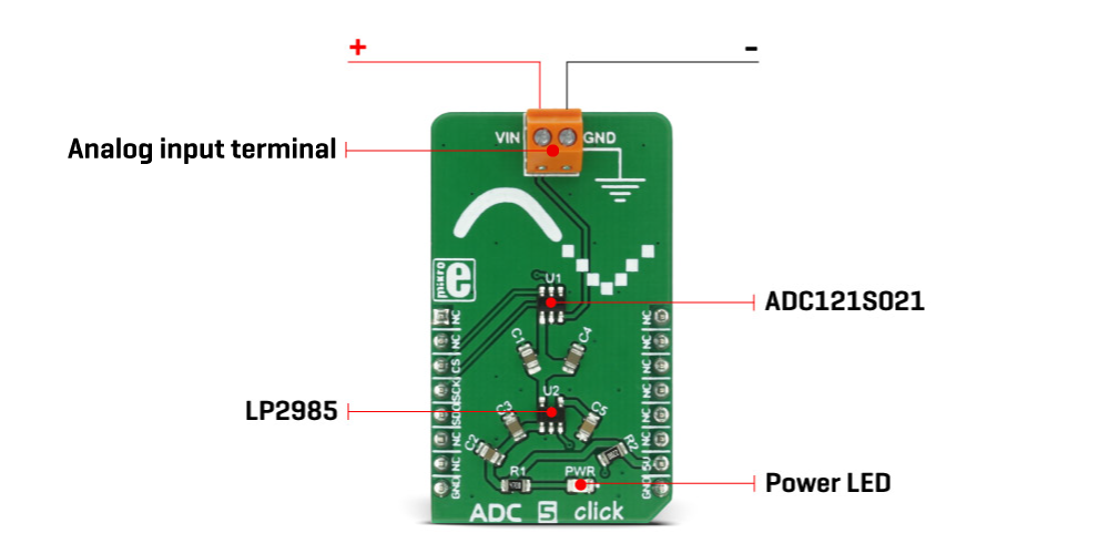
The ADC 5 Click Board™ is equipped with the ADC121S021, a 12-bit CMOS ADC device from Texas Instruments. This AD converter is using a reference voltage obtained from the LP2985 LDO regulator from the same company, which provides a clean and accurate regulated voltage on its output, perfectly suited to be used as the reference voltage for this converter. Since the reference voltage is set to 3.3V, the maximum value of the input voltage is also 3.3V.
The device uses SPI communication. The MOSI pin does not exist, since no communication from the MCU to the click board™ is going on. The reading speed, also known as the sample rate, directly depends on the clock rate of the SCK line. The sample rate over which the specified electrical performance is ensured is 50 Ks/s to 200 Ks/s. The ADC121S021 has the ability to use any clock signal frequency up to the rated maximum frequency, with no significant deviations from the specifications stated in the datasheet: it is specified over a wide range of sample rates, maintaining good linearity and high signal to noise ratio (SNR).
In general, ADC (analogue to digital converters) are the most commonly used devices for converting voltage signals into information, which can be then processed in the digital domain. There are many types of ADC converters commercially available. They can vary in bit depth, sample rate, used approximation algorithm (SAR, delta-sigma...) and so on. Those attributes affect how accurately the sampled voltage will be translated into the digital world.
The sample rate is usually the determining factor when the maximum frequency of the input signal is considered. The aliasing of the input signal can occur as the input signal frequency is nearing half the sample rate of the converter. The bandwidth of the input signal is limited by this frequency, also called the Nyquist frequency, so using input frequencies near or above the Nyquist frequency, results in a very inaccurate conversion.
The ADC121S021 AD converter uses the SAR, or the successive approximation method for the conversion, which consists of comparing the input voltage with a series of internally generated voltage values. At each step in this process, the approximation is stored in a successive approximation register. The comparing steps are continued until the desired resolution is reached.
The ADC 5 Click Board™ is also equipped with the screw terminal which can be used for easy and secure connection of the input voltage rail. Although the reference voltage is 3.3V, it is powered only by the 5V rail from the mikroBUS™, used as the input for the LDO regulator.
Specifications
| Type |
ADC |
| Applications |
The ADC 5 Click Board™ can be used to digitally convert input voltage signals up to 3.3V so that the signals can be analysed by various algorithms on the CPU or a MCU. |
| On-board modules |
ADC121S021 a single channel, 50ks/s to 200Ks/s, a 12-Bit SAR ADC, LP2950 - micropower voltage regulator with low voltage drop, both made by Texas Instruments. |
| Key Features |
The ADC 5 Click Board™ specified to work with sample rates from 50Ks/s to 200Ks/s. It uses a precise LDO as a reference voltage source and SAR approximation method of sampling |
| Interface |
SPI |
| Compatibility |
mikroBUS |
| Click board size |
M (42.9 x 25.4 mm) |
| Input Voltage |
5V |
Pinout diagram
This table shows how the pinout on the ADC 5 Click Board™ corresponds to the pinout on the mikroBUS™ socket (the latter shown in the two middle columns).
| Notes |
Pin |
 |
Pin |
Notes |
| NC |
1 |
AN |
PWM |
16 |
NC |
| NC |
2 |
RST |
INT |
15 |
NC |
| SPI Chip Select |
CS |
3 |
CS |
RX |
14 |
NC |
| SPI Clock |
SCK |
4 |
SCK |
TX |
13 |
NC |
| SPI Data OUT |
SDO |
5 |
MISO |
SCL |
12 |
NC |
| NC |
6 |
MOSI |
SDA |
11 |
NC |
| NC |
7 |
3.3V |
5V |
10 |
+5V |
Power supply |
| Ground |
GND |
8 |
GND |
GND |
9 |
GND |
Ground |
ADC 5 click electrical specifications
| Description |
Min |
Typ |
Max |
Unit |
| Vin (analogue input) |
0 |
3.3 |
V |
| ADC reference voltage |
3.3 |
V |
Onboard settings and indicators
| Label |
Name |
Default |
Description |
| PWR |
PWR |
- |
Power LED indicator |
| TB1 |
TB1 |
- |
Analog input terminal |
- description_tag: The ADC 5 Click Board™ is a device used to sample an analogue voltage on the input and convert it to digital information. Available from Debug Store UK.
- title_tag: MikroE ADC 5 Click Board™ (MIKROE-2846)
- manufacturer: Mikroelektronika d.o.o.
- warranty: 12 months
- amazon_enable: TRUE
- amazon_title: ADC 5 Click Board
- amazon_product_type: computercomponent
- amazon_block: FALSE
- amazon_prime_enable: FALSE
- amazon_search: MikroElektronika Microelectronica MIKROE-1100
- amazon_uk_price: 15.84
- amazon_uk_currency: GBP
- amazon_de_currency: EUR
- amazon_de_price: 17.8992
- amazon_fr_currency: EUR
- amazon_fr_price: 17.8992
- amazon_es_currency: EUR
- amazon_es_price: 17.8992
- amazon_nl_currency: EUR
- amazon_nl_price: 17.8992
- amazon_it_currency: EUR
- amazon_it_price: 17.8992
- amazon_se_curency: SEK
- amazon_se_price: 180.576
- amazon_product_id: 8606018712083
- amazon_product_id_type: EAN
- amazon_update: Update
- amazon_short_description: The ADC 5 Click Board™ is a device used to sample an analog voltage on the input and convert it to a digital information. In general, ADC (analog to digital converters) are the most commonly used devices for converting the voltage signals into an information, which can be then processed in the digital domain. There are many types of ADC converters commercially available. They can vary in bit depth, sample rate, used approximation algorithm (SAR, delta-sigma..) and so on. Those attributes affect how accurately the sampled voltage will be translated into the digital world.
- amazon_long_description: The ADC 5 Click is a device used to sample an analog voltage on the input and convert it to a digital information. In general, ADC (analog to digital converters) are the most commonly used devices for converting the voltage signals into an information, which can be then processed in the digital domain. There are many types of ADC converters commercially available. They can vary in bit depth, sample rate, used approximation algorithm (SAR, delta-sigma..) and so on. Those attributes affect how accurately the sampled voltage will be translated into the digital world.
ADC 5 Click uses the ADC121S021 device from Texas Instruments - a low power, single channel 12-bit CMOS analog to digital converter, with a high-speed serial interface. This device uses the SAR algorithm for sampling the input voltage which, coupled with relatively high bit depth, gives a pretty accurate digital reconstruction of the input voltage.
How Does it Work?
The ADC 5 Click is equipped with the ADC121S021, a 12-bit CMOS ADC device from Texas Instruments. This AD converter is using a reference voltage obtained from the LP2985 LDO regulator from the same company, which provides a clean and accurate regulated voltage on its output, perfectly suited to be used as the reference voltage for this converter. Since the reference voltage is set to 3.3V, the maximum value of the input voltage is also 3.3V.
The device uses the SPI communication. The MOSI pin does not exist, since no communication from the MCU to the Click Board™' is going on. The reading speed, also known as the sample rate, directly depends on the clock rate of the SCK line. The sample rate over which the specified electrical performance is ensured is 50 Ks/s to 200 Ks/s. The ADC121S021 has the ability to use any clock signal frequency up to the rated maximum frequency, so the sample rate can be changed continuously. The sample rate is usually the determining factor when the maximum frequency of the input signal is considered. The aliasing of the input signal can occur as the input signal frequency is nearing half the sample rate of the converter. The bandwidth of the input signal is limited by this frequency, also called the Nyquist frequency, so using input frequencies beyond the Nyquist frequency, results with a very inaccurate conversion.
 .
.
ADC converters in general, use a range of different mechanisms to convert the voltage on their input terminals. The ADC121S021 AD converter uses the SAR, or the successive approximation method for the conversion, which consists of comparing the input voltage with a series of internally generated voltage values. At each step in this process, the approximation is stored in a successive approximation register. The comparing steps are continued until the desired resolution is reached. The ADC Click Board™ is also equipped with the screw terminal which can be used for easy and secure connection of the input voltage rail. Although the reference voltage is 3.3V, it is powered only by the 5V rail from the mikroBUS, used as the input for the LDO regulator.
- amazon_main_image: https://www.thedebugstore.com/images/product/lg-adc-5-click-board-front.jpg
- amazon_other_image_1: https://www.thedebugstore.com/images/product/lg-adc-5-click-board-back.jpg
- amazon_other_image_2: https://www.thedebugstore.com/images/product/lg-adc-5-click-board-in-situ.jpg
- amazon_other_image_3: https://www.thedebugstore.com/images/product/lg-adc-5-click-board-in-situ.jpg
- amazon_browse_node: 428655031
- related_products: MIKROE-922,MIKROE-4105,MIKROE-3394,MIKROE-3115,MIKROE-2932,MIKROE-2879,MIKROE-1894,MIKROE-1893,MIKROE-4376
- mpn: MIKROE-2846
- backorder_label: If no stock shown above, check availability
- badge: No reviews
- widget:
- examples:
We provide a library for the ADC 5 Click Board™ on our LibStock page, as well as a demo application (example), developed using MikroElektronika compilers. The demo can run on all the main MikroElektronika development boards.
Library Description
Key functions
adc5_getData- Returns raw 10-bit data
adc5_getVoltage- Returns measured voltage in millivolts
Example Description
The demo application is composed of three sections:
- System Initialization - CS GPIO as the output pin, initializes SPI and UART for logging.
- Application Initialization - Initializes ADC 5 driver.
- Application Task (code snippet) - Sequential reading of the voltage. Information about the current-voltage is logged to UART. The operation is repeated every second.
void applicationTask()
{
    ADC_Value = adc5_getVoltage();

    WordToStr( ADC_Value, text );
    mikrobus_logWrite( "Voltage:", _LOG_TEXT );
    mikrobus_logWrite( text, _LOG_TEXT );
    mikrobus_logWrite( "  mV", _LOG_LINE );
    Delay_1sec();
}
The full application code, and ready to use projects can be found on our LibStock page.
Other MikroElektronika libraries used in the example:
Additional Notes and Information
Depending on the development board you are using, you may need a USB UART click, USB UART 2 click or RS232 click to connect to your PC, for development systems with no UART to USB interface available on the board. The terminal available in all MikroElektronika compilers, or any other terminal application of your choice, can be used to read the message.
mikroSDK
The ADC 5 Click Board™ is supported with mikroSDK - MikroElektronika Software Development Kit. To ensure proper operation of mikroSDK compliant click board demo applications, mikroSDK should be downloaded from the LibStock and installed for the compiler you are using.
- attachments: [{"download_file":[{"download_file":"ADC 5 Click Board™ Schematic"}],"download_filetype":[{"download_filetype":"pdf"}]},{"download_file":[{"download_file":"Texas Instruments ADC121S021 12-bit ADC Datasheet"}],"download_filetype":[{"download_filetype":"pdf"}]}]
- condition: new
- custom_product: false
- mpn: MIKROE-2846
- google_product_category: Electronics
- custom_label_0: Click Board
- key_feature_1: 12-bit Lower Power A/D Converter
- key_feature_2: The ADC 5 click specified to work with sample rates from 50Ks/s to 200Ks/s. It uses a precise LDO as a reference voltage source and SAR approximation method of sampling
- key_feature_3: Based on the ADC121S021 a single channel, 50ks/s to 200Ks/s, a 12-Bit SAR ADC, LP2950 - micropower voltage regulator with low voltage drop, both made by Texas Instruments.
- key_feature_4: ADC 5 click can be used to digitally convert input voltage signals up to 3.3V so that the signals can be analyzed by various algorithms on the CPU or a MCU.
- key_feature_5: mikroBUS: SPI Interface
- device_vendor: Texas Instruments
- device_type: ADC121S021CIMF/NOPB
- warranty: 12 months
- brand: MikroE
- manufacturer: Mikroelektronika d.o.o.
- brands: gid://shopify/Metaobject/56256004319
- breadcrumbs: ["gid://shopify/Collection/447955239135","gid://shopify/Collection/241680580797","gid://shopify/Collection/241545314493"]
- customhs_code: 847330
- detailed_description: {"type":"root","children":[{"type":"paragraph","children":[{"type":"text","value":"The features such as the low power consumption, two operational modes used to fine-tune the overall performance vs power consumption, consistency over a wide range of sampling frequencies, industry-standard SPI communication interface, make this device a perfect solution for using it in various applications which depend on linear and accurate analogue-to-digital conversion, such as the instrumentation and control applications, conversion of the analogue data from various sensors, remote data acquisition, and similar."}]},{"type":"heading","level":3,"children":[{"type":"text","value":"How Does The ADC 5 Click Board™ Work?"}]},{"type":"paragraph","children":[{"type":"text","value":"The "},{"type":"text","value":"ADC 5 Click Board™","bold":true,"italic":true},{"type":"text","value":" is equipped with the ADC121S021, a 12-bit CMOS ADC device from Texas Instruments. This AD converter is using a reference voltage obtained from the LP2985 LDO regulator from the same company, which provides a clean and accurate regulated voltage on its output, perfectly suited to be used as the reference voltage for this converter. Since the reference voltage is set to 3.3V, the maximum value of the input voltage is also 3.3V."}]},{"type":"paragraph","children":[{"type":"text","value":"The device uses SPI communication. The MOSI pin does not exist, since no communication from the MCU to the click board™ is going on. The reading speed, also known as the sample rate, directly depends on the clock rate of the SCK line. The sample rate over which the specified electrical performance is ensured is 50 Ks/s to 200 Ks/s. The ADC121S021 has the ability to use any clock signal frequency up to the rated maximum frequency, with no significant deviations from the specifications stated in the datasheet: it is specified over a wide range of sample rates, maintaining good linearity and high signal to noise ratio (SNR)."},{"type":"text","value":""},{"type":"text","value":""},{"type":"text","value":""},{"type":"text","value":"In general, ADC (analogue to digital converters) are the most commonly used devices for converting voltage signals into information, which can be then processed in the digital domain. There are many types of ADC converters commercially available. They can vary in bit depth, sample rate, used approximation algorithm (SAR, delta-sigma...) and so on. Those attributes affect how accurately the sampled voltage will be translated into the digital world."},{"type":"text","value":""},{"type":"text","value":""},{"type":"text","value":""},{"type":"text","value":"The sample rate is usually the determining factor when the maximum frequency of the input signal is considered. The aliasing of the input signal can occur as the input signal frequency is nearing half the sample rate of the converter. The bandwidth of the input signal is limited by this frequency, also called the Nyquist frequency, so using input frequencies near or above the Nyquist frequency, results in a very inaccurate conversion."},{"type":"text","value":""},{"type":"text","value":""},{"type":"text","value":""}]},{"type":"paragraph","children":[{"type":"text","value":"The ADC121S021 AD converter uses the SAR, or the successive approximation method for the conversion, which consists of comparing the input voltage with a series of internally generated voltage values. At each step in this process, the approximation is stored in a successive approximation register. The comparing steps are continued until the desired resolution is reached."},{"type":"text","value":""},{"type":"text","value":""},{"type":"text","value":""},{"type":"text","value":"The "},{"type":"text","value":"ADC 5 Click Board™","bold":true},{"type":"text","value":" is also equipped with the screw terminal which can be used for easy and secure connection of the input voltage rail. Although the reference voltage is 3.3V, it is powered only by the 5V rail from the mikroBUS™, used as the input for the LDO regulator."}]},{"type":"heading","level":3,"children":[{"type":"text","value":"Specifications"}]},{"type":"paragraph","children":[{"type":"text","value":"Type\nADC\nApplications\nThe ADC 5 Click Board™ can be used to digitally convert input voltage signals up to 3.3V so that the signals can be analysed by various algorithms on the CPU or a MCU.\nOn-board modules\nADC121S021 a single channel, 50ks/s to 200Ks/s, a 12-Bit SAR ADC, LP2950 - micropower voltage regulator with low voltage drop, both made by Texas Instruments.\nKey Features\nThe ADC 5 Click Board™ specified to work with sample rates from 50Ks/s to 200Ks/s. It uses a precise LDO as a reference voltage source and SAR approximation method of sampling\nInterface\nSPI\nCompatibility\nmikroBUS\nClick board size\nM (42.9 x 25.4 mm)\nInput Voltage\n5V"}]},{"type":"heading","level":3,"children":[{"type":"text","value":"Pinout diagram"}]},{"type":"paragraph","children":[{"type":"text","value":"This table shows how the pinout on the"},{"type":"text","value":" ADC 5","bold":true},{"type":"text","value":" C"},{"type":"text","value":"lick Board™","bold":true},{"type":"text","value":" corresponds to the pinout on the mikroBUS™ socket (the latter shown in the two middle columns)."}]},{"type":"paragraph","children":[{"type":"text","value":"Notes\nPin\nPin\nNotes\nNC\n1\nAN\nPWM\n16\nNC\nNC\n2\nRST\nINT\n15\nNC\nSPI Chip Select\nCS\n3\nCS\nRX\n14\nNC\nSPI Clock \nSCK\n4\nSCK\nTX\n13\nNC\nSPI Data OUT\nSDO\n5\nMISO\nSCL\n12\nNC\nNC\n6\nMOSI\nSDA\n11\nNC\nNC\n7\n3.3V\n5V\n10\n+5V\nPower supply\nGround\nGND\n8\nGND\nGND\n9\nGND\nGround"}]},{"type":"heading","level":3,"children":[{"type":"text","value":"ADC 5 click electrical specifications"}]},{"type":"paragraph","children":[{"type":"text","value":"Description\nMin\nTyp\nMax\nUnit\nVin (analogue input)\n0\n3.3\nV\nADC reference voltage\n3.3\nV"}]},{"type":"heading","level":3,"children":[{"type":"text","value":"Onboard settings and indicators"}]},{"type":"paragraph","children":[{"type":"text","value":"Label\nName\nDefault\n Description\nPWR\nPWR\n-\nPower LED indicator\nTB1\nTB1\n-\nAnalog input terminal"}]},{"type":"heading","level":3,"children":[{"type":"text","value":" "}]}]}
- summary: The ADC 5 Click Board™ is a device used to sample an analogue voltage on the input and convert it to digital information. In general, ADC (analogue to digital converters) are the most commonly used devices for converting the voltage signals into information, which can be then processed in the digital domain. There are many types of ADC converters commercially available. They can vary in bit depth, sample rate, used approximation algorithm (SAR, delta-sigma..) and so on. Those attributes affect how accurately the sampled voltage will be translated into the digital world.
 .
.