Due to its reliability and robustness, the RS485 2 Click Board™ can be used in various applications that require reliable data transfer in various noisy environments, or over a substantial distance, when data rate transfer up to 64 kbps is sufficient. Featuring very low power consumption, it can also be used with the battery powered RS485/422 applications. The RS485 2 Click Board™ can be used for controlling various building automation systems, battery-powered differential communicators, remote meter reading applications, and various other battery operated or portable devices, which need to establish a reliable communication over the RS422/485 bus.
The RS485 2 Click Board™ uses the MAX3471, an RS-422/485, half-duplex, differential transceiver for battery-powered systems, from Maxim Integrated. This click is intended to be used as a physical layer device, often referred to as PHY, providing physical interfacing of the MCU TTL level UART lines with the RS422/485 bus. It is well suited for transmitting smaller blocks of data over long distances, using a shielded differential pair, for both TX and RX signals, allowing for half-duplex asynchronous communication. The MAX3471 transceiver consists of a separate driver and receiver sections, with Driver Enable and Receiver Enable pins (#RE and DE), used to enable appropriate sections. Driver section is used to drive the RS422/485 bus with the signal received on the UART RX line labeled as RO on the IC, while the receiver section returns data from the bus back to the MCU via the UART TX line, labeled as DI on the IC in the schematics.
RS422/485 standard only specifies electrical characteristics of the transmitter and the receiver. It does not specify or recommend any communications protocol, only the physical layer. The top layer communication protocol of choice can be used, such as the MODBUS or similar protocols. Therefore the RS485 2 Click Board™ offers UART RX and TX pins, routed to the appropriate mikroBUS™ TX and RX UART pins. These pins are used by the MCU to send data to the RS485 bus, in a form determined by the user protocol. Additional DE and RE pins are routed to the mikroBUS™ CS and PWM pin respectively. These pins are labeled on the Click board™ as DE and RE, the same as on the IC itself. Pull-up and pull-down are used to determine states on these pins when they are left floating.
MAX3471 IC allows data rates up to 64kbps. In general, the maximal transfer speed is determined by the bus length: longer bus lines will result in less transfer speed. The RS485/422 bus needs to be terminated with the resistor on both ends, which is equal to the characteristic impedance of the used cable, in order to prevent line reflections. However, the MAX3471 IC features a reduced slew rate on its driver outputs, resulting with slower speed, but with far more robust signal at the same time, which is immune to EMI and other types of interferences that appear on long lines or connection stubs (unterminated parts of the bus). This IC is also able to work on the unterminated bus, commonly used in low speed and low power systems.
The RS-485 standard specifies that a compliant driver must be able to drive 32 unit loads (UL), where 1 unit load represents a load impedance of approximately 12 kΩ. Since the MAX3471 IC device is 1/8 UL, up to 256 such receivers can be supported by a single driver. In cases when the RS485/422 bus voltage is close to 2.5V, the device is able to drive up to 8 loads, which means that it can drive up to 64 receivers. As the bus voltage rises, more drivers can be added, so that for 5V the device can drive the number of devices specified by the standard.
There are situations on the RS485/422 bus, which might lead to a differential voltage which can increase the current which runs through the driver output. This state is known as the bus contention, and it commonly appears during the initialization, bus fault conditions, or with multiple nodes, which have their drivers active at the same time. The MAX3471 IC provides driver output protection, which limits this current and prevents damage to the driver output stage.
The MAX3471 receiver employs input filtering and input hysteresis to enhance noise immunity when differential signals have very slow rise and fall times. MAX3471 IC features a true fail-safe receiver input, which guarantees a logic HIGH receiver output in cases when the receiver inputs are open or shorted, or when they are connected to a terminated transmission line with all drivers disabled.
There is one 4-pole screw terminal on board (VCC, RX, TX, GND) for connecting RS422/485 bus twisted pair cable, along with the GND and VCC. The jumper labeled as VCC SEL is used to set the operating voltage of the Click board™ to either 3.3V or 5V. GND and VCC rails can be used to provide the power supply for another node. Note that the VCC terminal is directly routed to either 3.3V or 5V rail of the mikroBUS™, depending on the VCC SEL jumper position.
MikroElektronika provides a library that contains functions compatible with the MikroElektronika compilers, which can be used for working with the RS485 2 Click Board™. The library also contains an example application, which demonstrates their use. This example application can be used as a reference for custom designs.
| Type | RS485 |
| Applications | Battery-Powered Differential Communications |
| On-board modules | MAX3471 half-duplex transceiver |
| Key Features | 1.6µA Supply Current with Receiver Enabled; intended for lithium battery-powered RS-485/RS-422 applications. |
| Interface | UART |
| Compatibility | mikroBUS |
| Click board size | L (57.15 x 25.4 mm) |
| Input Voltage | 3.3V or 5V |
This table shows how the pinout on the RS485 2 Click Board™ corresponds to the pinout on the mikroBUS™ socket (the latter shown in the two middle columns).
| Notes | Pin | Pin | Notes | ||||
|---|---|---|---|---|---|---|---|
| NC | 1 | AN | PWM | 16 | RE | Receiver output enable, active low | |
| NC | 2 | RST | INT | 15 | NC | ||
| Driver output enable, active high | DE | 3 | CS | TX | 14 | RX | UART data receive |
| NC | 4 | SCK | RX | 13 | TX | UART data transmit | |
| NC | 5 | MISO | SCL | 12 | NC | ||
| NC | 6 | MOSI | SDA | 11 | NC | ||
| Power supply | +3.3V | 7 | 3.3V | 5V | 10 | +5V | Power supply |
| Ground | GND | 8 | GND | GND | 9 | GND | Ground |
| Designator | Name | Default Position | Default Option | Description |
|---|---|---|---|---|
| JP1 | VCC SEL | Left | 3V3 | Power Supply Voltage Selection 3V3/5V, left position 3V3, right position 5V |
The RS485 2 Click Board™ carries the MAX3471 half-duplex transceiver intended for lithium battery-powered RS-485/RS-422 applications. The Click is designed to run on either 3.3V or 5V power supply. It communicates with the target microcontroller over UART interface with additional functionality provided by the following pins on the mikroBUS line: PWM, CS.
The MAX3471 draws only 1.6µA (typical) supply current from a 3.6V supply with the receiver enabled and the driver disabled. Its wide 2.5V to 5.5V supply voltage guarantees operation over the lifetime of a lithium battery.
This device contains one driver and one receiver. Its true fail-safe receiver input guarantees a logic-high receiver output when the receiver inputs are open or shorted, or when they are connected to a terminated transmission line with all drivers disabled.
The MAX3471 receiver operates at up to 64kbps and incorporates input filtering in addition to input hysteresis. This filtering enhances noise immunity when differential signals have very slow rise and fall times.
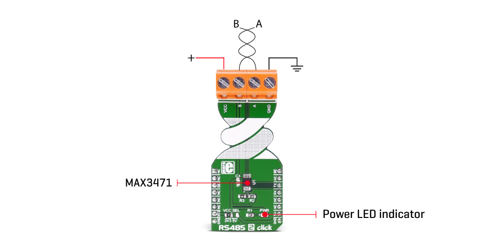
There are two pairs of screw terminals on board the RS485 2 Click. The ones marked with A and B are differential high and differential low communication lines. We added two more terminals for VCC and GND reference if needed for further interfacing.
 .
.
We provide a demo application for the RS485 2 Click Board™ on our LibStock page, as well as a demo application (example), developed using MikroElektronika compilers. The demo can run on all the main MikroElektronika development boards.
Library initializes and defines GPIO driver and performs control of device voltage.
For more details check the documentation.
void rs485_2_writeByte(uint8_t input) - Write Single Byte.uint8_t rs485_2_readByte() - Read Single Byte.uint8_t ras485_2_byteReady() - Check for new byte received.The application is composed of three sections:
void applicationTask()
{
 char tmp;
 uint8_t rdyFlag;

// RECEIVER - UART polling

 rdyFlag = rs485_2_byteReady();

 if (1 == rdyFlag)
 {
 tmp = rs485_2_readByte();
 mikrobus_logWrite( &tmp, _LOG_BYTE );
 }

// TRANSMITER - TX each 2 sec

 for (tmp = 0; tmp < 9; tmp++)
 {
 rs485_2_writeByte( MESSAGE_DATA[tmp] );
 mikrobus_logWrite( "MESSAGE SENT", _LOG_LINE );
 }
 Delay_ms(2000);
}
The full application code and ready to use projects can be found on our LibStock page.
Other mikroE Libraries used in this example:
Depending on the development board you are using, you may need USB UART click, USB UART 2 click or RS232 click to connect to your PC, for development systems with no UART to USB interface available on the board. The terminal available in all MikroElektronika compilers, or any other terminal application of your choice, can be used to read the message.
The RS485 2 Click Board™ is supported by mikroSDK - MikroElektronika Software Development Kit. To ensure proper operation of mikroSDK compliant click board demo applications, mikroSDK should be downloaded from the LibStock and installed for the compiler you are using.
- condition: new - custom_product: false - mpn: MIKROE-2700 - google_product_category: Electronics - custom_label_0: Click Board - attachments: [{"download_file":[{"download_file":"RS485 2 Click Board™ Schematic"}],"download_filetype":[{"download_filetype":"pdf"}]},{"download_file":[{"download_file":"Maxim MAX3471 Helf-Duplex Transceiver Datasheet"}],"download_filetype":[{"download_filetype":"pdf"}]}] - device_vendor: Maxim Integrated - device_type: MAX3471CUA+ - warranty: 12 months - brand: MikroE - manufacturer: Mikroelektronika d.o.o. - brands: gid://shopify/Metaobject/56256004319 - breadcrumbs: ["gid://shopify/Collection/447955239135","gid://shopify/Collection/241680580797","gid://shopify/Collection/241546100925"] - customhs_code: 847330 - detailed_description: {"type":"root","children":[{"type":"paragraph","children":[{"type":"text","value":"Due to its reliability and robustness, the "},{"type":"text","value":"RS485 2 Click Board™","bold":true},{"type":"text","value":" can be used in various applications that require reliable data transfer in various noisy environments, or over a substantial distance, when data rate transfer up to 64 kbps is sufficient. Featuring very low power consumption, it can also be used with the battery powered RS485/422 applications. The "},{"type":"text","value":"RS485 2 Click Board™","bold":true},{"type":"text","value":" can be used for controlling various building automation systems, battery-powered differential communicators, remote meter reading applications, and various other battery operated or portable devices, which need to establish a reliable communication over the RS422/485 bus."}]},{"type":"heading","level":3,"children":[{"type":"text","value":"How Does The RS485 2 Click Board™ Work?"}]},{"type":"paragraph","children":[{"type":"text","value":"The "},{"type":"text","value":"RS485 2 Click Board™","bold":true},{"type":"text","value":" uses the MAX3471, an RS-422/485, half-duplex, differential transceiver for battery-powered systems, from Maxim Integrated. This click is intended to be used as a physical layer device, often referred to as PHY, providing physical interfacing of the MCU TTL level UART lines with the RS422/485 bus. It is well suited for transmitting smaller blocks of data over long distances, using a shielded differential pair, for both TX and RX signals, allowing for half-duplex asynchronous communication. The MAX3471 transceiver consists of a separate driver and receiver sections, with Driver Enable and Receiver Enable pins (#RE and DE), used to enable appropriate sections. Driver section is used to drive the RS422/485 bus with the signal received on the UART RX line labeled as RO on the IC, while the receiver section returns data from the bus back to the MCU via the UART TX line, labeled as DI on the IC in the schematics."}]},{"type":"paragraph","children":[{"type":"text","value":"RS422/485 standard only specifies electrical characteristics of the transmitter and the receiver. It does not specify or recommend any communications protocol, only the physical layer. The top layer communication protocol of choice can be used, such as the MODBUS or similar protocols. Therefore the "},{"type":"text","value":"RS485 2 Click Board™","bold":true},{"type":"text","value":" offers UART RX and TX pins, routed to the appropriate mikroBUS™ TX and RX UART pins. These pins are used by the MCU to send data to the RS485 bus, in a form determined by the user protocol. Additional DE and RE pins are routed to the mikroBUS™ CS and PWM pin respectively. These pins are labeled on the Click board™ as DE and RE, the same as on the IC itself. Pull-up and pull-down are used to determine states on these pins when they are left floating."},{"type":"text","value":""},{"type":"text","value":""},{"type":"text","value":""}]},{"type":"paragraph","children":[{"type":"text","value":"MAX3471 IC allows data rates up to 64kbps. In general, the maximal transfer speed is determined by the bus length: longer bus lines will result in less transfer speed. The RS485/422 bus needs to be terminated with the resistor on both ends, which is equal to the characteristic impedance of the used cable, in order to prevent line reflections. However, the MAX3471 IC features a reduced slew rate on its driver outputs, resulting with slower speed, but with far more robust signal at the same time, which is immune to EMI and other types of interferences that appear on long lines or connection stubs (unterminated parts of the bus). This IC is also able to work on the unterminated bus, commonly used in low speed and low power systems."}]},{"type":"paragraph","children":[{"type":"text","value":"The RS-485 standard specifies that a compliant driver must be able to drive 32 unit loads (UL), where 1 unit load represents a load impedance of approximately 12 kΩ. Since the MAX3471 IC device is 1/8 UL, up to 256 such receivers can be supported by a single driver. In cases when the RS485/422 bus voltage is close to 2.5V, the device is able to drive up to 8 loads, which means that it can drive up to 64 receivers. As the bus voltage rises, more drivers can be added, so that for 5V the device can drive the number of devices specified by the standard."}]},{"type":"paragraph","children":[{"type":"text","value":"There are situations on the RS485/422 bus, which might lead to a differential voltage which can increase the current which runs through the driver output. This state is known as the bus contention, and it commonly appears during the initialization, bus fault conditions, or with multiple nodes, which have their drivers active at the same time. The MAX3471 IC provides driver output protection, which limits this current and prevents damage to the driver output stage."}]},{"type":"paragraph","children":[{"type":"text","value":"The MAX3471 receiver employs input filtering and input hysteresis to enhance noise immunity when differential signals have very slow rise and fall times. MAX3471 IC features a true fail-safe receiver input, which guarantees a logic HIGH receiver output in cases when the receiver inputs are open or shorted, or when they are connected to a terminated transmission line with all drivers disabled."}]},{"type":"paragraph","children":[{"type":"text","value":"There is one 4-pole screw terminal on board (VCC, RX, TX, GND) for connecting RS422/485 bus twisted pair cable, along with the GND and VCC. The jumper labeled as VCC SEL is used to set the operating voltage of the Click board™ to either 3.3V or 5V. GND and VCC rails can be used to provide the power supply for another node. Note that the VCC terminal is directly routed to either 3.3V or 5V rail of the mikroBUS™, depending on the VCC SEL jumper position."}]},{"type":"paragraph","children":[{"type":"text","value":"MikroElektronika provides a library that contains functions compatible with the MikroElektronika compilers, which can be used for working with the "},{"type":"text","value":"RS485 2 Click Board™","bold":true},{"type":"text","value":". The library also contains an example application, which demonstrates their use. This example application can be used as a reference for custom designs."}]},{"type":"heading","level":3,"children":[{"type":"text","value":"Specifications"}]},{"type":"paragraph","children":[{"type":"text","value":"Type\nRS485\nApplications\nBattery-Powered Differential Communications\nOn-board modules\nMAX3471 half-duplex transceiver\nKey Features\n1.6µA Supply Current with Receiver Enabled; intended for lithium battery-powered RS-485/RS-422 applications.\nInterface\nUART\nCompatibility\nmikroBUS\nClick board size\nL (57.15 x 25.4 mm)\nInput Voltage\n3.3V or 5V"}]},{"type":"heading","level":3,"children":[{"type":"text","value":"Pinout diagram"}]},{"type":"paragraph","children":[{"type":"text","value":"This table shows how the pinout on the "},{"type":"text","value":"RS485 2 Click Board™","bold":true},{"type":"text","value":" ","bold":true},{"type":"text","value":"corresponds to the pinout on the mikroBUS™ socket (the latter shown in the two middle columns)."}]},{"type":"paragraph","children":[{"type":"text","value":"Notes\nPin\nPin\nNotes\nNC\n1\nAN\nPWM\n16\nRE\nReceiver output enable, active low\nNC\n2\nRST\nINT\n15\nNC\nDriver output enable, active high\nDE\n3\nCS\nTX\n14\nRX\nUART data receive \nNC\n4\nSCK\nRX\n13\nTX\nUART data transmit\nNC\n5\nMISO\nSCL\n12\nNC\nNC\n6\nMOSI\nSDA\n11\nNC\nPower supply\n+3.3V\n7\n3.3V\n5V\n10\n+5V\nPower supply\nGround\nGND\n8\nGND\nGND\n9\nGND\nGround"}]},{"type":"heading","level":3,"children":[{"type":"text","value":"Jumpers and settings"}]},{"type":"paragraph","children":[{"type":"text","value":"Designator\nName\nDefault Position\nDefault Option\nDescription\nJP1\nVCC SEL\nLeft\n3V3\nPower Supply Voltage Selection 3V3/5V, left position 3V3, right position 5V"}]},{"type":"heading","level":3,"children":[{"type":"text","value":" "}]}]} - summary:The RS485 2 Click Board™ carries the MAX3471 half-duplex transceiver intended for lithium battery-powered RS-485/RS-422 applications.
The RS485 2 Click Board™ is designed to run on either a 3.3V or 5V power supply. It communicates with the target microcontroller over the UART interface with additional functionality provided by the following pins on the MikroBUS line: PWM, CS.