The ADAC Click Board™ is an 8-channel 12-bit ADC, DAC and GPIO. It carries the AD5593R configurable ADC/DAC, from Analog Devices. The click is designed to run on either 3.3V or 5V power supply. The ADAC Click Board™ communicates with the target microcontroller over I2C interface, with additional functionality provided by the RST pin on the mikroBUS™ line.
Every channel can be set individually as ADC, DAC, or GPIO. The 12-bit conversion values are readable through I2C.
For resetting the IC, use the Reset pin (RST).
The AD5593R has eight input/output (I/O) pins, which can be independently configured as digital-to-analog converter (DAC) outputs, analog-to-digital converter (ADC) inputs, digital outputs, or digital inputs. When an I/O pin is configured as an analog output, it is driven by a 12-bit DAC. The output range of the DAC is 0 V to VREF or 0 V to 2×V REF.
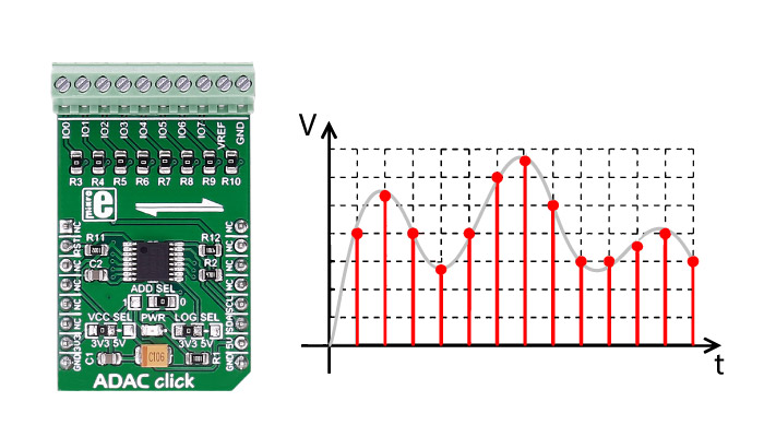
When an I/O pin is configured as an analog input, it is connected to a 12-bit ADC via an analog multiplexer. The input range of the ADC is 0 V to VREF or 0 V to 2 × VREF. The I/O pins can also be configured to be general-purpose, digital input or output (GPIO) pins.
| Type | ADC-DAC |
| Applications | control and monitoring, measurement, etc. |
| On-board modules | AD5593R 8-Channel, 12-Bit, Configurable ADC/DAC |
| Key Features | 8 12-bit DAC channels, 8 12-bit ADC channels |
| Interface | GPIO,I2C |
| Compatibility | mikroBUS |
| Click board size | M (42.9 x 25.4 mm) |
| Input Voltage | 3.3V or 5V |
This table shows how the pinout on the ADAC Click Board™ corresponds to the pinout on the mikroBUS™ socket (the latter shown in the two middle columns).
| Notes | Pin | Pin | Notes | ||||
|---|---|---|---|---|---|---|---|
| NC | 1 | AN | PWM | 16 | NC | ||
| Active low IC reset | RST | 2 | RST | INT | 15 | NC | |
| NC | 3 | CS | TX | 14 | NC | ||
| NC | 4 | SCK | RX | 13 | NC | ||
| NC | 5 | MISO | SCL | 12 | SCL | I2C serial clock | |
| NC | 6 | MOSI | SDA | 11 | SDA | I2C serial data | |
| Power supply | +3.3V | 7 | 3.3V | 5V | 10 | +5V | Power supply |
| Ground | GND | 8 | GND | GND | 9 | GND | Ground |
| Name | I/O | Description |
|---|---|---|
| IO0 | Multipurpouse IO pin(ADC,DAC,GPIO)channel0 | |
| IO1 | Multipurpouse IO pin(ADC,DAC,GPIO)channel1 | |
| IO2 | Multipurpouse IO pin(ADC,DAC,GPIO)channel2 | |
| IO3 | Multipurpouse IO pin(ADC,DAC,GPIO)channel3 | |
| IO4 | Multipurpouse IO pin(ADC,DAC,GPIO)channel4 | |
| IO5 | Multipurpouse IO pin(ADC,DAC,GPIO)channel5 | |
| IO6 | Multipurpouse IO pin(ADC,DAC,GPIO)channel6 | |
| IO7 | Multipurpouse IO pin(ADC,DAC,GPIO)channel7 | |
| VREF | OPTIONAL | Used as input for connecting external VREF or output 2.5V from internal |
| GND | OPTIONAL | Used for external connection to GND if VREF input is used |
| Designator | Name | Default Position | Default Option | Description |
|---|---|---|---|---|
| ADD SEL | Address bit | 0 | 3V3 | I2C slave address selection, set LSB of slave address 0010001x left pos, 0010000x right pos, (x=R/W) |
| VCC SEL | Power supply | 3V3 | Supply Voltage Selection 3V3/5V, left position 3v3, right position 5v | |
| LOG SEL | Interface power supply | 3V3 | Logic Level Voltage Selection 3V3/5V, left position 3v3, right position 5v |
The ADAC Click Board™ is an 8-channel 12-bit ADC, DAC and GPIO. It carries the AD5593R configurable ADC/DAC. The Click is designed to run on either 3.3V or 5V power supply. ADAC Click communicates with the target microcontroller over I2C interface, with additional functionality provided by the RST pin on the mikroBUS line.
Every channel can be set individually as ADC, DAC, or GPIO. The 12-bit conversion values are readable through I2C.
 .
.
For resetting the IC, use the Reset pin (RST).
The AD5593R has eight input/output (I/O) pins, which can be independently configured as digital-to-analog converter (DAC) outputs, analog-to-digital converter (ADC) inputs, digital outputs, or digital inputs. When an I/O pin is configured as an analog output, it is driven by a 12-bit DAC. The output range of the DAC is 0 V to VREF or 0 V to 2V REF.
When an I/O pin is configured as an analog input, it is connected to a 12-bit ADC via an analog multiplexer. The input range of the ADC is 0 V to VREF or 0 V to 2 . The I/O pins can also be configured to be general-purpose, digital input or output (GPIO) pins.
- amazon_main_image: https://www.thedebugstore.com/images/product/lg-adac-click-board.jpg - amazon_browse_node: 428655031 - related_products: MIKROE-950,MIKROE-1918,MIKROE-2038 - mpn: MIKROE-2690 - backorder_label: If no stock shown above, check availability - google_product_category: 259 - examples:Code examples for the ADAC Click Board™, written for MikroElektronika hardware and compilers are available on Libstock.
The following code snippet demonstrates the use of the ADAC Click Board™ library functions. It will first set a pin as an analog output, showing DAC function, and will then set a different pin as an analog input, showing ADC operation.
01 UART1_Write_Text ("rnrnStarting DAC Operation...");
02         Delay_ms (1000);
03         //Sets the IO3 pin as DAC
04         ADAC_setConfiguration (_ADAC_DAC_CONFIG, _ADAC_NULL, _ADAC_IO3);
05         //Rises the DAC output on IO3 from 0 to VREF
06         for (i = 0; i < 0xFFF; i+=4)
07         {
08             ADAC_writeDAC (_ADAC_DAC_WRITE | _ADAC_PB_PIN3, i/0x100, i%0x100);
09             Delay_ms (10);
10         }
11         UART1_Write_Text ("rnDAC Operation finishedrn");
12         Delay_ms (1000);
13
14
15        UART1_Write_Text ("rnStarting ADC Operation...");
16         Delay_ms (1000);
17         //Sets the IO4 pin as ADC
18         ADAC_setConfiguration (_ADAC_ADC_CONFIG, _ADAC_NULL, _ADAC_IO4);
19         //Sets the ADC sequence repetition to enabled, and adds IO4 to sequence
20         ADAC_setConfiguration (_ADAC_ADC_SEQUENCE, _ADAC_SEQUENCE_ON, _ADAC_IO4);
21         //Reads the ADC input, and writes it to UART1
22         for (i = 0; i < 8; i++)
23         {
24             ADCValue = ADAC_readADC ( _ADAC_ADC_READ, &channel );
25             ShortToStr (channel, uartText);
26             UART1_Write_Text ("rnRead value from channel");
27             UART1_Write_Text (uartText);
28
29
30            IntToStr (ADCValue, uartText);
31             UART1_Write_Text (": ");
32             UART1_Write_Text (uartText);
33             Delay_ms (2000);
34         }
35
36        UART1_Write_Text ("rnADC Operation finished");
37         Delay_ms (1000);
- attachments: [{"download_file":[{"download_file":"ADAC Click Board™ Schematic"}],"download_filetype":[{"download_filetype":"pdf"}]},{"download_file":[{"download_file":"Analog Devices AD5593R 8-ch, 12-bit ADC/DAC Datasheet"}],"download_filetype":[{"download_filetype":"pdf"}]}]
- condition: new
- custom_product: false
- mpn: MIKROE-2690
- google_product_category: Electronics
- custom_label_0: Click Board
- device_vendor: Analog Devices Inc.
- device_type: AD5593RBRUZ
- warranty: 12 months
- brand: MikroE
- manufacturer: Mikroelektronika d.o.o.
- badge:
- widget: The ADAC Click Board™ is an 8-channel 12-bit ADC, DAC and GPIO. ADAC Click Board™ communicates with the target microcontroller over the I2C interface, with additional functionality provided by the RST pin on the MikroBUS line.
The ADAC Click Board™ is designed to run on either a 3.3V or 5V power supply.