# Title: Flicker Click Board™
## Description: FLICKER Click Board™ Thanks to the onboard NE556DR dual precision timer from Texas Instruments and the G6D-ASI power PCB relay from Omron, the FLICKER Click Board™ can control loads up to 5A, 250 VAC/30 VDC at a predefined time interval. The on/off period can last from 0.1 to 6 seconds, that can be set by the two ON/OFF onboard potentiometers. The external load can be connected to the board through the screw terminal. The FLICKER Click Board™ runs on 5V power supply and it communicates with the MCU over RST pin. DO NOT TOUCH THE BOARD WHILE THE EXTERNAL POWER SUPPLY IS ON! Note: The FLICKER Click Board™ has exposed pins/pads. To stay safe take precaution when applying high voltage to the click. The click is to be used by trained personnel only when applying high voltage. Applications The FLICKER Click Board™ is the perfect, simple solution if you need to turn a device on and off at specific time intervals, like blinking LED commercials, alarm system lights, or any other signaling lights. SPECIFICATIONS Type Relay Applications The FLICKER Click Board™ is the perfect, simple solution if you need to turn a device on and off at specific time intervals, like blinking LED commercials, alarm system lights, or any other signalling lights On-board modules NA556 dual precision timer from Texas Instruments and the G6D-ASI power PCB relay from Omron Key Features G6D-ASI power PCB relay, Max. loads up to 5 A, 250 VAC/30 VDC, Min. permissible load 10 mA at 5 VDC, Contact resistance 100 mΩ max Interface GPIO Compatibility mikroBUS Click board size L (57.15 x 25.4 mm) Input Voltage 5V PINOUT DIAGRAM This table shows how the pinout of the FLICKER Click Board™ corresponds to the pinout on the mikroBUS™ socket (the latter shown in the two middle columns). Notes Pin Pin Notes NC 1 AN PWM 16 NC Turns the NE556 on and off FON 2 RST INT 15 NC NC 3 CS RX 14 NC NC 4 SCK TX 13 NC NC 5 MISO SCL 12 NC NC 6 MOSI SDA 11 NC NC 7 +3.3V +5V 10 +5V +5V power supply Ground GND 8 GND GND 9 GND ONBOARD PCB RELAY Maximum switching capacity of the G6D-ASI PCB relay is 1250VA at 150W. Maximum contact resistance is 100 mΩ. POTENTIOMETERS The two potentiometers (P1 and P2) set the switching on and off time. Designator Name Type Description P1 Potentiometer Adjusting Ton P2 Potentiometer Adjusting Toff CN1 Terminal block Connector for connecting the device MAXIMUM RATINGS Description Min Typ Max Unit Contact resistance 100m Ω Operate time 10m s Ambient temperature -25 70 C Operating current 5 A Operating voltage 250 VAC
## Product type: Click Board
## Vendor: Mikroelektronika d.o.o.
## Tags: Click Board, MikroE, Misc, Omron, Relay
## Price range: 16.1 - 16.1 GBP
## Link: https://thedebugstore.com/products/mikroe-2481-flicker-click-board-uk
## Compare-at price range: 23.0 - 23.0 GBP
## Options
- Title: Default Title
## Collections
- [New Products](https://thedebugstore.com/a/llms/collections/new-products-debug-store)
- [Mikroelektronika d.o.o. (MikroE)](https://thedebugstore.com/a/llms/collections/mikroelektronika-catalogue-uk)
- [Omron Device Support: Development Boards and Tools for Industrial Automation](https://thedebugstore.com/a/llms/collections/omrom-device-support-uk)
- [Miscellaneous Click Boards™](https://thedebugstore.com/a/llms/collections/miscellaneous-click-boards-catalogue)
- [MikroE Click Boards™](https://thedebugstore.com/a/llms/collections/mikroe-click-boards-catalogue-uk)
- [Relay Click Boards™](https://thedebugstore.com/a/llms/collections/relay-click-boards-catalogue)
- [Click Boards™ Summer Sale](https://thedebugstore.com/a/llms/collections/inventory-sale)
- [MikroE Sale](https://thedebugstore.com/a/llms/collections/mikroe-sale)
- [MIKROE Stock](https://thedebugstore.com/a/llms/collections/mikroe-products-in-stock-sale)
## Variants
- Default Title, SKU: MIKROE-2481, Available: yes, Inventory: 1
## Metafields
- full_description: FLICKER Click Board™
Thanks to the onboard NE556DR dual precision timer from Texas Instruments and the G6D-ASI power PCB relay from Omron, the FLICKER Click Board™ can control loads up to 5A, 250 VAC/30 VDC at a predefined time interval.
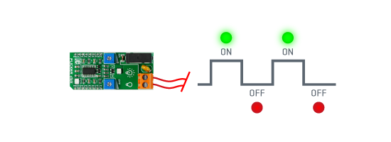
The on/off period can last from 0.1 to 6 seconds, that can be set by the two ON/OFF onboard potentiometers. The external load can be connected to the board through the screw terminal. The FLICKER Click Board™ runs on 5V power supply and it communicates with the MCU over RST pin.
 DO NOT TOUCH THE BOARD WHILE THE EXTERNAL POWER SUPPLY IS ON!
Note: The FLICKER Click Board™ has exposed pins/pads. To stay safe take precaution when applying high voltage to the click. The click is to be used by trained personnel only when applying high voltage.
Applications
The FLICKER Click Board™ is the perfect, simple solution if you need to turn a device on and off at specific time intervals, like blinking LED commercials, alarm system lights, or any other signaling lights.
SPECIFICATIONS
| Type |
Relay |
| Applications |
The FLICKER Click Board™ is the perfect, simple solution if you need to turn a device on and off at specific time intervals, like blinking LED commercials, alarm system lights, or any other signalling lights |
| On-board modules |
NA556 dual precision timer from Texas Instruments and the G6D-ASI power PCB relay from Omron |
| Key Features |
G6D-ASI power PCB relay, Max. loads up to 5 A, 250 VAC/30 VDC, Min. permissible load 10 mA at 5 VDC, Contact resistance 100 mΩ max |
| Interface |
GPIO |
| Compatibility |
mikroBUS |
| Click board size |
L (57.15 x 25.4 mm) |
| Input Voltage |
5V |
PINOUT DIAGRAM
This table shows how the pinout of the FLICKER Click Board™ corresponds to the pinout on the mikroBUS™ socket (the latter shown in the two middle columns).
| Notes |
Pin |
 |
Pin |
Notes |
| NC |
1 |
AN |
PWM |
16 |
NC |
| Turns the NE556 on and off |
FON |
2 |
RST |
INT |
15 |
NC |
| NC |
3 |
CS |
RX |
14 |
NC |
| NC |
4 |
SCK |
TX |
13 |
NC |
| NC |
5 |
MISO |
SCL |
12 |
NC |
| NC |
6 |
MOSI |
SDA |
11 |
NC |
| NC |
7 |
+3.3V |
+5V |
10 |
+5V |
+5V power supply |
| Ground |
GND |
8 |
GND |
GND |
9 |
GND |
ONBOARD PCB RELAY
Maximum switching capacity of the G6D-ASI PCB relay is 1250VA at 150W. Maximum contact resistance is 100 mΩ.
POTENTIOMETERS
The two potentiometers (P1 and P2) set the switching on and off time.
| Designator |
Name |
Type |
Description |
| P1 |
Potentiometer |
Adjusting Ton |
| P2 |
Potentiometer |
Adjusting Toff |
| CN1 |
Terminal block |
Connector |
for connecting the device |
MAXIMUM RATINGS
| Description |
Min |
Typ |
Max |
Unit |
| Contact resistance |
100m |
Ω |
| Operate time |
10m |
s |
| Ambient temperature |
-25 |
70 |
C |
| Operating current |
5 |
A |
| Operating voltage |
250 |
VAC |
- description_tag: Thanks to the onboard NA556 dual precision timer from Texas Instruments and the G6D-ASI power PCB relay from Omron, the FLICKER Click Board™ can control loads up to 5A, 250 VAC/30 VDC at a predefined time interval. Available from Debug Store UK.
- title_tag: MikroE Flicker Click Board™ (MIKROE-2481)
- manufacturer: Mikroelektronika d.o.o.
- warranty: 12 months
- amazon_enable: TRUE
- amazon_title: Flicker Click Board
- amazon_product_type: computercomponent
- amazon_block: FALSE
- amazon_prime_enable: FALSE
- amazon_search: MikroElektronika Microelectronica MIKROE-1100
- amazon_uk_price: 16.72
- amazon_uk_currency: GBP
- amazon_de_currency: EUR
- amazon_de_price: 18.8936
- amazon_fr_currency: EUR
- amazon_fr_price: 18.8936
- amazon_es_currency: EUR
- amazon_es_price: 18.8936
- amazon_nl_currency: EUR
- amazon_nl_price: 18.8936
- amazon_it_currency: EUR
- amazon_it_price: 18.8936
- amazon_se_curency: SEK
- amazon_se_price: 190.608
- amazon_product_id: 8606015079356
- amazon_product_id_type: EAN
- amazon_update: Update
- amazon_short_description: Thanks to the on-board NA556 dual precision timer from Texas Instruments and the G6D-ASI power PCB relay from Omron, the FLICKER Click Board™ can control loads up to 5A, 250 VAC/30 VDC at a predefined time interval.The on/off period can last from 0.1 to 6 seconds, that can be set by the two ON/OFF on-board potentiometers. The external load can be connected to the board through the screw terminal. FLICKER Click Board™ runs on 5V power supply and it communicates with the MCU over RST pin.
- amazon_long_description: Thanks to the on-board NA556 dual precision timer from Texas Instruments and the G6D-ASI power PCB relay from Omron, the FLICKER Click Board™ can control loads up to 5A, 250 VAC/30 VDC at a predefined time interval.
The on/off period can last from 0.1 to 6 seconds, that can be set by the two ON/OFF on-board potentiometers. The external load can be connected to the board through the screw terminal. FLICKER Click Board™ runs on 5V power supply and it communicates with the MCU over RST pin.
- amazon_main_image: https://www.thedebugstore.com/images/product/lg-flicker-click-board.jpg
- amazon_browse_node: 428655031
- mpn: MIKROE-2481
- backorder_label: If no stock shown above, check availability
- badge: No reviews
- widget:
- condition: new
- custom_product: false
- mpn: MIKROE-2481
- google_product_category: Electronics
- custom_label_0: Click Board
- examples:
This code snippet configures required port E as digital, sets pins 1 and 2 as input and enters an infinite loop. While in an infinite loop, use potentiometers P1 and P2 to adjust the ON / OFF time period.
- Supply voltage within range of 5 – 15 V.
- Maximum output current detected : 225 mA.
- Usable on : ARM, PIC, PIC32, AVR and FTDI compilers.
 1
 2    void main()
 3     {
 4       ANSELE = 0;            // Configure PORTE pins as digital
 5       TRISE2_bit = 1;        // Set RE2 pin as input
 6       PORTE = 0;
 7       while(1);              // Endless loop
 8                              // While Button is held, the onboard LED will blink according to ON/OFF timer
 9                              // For example, connect beeper from digital multimeter on terminal
10     }
- attachments: [{"download_file":[{"download_file":"Flicker Click Board™ Schematic"}],"download_filetype":[{"download_filetype":"pdf"}]},{"download_file":[{"download_file":"Texas Instruments NA556 Dual Precision Timer Datasheet"}],"download_filetype":[{"download_filetype":"pdf"}]},{"download_file":[{"download_file":"Omron G6D Relay Datasheet"}],"download_filetype":[{"download_filetype":"pdf"}]}]
- device_vendor: Omron Electronics Inc-EMC Div, Texas Instruments
- device_type: G6D-1A-ASI DC5, NE556DR
- warranty: 12 months
- brand: MikroE
- manufacturer: Mikroelektronika d.o.o.
- brands: gid://shopify/Metaobject/56256004319
- breadcrumbs: ["gid://shopify/Collection/447955239135","gid://shopify/Collection/241680580797","gid://shopify/Collection/241546559677"]
- customhs_code: 847330
- detailed_description: {"type":"root","children":[{"type":"heading","level":3,"children":[{"type":"text","value":"FLICKER Click Board™"}]},{"type":"paragraph","children":[{"type":"text","value":"Thanks to the onboard NE556DR dual precision timer from Texas Instruments and the G6D-ASI power PCB relay from Omron, the "},{"type":"text","value":"FLICKER Click Board™","bold":true},{"type":"text","value":" can control loads up to 5A, 250 VAC/30 VDC at a predefined time interval."}]},{"type":"paragraph","children":[{"type":"text","value":"The on/off period can last from 0.1 to 6 seconds, that can be set by the two ON/OFF onboard potentiometers. The external load can be connected to the board through the screw terminal. The "},{"type":"text","value":"FLICKER Click Board™","bold":true},{"type":"text","value":" runs on 5V power supply and it communicates with the MCU over RST pin."}]},{"type":"paragraph","children":[{"type":"text","value":""}]},{"type":"paragraph","children":[{"type":"text","value":""},{"type":"text","value":"DO NOT TOUCH THE BOARD WHILE THE EXTERNAL POWER SUPPLY IS ON!"}]},{"type":"paragraph","children":[{"type":"text","value":"Note","bold":true},{"type":"text","value":": The "},{"type":"text","value":"FLICKER Click Board™","bold":true},{"type":"text","value":" has exposed pins/pads. To stay safe take precaution when applying high voltage to the click. The click is to be used by trained personnel only when applying high voltage."}]},{"type":"heading","level":3,"children":[{"type":"text","value":""},{"type":"text","value":"Applications"}]},{"type":"paragraph","children":[{"type":"text","value":"The "},{"type":"text","value":"FLICKER Click Board™ ","bold":true},{"type":"text","value":"is the perfect, simple solution if you need to turn a device on and off at specific time intervals, like blinking LED commercials, alarm system lights, or any other signaling lights."}]},{"type":"heading","level":3,"children":[{"type":"text","value":"SPECIFICATIONS"}]},{"type":"paragraph","children":[{"type":"text","value":"Type\nRelay\nApplications\nThe FLICKER Click Board™ is the perfect, simple solution if you need to turn a device on and off at specific time intervals, like blinking LED commercials, alarm system lights, or any other signalling lights\nOn-board modules\nNA556 dual precision timer from Texas Instruments and the G6D-ASI power PCB relay from Omron\nKey Features\nG6D-ASI power PCB relay, Max. loads up to 5 A, 250 VAC/30 VDC, Min. permissible load 10 mA at 5 VDC, Contact resistance 100 mΩ max\nInterface\nGPIO\nCompatibility\nmikroBUS\nClick board size\nL (57.15 x 25.4 mm)\nInput Voltage\n5V"}]},{"type":"heading","level":3,"children":[{"type":"text","value":"PINOUT DIAGRAM"}]},{"type":"paragraph","children":[{"type":"text","value":"This table shows how the pinout of the "},{"type":"text","value":"FLICKER Click Board™","bold":true},{"type":"text","value":" corresponds to the pinout on the mikroBUS™ socket (the latter shown in the two middle columns)."}]},{"type":"paragraph","children":[{"type":"text","value":"Notes\nPin\nPin\nNotes\nNC\n1\nAN\nPWM\n16\nNC\nTurns the NE556 on and off\nFON\n2\nRST\nINT\n15\nNC\nNC\n3\nCS\nRX\n14\nNC\nNC\n4\nSCK\nTX\n13\nNC\nNC\n5\nMISO\nSCL\n12\nNC\nNC\n6\nMOSI\nSDA\n11\nNC\nNC\n7\n+3.3V\n+5V\n10\n+5V\n+5V power supply\nGround\nGND\n8\nGND\nGND\n9\nGND"}]},{"type":"heading","level":3,"children":[{"type":"text","value":"ONBOARD PCB RELAY"}]},{"type":"paragraph","children":[{"type":"text","value":"Maximum switching capacity of the G6D-ASI PCB relay is 1250VA at 150W. Maximum contact resistance is 100 mΩ."}]},{"type":"heading","level":3,"children":[{"type":"text","value":"POTENTIOMETERS"}]},{"type":"paragraph","children":[{"type":"text","value":"The two potentiometers (P1 and P2) set the switching on and off time."}]},{"type":"paragraph","children":[{"type":"text","value":"Designator\nName\nType\nDescription\nP1\nPotentiometer\nAdjusting Ton\nP2\nPotentiometer\nAdjusting Toff\nCN1\nTerminal block\nConnector\nfor connecting the device"}]},{"type":"heading","level":3,"children":[{"type":"text","value":"MAXIMUM RATINGS"}]},{"type":"paragraph","children":[{"type":"text","value":"Description\nMin\nTyp\nMax\nUnit\nContact resistance\n100m\nΩ\nOperate time\n10m\ns\nAmbient temperature\n-25\n70\nC\nOperating current\n5\nA\nOperating voltage\n250\nVAC"}]},{"type":"heading","level":3,"children":[{"type":"text","value":" "}]}]}
- summary: Thanks to the onboard NA556 dual precision timer from Texas Instruments and the G6D-ASI power PCB relay from Omron, the FLICKER Click Board™ can control loads up to 5A, 250 VAC/30 VDC at a predefined time interval.
The on/off period can last from 0.1 to 6 seconds, which can be set by the two ON/OFF onboard potentiometers. The external load can be connected to the board through the screw terminal. FLICKER Click Board™ runs on a 5V power supply and it communicates with the MCU over the RST pin.