The EEPROM 3 Click Board™ provides 2 Mbit (2,097,152 bits) of Electrically Erasable Programmable Read Only Memory, organized in bytes. In other words, this click board™ is an EEPROM memory medium with the capacity of 256 KB. The used EEPROM module has outstanding endurance, with 1,000,000 write cycles and data retention period of over 100 years. The EEPROM module on this click features Schmitt trigger inputs for better noise protection, self-timed write cycles, it has a dedicated write protect pin for hardware protection of stored data, and error detection and correction logic scheme that ensures reliable data output, staying transparent to the host controller.
The EEPROM 3 Click Board™ is aimed towards industrial and commercial applications, which require low voltage and low power operational capabilities. It can be used for any kind of temporary or permanent data storage for various embedded electronic devices, simple data logging, storing various working parameters of a module or device, safeguarding the sensitive data in case of a power cycle, and other similar applications where reliable EEPROM memory is needed.
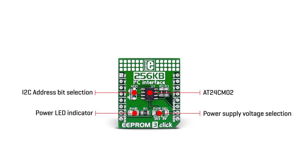
The EEPROM module used on the EEPROM 3 Click Board™ is the AT24CM02, an I2C serial EEPROM from Microchip, with the memory cell density of 2 megabits (Mbit). The EEPROM density is usually expressed in bits, so exactly 2,097,152 bits are organized in units or words of 8 bits, which gives 262,144 bytes of data memory. Furthermore, the EEPROM is organized in so-called pages. One page holds 256 bytes and there are 1024 pages (1024 pages x 256 bytes = 262,144 bytes total). Having insight into how the memory cells are organized, is important for Write and Erase operations. The I2C pins are routed to the mikroBUS™ so the communication is easy and straightforward. Both 100KHz and 400KHz transfer speeds are supported by the AT24CM02 IC, as well as the 1MHz Fast Mode Plus (FM+) I2C communication, for the MCUs with I2C modules that can support that speed.
The EEPROM 3 Click Board™ uses the I2C communication protocol. Therefore, every data transaction event is initiated by the host MCU, transmitting the I2C START condition, followed by the AT24CM02 device ID byte. Upon the receiving of the device ID byte, the AT24CM02 IC expects two more address bytes, completing the 18bit address word.
The AT24CM02 IC supports Byte write instruction, which allows one single byte to be written during the write cycle. After successful write cycle, the AT24CM02 IC sends an I2C Acknowledge signal (ACK) and the master then terminates the I2C communication with the I2C STOP condition.
When using a Page write instruction, 256 bytes will be written during one write cycle. It is possible to write less than 256 bytes, but if there is still incoming data when the end of the page is reached, the write pointer will roll over to the beginning of the same page, overwriting the content there. The special care should be taken to the page alignment.
Data Read is initiated the same way as the Data Write, except that the R/W bit is set to 1. There are several read modes available, including current address read, random address read and sequential address read. These modes are selected by the host MCU action. For example, a sequential read is performed by the ACK condition sent from the MCU after the successful byte read. If the host MCU responds with the NACK condition, the sequence reading will be terminated, the address pointer will not be incremented any further, and the communication can then be terminated with the I2C STOP condition.
Whenever I2C communication is suspended, after receiving the I2C STOP signal, or after receiving the NACK signal, the device reverts to the Standby mode, which minimizes the power consumption of the AT24CM02 IC, making it a good choice for applications that require low power consumption.
One of the key features of the AT24CM02 IC is the Error Detection and Correction scheme (EDC), which allows error correction by utilizing six additional bits, internally assigned to a group of four bytes. This protection scheme is capable of correcting some types of bit errors, staying transparent to the end user. The bit comparison and error correction are done internally.
The EEPROM 3 Click Board™ offers a selection between 3.3V and 5V operation, with the onboard SMD jumper, labeled as PWR SEL. This allows both 3.3V and 5V MCUs to be interfaced with this Click board™.
The attached device datasheet contains an in-depth explanation of all the mentioned functions. However, MikroElektronika provides a library with functions that make the final code clean and readable, simplifying working with this device. These functions internally employ the aforementioned communication mechanism and expose only a simple and clean interface to the user. The provided example code demonstrates the functionality of these functions. It can be used as a reference point for a custom development.
| Type | EEPROM |
| Applications | The EEPROM 3 Click Board™ is an excellent choice for storing initialization and configuration data of your device, when an I2C interface is required |
| On-board modules | Atmel's AT24CM02 DIP-8 socket EEPROM chip |
| Key Features | 256 KB of memory. I2C interface |
| Interface | I2C |
| Compatibility | mikroBUS |
| Click board size | S (28.6 x 25.4 mm) |
| Input Voltage | 3.3V or 5V |
This table shows how the pinout on the EEPROM 3 Click Board™ corresponds to the pinout on the mikroBUS™ socket (the latter shown in the two middle columns).
| Notes | Pin | Pin | Notes | ||||
|---|---|---|---|---|---|---|---|
| NC | 1 | AN | PWM | 16 | NC | ||
| NC | 2 | RST | INT | 15 | NC | ||
| NC | 3 | CS | RX | 14 | NC | ||
| NC | 4 | SCK | TX | 13 | NC | ||
| NC | 5 | MISO | SCL | 12 | SCL | I2C Clock | |
| NC | 6 | MOSI | SDA | 11 | SDA | I2C Data | |
| Power Supply | +3V3 | 7 | 3.3V | 5V | 10 | +5V | Power Supply |
| Ground | GND | 8 | GND | GND | 9 | GND | Ground |
| Label | Name | Default | Description |
|---|---|---|---|
| PWR | PWR | - | Power LED Indicator |
| PWR SEL | PWR SEL | Left | Logic voltage level selection: left position 3V3, right position 5V |
| ADD | ADD | Up | I2C address bit selection: up position 1, down position 0 |
The AT24CM02 module by Atmel provides 262,144 x 8 bits of serial EEPROM. The cascadable feature facilitates up to two devices to share a common 2-wire bus. This I2C-compatible AT24CM02 has byte and page Write speeds equal or less than 10 ms. It is well-suited for use in many industrial and commercial applications.
The I2C interface operates at 100 kHz in standard mode (1.7V to 5.5V), 400 kHz in fast mode (1.7 to 5.5V) and 1 MHz in fast mode plus (FM+), 2.5V to 5.5V.
EEPROM 3 Click features on-board zero-ohm SMD jumper that enables the user to select between a power supply source (3.3V or 5V). Another jumper, ADD, allows for selecting the I2C address.
The I2C interface compatible EEPROM 3 Click (1 MHz in fastest mode) is not as fast as the SPI-compatible EEPROM 2 Click (5 MHz speed). But it has the benefit of selectable addresses. On soldering the ADD jumpers in opposite positions, the user can use both simultaneously on the same I2C bus line, giving a total of 512 KB of memory.
- amazon_main_image: https://www.thedebugstore.com/images/product/lg-eeprom-3-front_1_1_1.jpg - amazon_other_image_1: https://www.thedebugstore.com/images/product/lg-eeprom-3-back_1.jpg - amazon_other_image_2: https://www.thedebugstore.com/images/product/lg-eeprom-3-click-in-use_1.jpg - amazon_other_image_3: https://www.thedebugstore.com/images/product/lg-eeprom-3-click-in-use_1.jpg - amazon_browse_node: 428655031 - mpn: MIKROE-1989 - backorder_label: If no stock shown above, check availability - badge: - widget:We provide a library for the EEPROM 3 Click Board™ on our Libstock page, as well as a demo application (example), developed using MikroElektronika compilers and mikroSDK. The provided click library is mikroSDK standard compliant. The demo application can run on all the main MikroElektronika development boards.
This library provides generic functions enough to have complete control over the EEPROM 3 Click Board™.
void eeprom3_writePage( uint16_t address, uint8_t *_data, uint8_t count ); - Writes data to the EEPROM ( maximum 256 Bytes ).void eeprom3_read( uint16_t address, uint8_t *buffer, uint16_t count ); - Reads data from EEPROM.The application is composed of three sections:
void applicationTask()
{

 eeprom3_writePage(0x0423, &text[0], 6);
 mikrobus_logWrite("Writing Mikroe to EEPROM 3 click", _LOG_LINE);
 Delay_ms(1000);
 eeprom3_read(0x0423,&memValue[0],6);
 mikrobus_logWrite("Data read:", _LOG_LINE);
 mikrobus_logWrite(memValue, _LOG_LINE);
 Delay_ms(1000);

}
The full application code, and ready to use projects can be found on our Libstock page.
Other mikroE Libraries used in the example:
Depending on the development board you are using, you may need USB UART click, USB UART 2 click or RS232 click to connect to your PC, for development systems with no UART to USB interface available on the board. The terminal available in all MikroElektronika compilers, or any other terminal application of your choice, can be used to read the message.
The EEPROM 3 Click Board™ is supported by mikroSDK - MikroElektronika Software Development Kit. To ensure proper operation of mikroSDK compliant click board demo applications, mikroSDK should be downloaded from the LibStock and installed for the compiler you are using.
- attachments: [{"download_file":[{"download_file":"EEPROM 3 Click Board™ Schematic"}],"download_filetype":[{"download_filetype":"pdf"}]},{"download_file":[{"download_file":"Microchip AT24CM02 2Mb I2C Serial EEPROM Datasheet"}],"download_filetype":[{"download_filetype":"pdf"}]}] - condition: new - custom_product: false - mpn: MIKROE-1989 - google_product_category: Electronics - custom_label_0: Click Board - device_vendor: Atmel - device_type: AT24CM02-SSHD-T - warranty: 12 months - brand: MikroE - key_feature_1: Based on a 2Mbit EEPROM - manufacturer: Mikroelektronika d.o.o. - brands: gid://shopify/Metaobject/56256004319 - breadcrumbs: ["gid://shopify/Collection/447955239135","gid://shopify/Collection/241680580797","gid://shopify/Collection/241545183421"] - customhs_code: 847330 - detailed_description: {"type":"root","children":[{"type":"paragraph","children":[{"type":"text","value":""}]},{"type":"paragraph","children":[{"type":"text","value":"The"},{"type":"text","value":" EEPROM 3 Click Board™","bold":true,"italic":true},{"type":"text","value":" ","bold":true},{"type":"text","value":" provides 2 Mbit (2,097,152 bits) of Electrically Erasable Programmable Read Only Memory, organized in bytes. In other words, this click board™ is an EEPROM memory medium with the capacity of 256 KB. The used EEPROM module has outstanding endurance, with 1,000,000 write cycles and data retention period of over 100 years. The EEPROM module on this click features Schmitt trigger inputs for better noise protection, self-timed write cycles, it has a dedicated write protect pin for hardware protection of stored data, and error detection and correction logic scheme that ensures reliable data output, staying transparent to the host controller."}]},{"type":"paragraph","children":[{"type":"text","value":"The "},{"type":"text","value":"EEPROM 3 Click Board™","bold":true},{"type":"text","value":" is aimed towards industrial and commercial applications, which require low voltage and low power operational capabilities. It can be used for any kind of temporary or permanent data storage for various embedded electronic devices, simple data logging, storing various working parameters of a module or device, safeguarding the sensitive data in case of a power cycle, and other similar applications where reliable EEPROM memory is needed."}]},{"type":"heading","level":3,"children":[{"type":"text","value":"How Does The EEPROM 3 Click Board™ Work?"}]},{"type":"paragraph","children":[{"type":"text","value":"The EEPROM module used on the "},{"type":"text","value":"EEPROM 3 Click Board™","bold":true},{"type":"text","value":" is the AT24CM02, an I2C serial EEPROM from Microchip, with the memory cell density of 2 megabits (Mbit). The EEPROM density is usually expressed in bits, so exactly 2,097,152 bits are organized in units or words of 8 bits, which gives 262,144 bytes of data memory. Furthermore, the EEPROM is organized in so-called pages. One page holds 256 bytes and there are 1024 pages (1024 pages x 256 bytes = 262,144 bytes total). Having insight into how the memory cells are organized, is important for Write and Erase operations. The I2C pins are routed to the mikroBUS™ so the communication is easy and straightforward. Both 100KHz and 400KHz transfer speeds are supported by the AT24CM02 IC, as well as the 1MHz Fast Mode Plus (FM+) I2C communication, for the MCUs with I2C modules that can support that speed."},{"type":"text","value":""},{"type":"text","value":""},{"type":"text","value":""}]},{"type":"paragraph","children":[{"type":"text","value":"The "},{"type":"text","value":"EEPROM 3 Click Board™","bold":true},{"type":"text","value":" uses the I2C communication protocol. Therefore, every data transaction event is initiated by the host MCU, transmitting the I2C START condition, followed by the AT24CM02 device ID byte. Upon the receiving of the device ID byte, the AT24CM02 IC expects two more address bytes, completing the 18bit address word."}]},{"type":"paragraph","children":[{"type":"text","value":"The AT24CM02 IC supports Byte write instruction, which allows one single byte to be written during the write cycle. After successful write cycle, the AT24CM02 IC sends an I2C Acknowledge signal (ACK) and the master then terminates the I2C communication with the I2C STOP condition."}]},{"type":"paragraph","children":[{"type":"text","value":"When using a Page write instruction, 256 bytes will be written during one write cycle. It is possible to write less than 256 bytes, but if there is still incoming data when the end of the page is reached, the write pointer will roll over to the beginning of the same page, overwriting the content there. The special care should be taken to the page alignment."}]},{"type":"paragraph","children":[{"type":"text","value":"Data Read is initiated the same way as the Data Write, except that the R/W bit is set to 1. There are several read modes available, including current address read, random address read and sequential address read. These modes are selected by the host MCU action. For example, a sequential read is performed by the ACK condition sent from the MCU after the successful byte read. If the host MCU responds with the NACK condition, the sequence reading will be terminated, the address pointer will not be incremented any further, and the communication can then be terminated with the I2C STOP condition."}]},{"type":"paragraph","children":[{"type":"text","value":"Whenever I2C communication is suspended, after receiving the I2C STOP signal, or after receiving the NACK signal, the device reverts to the Standby mode, which minimizes the power consumption of the AT24CM02 IC, making it a good choice for applications that require low power consumption."}]},{"type":"paragraph","children":[{"type":"text","value":"One of the key features of the AT24CM02 IC is the Error Detection and Correction scheme (EDC), which allows error correction by utilizing six additional bits, internally assigned to a group of four bytes. This protection scheme is capable of correcting some types of bit errors, staying transparent to the end user. The bit comparison and error correction are done internally."}]},{"type":"paragraph","children":[{"type":"text","value":"The "},{"type":"text","value":"EEPROM 3 Click Board™","bold":true},{"type":"text","value":" offers a selection between 3.3V and 5V operation, with the onboard SMD jumper, labeled as PWR SEL. This allows both 3.3V and 5V MCUs to be interfaced with this Click board™."}]},{"type":"paragraph","children":[{"type":"text","value":"The attached device datasheet contains an in-depth explanation of all the mentioned functions. However, MikroElektronika provides a library with functions that make the final code clean and readable, simplifying working with this device. These functions internally employ the aforementioned communication mechanism and expose only a simple and clean interface to the user. The provided example code demonstrates the functionality of these functions. It can be used as a reference point for a custom development."}]},{"type":"heading","level":3,"children":[{"type":"text","value":"SPECIFICATIONS"}]},{"type":"paragraph","children":[{"type":"text","value":"Type\nEEPROM\nApplications\nThe EEPROM 3 Click Board™ is an excellent choice for storing initialization and configuration data of your device, when an I2C interface is required\nOn-board modules\nAtmel's AT24CM02 DIP-8 socket EEPROM chip\nKey Features\n256 KB of memory. I2C interface\nInterface\nI2C\nCompatibility\nmikroBUS\nClick board size\nS (28.6 x 25.4 mm)\nInput Voltage\n3.3V or 5V"}]},{"type":"heading","level":3,"children":[{"type":"text","value":"PINOUT DIAGRAM"}]},{"type":"paragraph","children":[{"type":"text","value":"This table shows how the pinout on the "},{"type":"text","value":"EEPROM 3 Click Board™","bold":true},{"type":"text","value":" corresponds to the pinout on the mikroBUS™ socket (the latter shown in the two middle columns)."}]},{"type":"paragraph","children":[{"type":"text","value":"Notes\nPin\nPin\nNotes\nNC\n1\nAN\nPWM\n16\nNC\nNC\n2\nRST\nINT\n15\nNC\nNC\n3\nCS\nRX\n14\nNC\nNC\n4\nSCK\nTX\n13\nNC\nNC\n5\nMISO\nSCL\n12\nSCL\nI2C Clock\nNC\n6\nMOSI\nSDA\n11\nSDA\nI2C Data\nPower Supply\n+3V3\n7\n3.3V\n5V\n10\n+5V\nPower Supply\nGround\nGND\n8\nGND\nGND\n9\nGND\nGround"}]},{"type":"heading","level":3,"children":[{"type":"text","value":""},{"type":"text","value":"ONBOARD SETTINGS AND INDICATORS"}]},{"type":"paragraph","children":[{"type":"text","value":"Label\nName\nDefault\nDescription\nPWR\nPWR\n-\nPower LED Indicator\nPWR SEL\nPWR SEL\nLeft\nLogic voltage level selection: left position 3V3, right position 5V\nADD\nADD\nUp\nI2C address bit selection: up position 1, down position 0"}]},{"type":"heading","level":3,"children":[{"type":"text","value":" "}]}]} - summary:The EEPROM 3 Click Board™ provides 2 Mbit (2,097,152 bits) of Electrically Erasable Programmable Read-Only Memory, organized in bytes. In other words, this Click Board™ is an EEPROM memory medium with a capacity of 256 KB. The used EEPROM module has outstanding endurance, with 1,000,000 write cycles and a data retention period of over 100 years.
The EEPROM device on the EEPROM 3 Click Board™ features Schmitt trigger inputs for better noise protection, self-timed write cycles, it has a dedicated write protect pin for hardware protection of stored data, and an error detection and correction logic scheme that ensures reliable data output, staying transparent to the host controller.