Thanks to the high brightness of the LED elements and their colour consistency, the 4x4 RGB Click Board™ can be used in various decorative applications, simple pattern displays, colour number displays, and due to a cascade nature of the Click board™ itself, they can even be used for building larger screens and displays.
The 4x4 RGB Click Board™ carries sixteen LED elements labelled as - intelligent LED elements with integrated control, from Worldsemi Corporation, arranged in a 4 by 4 matrix. These LED elements are composed of red, green, and blue LED segments, forming an RGB LED cell, with their intensities controlled by the integrated logic section. This integrated control section allows separate 8-bit control of each RGB segment, forming a 24-bit colour palette, allowing 16,777,216 different colours to be displayed.
The integrated logic communicates with the host MCU by a single line. The data transfer protocol uses the non-return-to-zero (NRZ) communication mode, so the timing of the data signal is critical. The logical 1 consists of a signal with a certain HIGH and LOW timing. The logical 0 also consists of a signal with a certain HIGH and LOW timing. The difference between logical 0 and 1 is in the timings of HIGH and LOW signal states, as illustrated in the picture below:
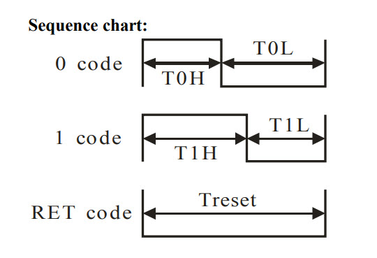
The values of these timings are shown in the following table:
| HIGH level timing for logic 0 | T0H | 0.5us | ±150ns |
| LOW level timing for logic 0 | T0L | 0.8us | ±150ns |
| HIGH level timing for logic 1 | T1H | 0.7us | ±150ns |
| LOW level timing for logic 1 | T1L | 0.6us | ±150ns |
| LOW level timing for RESET | TRST | > 50us |
This means that by sending logical 1 to the WS2812 device, the host MCU has to keep the data line HIGH for 0.7us then LOW for another 0.6us. Once the first 24bits are completed this way, the RST impulse will latch the data in.
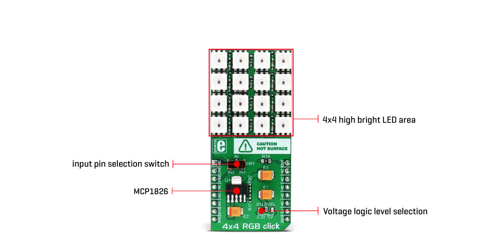
The communication line can be selected with the onboard SW1 switch. It offers a selection between the mikroBUS™ RST and CS lines, labelled as IN1 and IN2. The communication voltage level can be set by the onboard SMD jumper, labelled as the IO LEVEL and it can be chosen between 3.3V and 5V, allowing interfacing to both 3.3V and 5V MCUs.
The power supply for the LED elements is provided by the MCP1826 low-voltage, low quiescent current LDO regulator from Microchip, which can provide current up to 1A. While the logic voltage can be selected between 3.3V and 5V rails, the LED power supply is derived from the 5V mikroBUS™ power rail. It is reduced to 3.5V by the LDO, and distributed to the LED supply inputs of the WS2812 elements.
The PWM pin of the mikroBUS™, which is labelled as OUT on this Click board™, allows cascading of multiple 4x4 RGB click devices. It simply routes the data line back to the mikroBUS™, allowing it to be re-used for the next 4x4 RGB click, and so on. The length of the whole chain is limited only by the communication speed, required to scan through all the LED devices, in order to maintain a reasonable refresh speed.
A more detailed explanation of the data communication can be found in the WS2812 datasheet. However, the MikroElektronika provides a library that contains functions compatible with the MikroElektronika compilers, which can be used for simplified programming of the 4x4 RGB click. The library also contains an example application, which demonstrates their use. This example application can be used as a reference for custom designs.
| Type | LED Matrix |
| Applications | RGB Matrix display that can be used for many decorative functions, showing a different kinds of patterns or characters, or for providing a visual feedback |
| On-board modules | WS2812 - intelligent LED elements with integrated control, from the Worldsemi Corporation; MCP1826, a low-voltage LDO regulator from Microchip |
| Key Features | High brightness smart LED elements to allow display of various patterns in 16,777,216 different colours, data out pin for cascading additional devices, simplified programming with the included library functions |
| Interface | GPIO |
| Compatibility | mikroBUS |
| Click board size | L (57.15 x 25.4 mm) |
| Input Voltage | 3.3V or 5V |
This table shows how the pinout of the 4x4 RGB Click Board™ corresponds to the pinout on the mikroBUS™ socket (the latter shown in the two middle columns).
| Notes | Pin | Pin | Notes | ||||
|---|---|---|---|---|---|---|---|
| NC | 1 | AN | PWM | 16 | OUT | Output pin | |
| Data input 1 | IN1 | 2 | RST | INT | 15 | NC | |
| Data input 2 | IN2 | 3 | CS | RX | 14 | NC | |
| NC | 4 | SCK | TX | 13 | NC | ||
| NC | 5 | MISO | SCL | 12 | NC | ||
| NC | 6 | MOSI | SDA | 11 | NC | ||
| Power supply | 3.3V | 7 | 3.3V | 5V | 10 | 5V | Power supply |
| Ground | GND | 8 | GND | GND | 9 | GND | Ground |
| Label | Name | Default | Description |
|---|---|---|---|
| SW1 | SW1 | Right | Data Input selection jumper: left position IN2, right position IN1 |
| JP1 | IO level | Right | Voltage Logic Level Selection: left position 3.3V, right position 5V |
WS2812 is an intelligent control LED integrated light source which features a control circuit and a RGB chip, both integrated in a package of 5050 components. Apart from a 12V voltage programmable constant current control part and a precision internal oscillator, WS2812 also includes a signal reshaping amplification drive circuit and an intelligent digital port data latch.
MCP1826 is a 1A, ceramic output cap stable, Low Dropout Regulator (LDO). It features low output voltage, with shutdown and power good functions (fixed output version only). MCP1826 is part of the family of LDOs that includes 500 mA MCP1825 and 1.5A MCP1827. This Low Dropout Regulator is made available for you in thermally enhanced DDPAK-5 and TO-220-5 packages as well as space-efficient SOT223-5 package.
- amazon_main_image: https://www.thedebugstore.com/images/product/lg-mikroe-click-4x4-rgb.jpg - amazon_browse_node: 428655031 - related_products: MIKROE-2758,MIKROE-4331,MIKROE-1851 - mpn: MIKROE-1881 - backorder_label: If no stock shown above, check availability - badge: - widget:We provide a library for the 4x4 RGB Click Board™ on our LibStock page, as well as a demo application (example), developed using MikroElektronika compilers. The demo can run on all the main MikroElektronika development boards.
Library Description
The library performs control of the LED colour and light effects. Library uses LED colour control to perform some applications, like snake application in different colours and screen light also in different colours. The LED matrix on the 4x4 RGB click is connected to the target board microcontroller through the mikroBUS RST pin.
Key functions
void RGBLed_ZeroBit() - Determines logic low state for the LED diode.
void RGBLed_OneBit() - Determines logic high state for the LED diode.
void RGBLed_ResetDelay() - Reset function which includes the determined delay time.
void RGBLed_InitDiode(unsigned long ARGBColor, unsigned long * AdiodeArray) - Makes the array with values to set the desired diodes depending on the desired color.
void RGBLed_SetColor(unsigned long * AdiodeArray) - Uses marked array and functions for setting LED diode to a logic low or high state to set LED to the desired colour.
void RGBLed_SetDiode(char ANum, unsigned long AColor, unsigned long * AdiodeArray) - Turns the determined LED diode (ANum) to the desired colour by using SetColor function.
void RGBLed_InitHW() - Performs the hardware pin initialization.
void Delay_time() - Determines the time delay value.
void FillScreen() - Turns all LED diodes to the desired color.
Code snippet - Turns all LED diodes (fills all screen, LED matrix) to different colours with the delay time of 50 milliseconds.
The full application code, and ready to use projects can be found on our page.
void applicationTask()
{
 RGBLed_InitHW();
 TempColor = 0x002F2F2F; // White

 FillScreen();
 n=10; // 10*5ms = 50ms delay

 TempColor = 0x0000002F; // Blue color
 FillScreen();
 n=10;
 TempColor = 0x00002F2F; // Bright blue color
 FillScreen();
 n=10;
 TempColor = 0x00002F00; // Green colcor

 FillScreen();
 n=10;
 TempColor = 0x002F2F00; // Yellow color back
 FillScreen();
}
- attachments: [{"download_file":[{"download_file":"4X4 RGB Click Board™ Schematic"}],"download_filetype":[{"download_filetype":"pdf"}]},{"download_file":[{"download_file":"Worldsemi Corporation WS2812 Intelligent LED Element Datasheet"}],"download_filetype":[{"download_filetype":"pdf"}]},{"download_file":[{"download_file":"Microchip MCP1826 Low-Dropout Regulator Datasheet"}],"download_filetype":[{"download_filetype":"pdf"}]}]
- condition: new
- custom_product: false
- mpn: MIKROE-1881
- google_product_category: Electronics
- custom_label_0: Click Board
- device_vendor: Microchip Technology
- device_type: MCP1826T-ADJE/DC
- warranty: 12 months
- brand: MikroE
- manufacturer: Mikroelektronika d.o.o.
- brands: gid://shopify/Metaobject/56256004319
- breadcrumbs: ["gid://shopify/Collection/447955239135","gid://shopify/Collection/241680580797","gid://shopify/Collection/241544822973"]
- customhs_code: 847330
- detailed_description: {"type":"root","children":[{"type":"heading","level":3,"children":[{"type":"text","value":""}]},{"type":"paragraph","children":[{"type":"text","value":"Thanks to the high brightness of the LED elements and their colour consistency, the "},{"type":"text","value":"4x4 RGB Click Board™","bold":true},{"type":"text","value":" can be used in various decorative applications, simple pattern displays, colour number displays, and due to a cascade nature of the Click board™ itself, they can even be used for building larger screens and displays."}]},{"type":"paragraph","children":[{"type":"text","value":" "}]},{"type":"heading","level":3,"children":[{"type":"text","value":"How Does The 4x4 RGB Click Board™ Work?"}]},{"type":"paragraph","children":[{"type":"text","value":"The "},{"type":"text","value":"4x4 RGB Click Board™","bold":true},{"type":"text","value":" carries sixteen LED elements labelled as - intelligent LED elements with integrated control, from Worldsemi Corporation, arranged in a 4 by 4 matrix. These LED elements are composed of red, green, and blue LED segments, forming an RGB LED cell, with their intensities controlled by the integrated logic section. This integrated control section allows separate 8-bit control of each RGB segment, forming a 24-bit colour palette, allowing 16,777,216 different colours to be displayed."},{"type":"text","value":""},{"type":"text","value":""},{"type":"text","value":""}]},{"type":"paragraph","children":[{"type":"text","value":"The integrated logic communicates with the host MCU by a single line. The data transfer protocol uses the non-return-to-zero (NRZ) communication mode, so the timing of the data signal is critical. The logical 1 consists of a signal with a certain HIGH and LOW timing. The logical 0 also consists of a signal with a certain HIGH and LOW timing. The difference between logical 0 and 1 is in the timings of HIGH and LOW signal states, as illustrated in the picture below:"},{"type":"text","value":""},{"type":"text","value":""},{"type":"text","value":""}]},{"type":"paragraph","children":[{"type":"text","value":"The values of these timings are shown in the following table:"}]},{"type":"paragraph","children":[{"type":"text","value":"HIGH level timing for logic 0\nT0H\n0.5us\n±150ns\nLOW level timing for logic 0\nT0L\n0.8us\n±150ns\nHIGH level timing for logic 1\nT1H\n0.7us\n±150ns\nLOW level timing for logic 1\nT1L\n0.6us\n±150ns\nLOW level timing for RESET\nTRST\n> 50us"}]},{"type":"paragraph","children":[{"type":"text","value":"This means that by sending logical 1 to the WS2812 device, the host MCU has to keep the data line HIGH for 0.7us then LOW for another 0.6us. Once the first 24bits are completed this way, the RST impulse will latch the data in."}]},{"type":"paragraph","children":[{"type":"text","value":"The communication line can be selected with the onboard SW1 switch. It offers a selection between the mikroBUS™ RST and CS lines, labelled as IN1 and IN2. The communication voltage level can be set by the onboard SMD jumper, labelled as the IO LEVEL and it can be chosen between 3.3V and 5V, allowing interfacing to both 3.3V and 5V MCUs."},{"type":"text","value":""},{"type":"text","value":""},{"type":"text","value":""},{"type":"text","value":"The power supply for the LED elements is provided by the MCP1826 low-voltage, low quiescent current LDO regulator from Microchip, which can provide current up to 1A. While the logic voltage can be selected between 3.3V and 5V rails, the LED power supply is derived from the 5V mikroBUS™ power rail. It is reduced to 3.5V by the LDO, and distributed to the LED supply inputs of the WS2812 elements."}]},{"type":"paragraph","children":[{"type":"text","value":"The PWM pin of the mikroBUS™, which is labelled as OUT on this Click board™, allows cascading of multiple 4x4 RGB click devices. It simply routes the data line back to the mikroBUS™, allowing it to be re-used for the next 4x4 RGB click, and so on. The length of the whole chain is limited only by the communication speed, required to scan through all the LED devices, in order to maintain a reasonable refresh speed."}]},{"type":"paragraph","children":[{"type":"text","value":"A more detailed explanation of the data communication can be found in the WS2812 datasheet. However, the MikroElektronika provides a library that contains functions compatible with the MikroElektronika compilers, which can be used for simplified programming of the 4x4 RGB click. The library also contains an example application, which demonstrates their use. This example application can be used as a reference for custom designs."}]},{"type":"paragraph","children":[{"type":"text","value":" "}]},{"type":"heading","level":3,"children":[{"type":"text","value":"SPECIFICATIONS"}]},{"type":"paragraph","children":[{"type":"text","value":" "}]},{"type":"paragraph","children":[{"type":"text","value":"Type\nLED Matrix\nApplications\nRGB Matrix display that can be used for many decorative functions, showing a different kinds of patterns or characters, or for providing a visual feedback\nOn-board modules\nWS2812 - intelligent LED elements with integrated control, from the Worldsemi Corporation; MCP1826, a low-voltage LDO regulator from Microchip\nKey Features\nHigh brightness smart LED elements to allow display of various patterns in 16,777,216 different colours, data out pin for cascading additional devices, simplified programming with the included library functions\nInterface\nGPIO\nCompatibility\nmikroBUS\nClick board size\nL (57.15 x 25.4 mm)\nInput Voltage\n3.3V or 5V"}]},{"type":"paragraph","children":[{"type":"text","value":" "}]},{"type":"paragraph","children":[{"type":"text","value":" "}]},{"type":"heading","level":3,"children":[{"type":"text","value":"PINOUT DIAGRAM"}]},{"type":"paragraph","children":[{"type":"text","value":"This table shows how the pinout of the "},{"type":"text","value":"4x4 RGB Click Board™","bold":true},{"type":"text","value":" corresponds to the pinout on the mikroBUS™ socket (the latter shown in the two middle columns)."}]},{"type":"paragraph","children":[{"type":"text","value":"Notes\nPin\nPin\nNotes\nNC\n1\nAN\nPWM\n16\nOUT\nOutput pin\nData input 1\nIN1\n2\nRST\nINT\n15\nNC\nData input 2\nIN2\n3\nCS\nRX\n14\nNC\nNC\n4\nSCK\nTX\n13\nNC\nNC\n5\nMISO\nSCL\n12\nNC\nNC\n6\nMOSI\nSDA\n11\nNC\nPower supply\n3.3V\n7\n3.3V\n5V\n10\n5V\nPower supply\nGround\nGND\n8\nGND\nGND\n9\nGND\nGround"}]},{"type":"paragraph","children":[{"type":"text","value":" "}]},{"type":"heading","level":3,"children":[{"type":"text","value":"ONBOARD SETTINGS AND INDICATORS"}]},{"type":"paragraph","children":[{"type":"text","value":"Label\nName\nDefault\nDescription\nSW1\nSW1\nRight\nData Input selection jumper: left position IN2, right position IN1\nJP1\nIO level\nRight\nVoltage Logic Level Selection: left position 3.3V, right position 5V"}]},{"type":"paragraph","children":[{"type":"text","value":" "}]},{"type":"heading","level":3,"children":[{"type":"text","value":" "}]}]}
- summary: The 4x4 RGB Click Board™ is an add-on board that helps the user to add a colourful RGB LED matrix to the design. This accessory board comes equipped with a matrix of 16 very bright WS2812 RGB LEDs and an MCP1826 low dropout regulator. Each of these 16 LEDs further comprises three single coloured LEDs (Red, Green and Blue), and a control chip. Put together, there are a total of 48 individual LEDs in 4x4 RGB Click Board™. The control circuit and RGB chip have been integrated into a package of 5050 components to keep pixel points in complete control. 4x4 RGB Click Board™ features a jumper (zero Ω resistor) for setting the I/O logic level. It is by default soldered in the 3.3V position but can make use of either a 3.3V or 5V power supply. The LED matrix is connected to the target board microcontroller through the MikroBUS RST pin.
The 4x4 RGB Click Board™ can be used to create animations that can be scrolled on a computer screen. It is also usable for producing spellbinding displays of colourful graphics on electronic billboards, signs, and similar interfaces.
.