The L-Meter Click Board™ contains all the necessary components needed for a reliable measuring of coil inductance L, which in combination with host MCU makes it ideal in all applications where accurate inductance measuring is needed.Featuring four standard different SMD footprint size and two universal connectors for trought hole components, it's universal tool for any development.
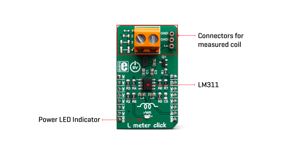
The principle how L meter Click Board™ works is very simple. In series with the measured coil is C1 capacitor, thus forming the LC circuit when the coil is present. The reference value on a high-speed voltage comparator LM311 is a half of the power supply voltage 2.5V. When the coil is added to the comparator input, the transistor briefly drops the coil to the ground, which is at on the half of the power voltage. The coil and the capacitor then start oscillating a resonant frequency that depends on the capacitor and the value of the coils. Since the capacitor has the fixed capacitance, the only variable is the inductance of the coil which can be calculated by:
2 * pi * F = 1 / sqrt (L * C)
This Click Board™ is designed to use only next mikroBUS pins: PWM output as a Trigger signal and INT – Hardware Interrupt that receive a square wave frequency output from Click Board™. Pins PWM and INT and are labelled as TS and FO, respectively. The board has two type of terminals for a coil connection: TB1 screws terminals and TS2 female header terminals. L meter Click Board™ also have four blank SMD places, to allow soldering different SMD coils for measuring directly onboard .
| Type | Measurements |
| Applications | It can be used to measure inductance as well as to check the accuracy and precision of the coil. |
| On-board modules | LM311D, a high-speed voltage comparator from Texas Instruments |
| Key Features | low-power consumption, high level of integration, simple use |
| Interface | GPIO |
| Compatibility | mikroBUS |
| Click Board™ size | M (42.9 x 25.4 mm) |
| Input Voltage | 5V |
This table shows how the pinout on L meter Click Board™ corresponds to the pinout on the mikroBUS socket (the latter shown in the two middle columns).
| Notes | Pin | Pin | Notes | ||||
|---|---|---|---|---|---|---|---|
| NC | 1 | AN | PWM | 16 | TS | Trigger switch | |
| NC | 2 | RST | INT | 15 | FO | Frequency out | |
| NC | 3 | CS | RX | 14 | NC | ||
| NC | 4 | SCK | TX | 13 | NC | ||
| NC | 5 | MISO | SCL | 12 | NC | ||
| NC | 6 | MOSI | SDA | 11 | NC | ||
| NC | 7 | 3.3V | 5V | 10 | 5V | Power Supply | |
| Ground | GND | 8 | GND | GND | 9 | GND | Ground |
| Label | Name | Default | Description |
|---|---|---|---|
| LD1 | PWR | - | Power LED Indicator |
| TB1 | Lx-IN | - | Inductor connector |
| TS2 | Lx-IN | - | Inductor connector |
L meter Click Board™
- amazon_main_image: https://www.thedebugstore.com/images/product/lg-l-meter-click-3505-front_1.jpg - amazon_other_image_1: https://www.thedebugstore.com/images/product/lg-l-meter-click-3505-back_1.jpg - amazon_other_image_2: https://www.thedebugstore.com/images/product/lg-l-meter-click-3505-in-use_1.jpg - amazon_other_image_3: https://www.thedebugstore.com/images/product/lg-l-meter-click-3505-in-use_1.jpg - amazon_browse_node: 428655031 - mpn: MIKROE-3505 - backorder_label: If no stock shown above, check availability - badge: - widget:We provide a library for the L meter Click Board™ on our LibStock page, as well as a demo application (example), developed using MikroElektronika compilers. The demo can run on all the main MikroElektronika development boards.
Library contains all the necessary functions for successfully reading Frequency and Inductance on the indicator.
uint32_t lmeter_getFrequency() - Frequency reading function.float lmeter_getCoilInductance() - Inductances reading function.void lmeter_tick() - Timer Tick functions.The application is composed of the three sections :
void applicationTask()
{
    uint8_t dataReady_;
    char receivedData_;

    dataReady_ = UART_Rdy_Ptr( );

    if (dataReady_ != 0)
    {
        receivedData_ = UART_Rd_Ptr( );

        switch (receivedData_)
        {
            case 'F' :
            {
                mikrobus_logWrite(" --- PLEASE WAIT FOR THE CALCULATION PROCESS TO COMPLETE ---", _LOG_LINE);
                lmeter_setTimer();
                _Frequency = lmeter_getFrequency();
                if (_Frequency < _LMETER_MIN_INDUCTANCE_RANGE)
                {
                    mikrobus_logWrite(" Frequency is out of range !!! ", _LOG_LINE);
                    mikrobus_logWrite("  ", _LOG_LINE);
                }
                else
                {
                    FloatToStr(_Frequency, demoText);
                    mikrobus_logWrite(" Frequency = ", _LOG_TEXT);
                    mikrobus_logWrite(demoText, _LOG_TEXT);
                    mikrobus_logWrite(" kHz ", _LOG_LINE);
                    mikrobus_logWrite("  ", _LOG_LINE);
                }
                break;
            }
            case 'L' :
            {
                mikrobus_logWrite(" --- PLEASE WAIT FOR THE CALCULATION PROCESS TO COMPLETE ---", _LOG_LINE);
                lmeter_setTimer();
                _Frequency = lmeter_getFrequency();

                if (_Frequency < _LMETER_MIN_INDUCTANCE_RANGE)
                {
                    mikrobus_logWrite(" Frequency is out of range !!! ", _LOG_LINE);
                    mikrobus_logWrite("  ", _LOG_LINE);
                }
                else
                {
                    _Inductance = lmeter_getCoilInductance(_Frequency);

                    FloatToStr(_Inductance, demoText);
                    mikrobus_logWrite(" Inductance = ", _LOG_TEXT);
                    mikrobus_logWrite(demoText, _LOG_TEXT);
                    mikrobus_logWrite(" uH ", _LOG_LINE);
                    mikrobus_logWrite("  ", _LOG_LINE);
                }
                break;
            }
            case 'T' :
            {
                if (T_SW == _LMETER_T_SW_ENABLE)
                {
                    T_SW = _LMETER_T_SW_DISABLE;
                    lmeter_setTSpin( _LMETER_T_SW_DISABLE );
                    mikrobus_logWrite(" ---  NEW SETTINGS - DISABLE [C2] CAPACITOR --- ", _LOG_LINE);
                    mikrobus_logWrite("* The sum of all the capacitors is 1000pF ", _LOG_LINE);
                    mikrobus_logWrite("* Disabled capacitor [C2]", _LOG_LINE);
                }
                else
                {
                    T_SW = _LMETER_T_SW_ENABLE;
                    lmeter_setTSpin( _LMETER_T_SW_ENABLE );
                    mikrobus_logWrite(" ---  NEW SETTINGS - ENABLE [C2] CAPACITOR --- ", _LOG_LINE);
                    mikrobus_logWrite("* The sum of all the capacitors is 500pF ", _LOG_LINE);
                    mikrobus_logWrite("* Active new capacitor [C2]", _LOG_LINE);
                }
                break;
            }
        }
    }
}
The full application code, and ready to use projects can be found on our LibStock page.
Other mikroE Libraries used in the example:
Conversions LibraryDepending on the development board you are using, you may need USB UART Click Board™, USB UART 2 Click Board™ or RS232 Click Board™ to connect to your PC, for development systems with no UART to USB interface available on the board. The terminal available in all MikroElektronika compilers, or any other terminal application of your choice, can be used to read the message.
This Click Board™ is supported with mikroSDK - MikroElektronika Software Development Kit. To ensure proper operation of mikroSDK compliant Click Board™ demo applications, mikroSDK should be downloaded from the LibStock and installed for the compiler you are using.
The online instant HTML beautifier tools make a great resource that will help you a lot in your work.
- attachments: [{"download_file":[{"download_file":"L Meter Click Board™ Schematic"}],"download_filetype":[{"download_filetype":"pdf"}]},{"download_file":[{"download_file":"Texas Instruments LM311 Voltage Comparator Datasheet"}],"download_filetype":[{"download_filetype":"pdf"}]}] - condition: new - custom_product: false - mpn: MIKROE-3505 - google_product_category: Electronics - custom_label_0: Click Board - device_vendor: Texas Instruments - device_type: LM311DR - warranty: 12 months - brand: MikroE - key_feature_1: Inductance Meter - manufacturer: Mikroelektronika d.o.o. - target_keyword: L Meter Click Board - brands: gid://shopify/Metaobject/56256004319 - breadcrumbs: ["gid://shopify/Collection/447955239135","gid://shopify/Collection/241680580797","gid://shopify/Collection/241545314493"] - customhs_code: 847330 - detailed_description: {"type":"root","children":[{"type":"paragraph","children":[{"type":"text","value":"The"},{"type":"text","value":" L-Meter Click Board™","bold":true},{"type":"text","value":" contains all the necessary components needed for a reliable measuring of coil inductance L, which in combination with host MCU makes it ideal in all applications where accurate inductance measuring is needed.Featuring four standard different SMD footprint size and two universal connectors for trought hole components, it's universal tool for any development."}]},{"type":"heading","level":3,"children":[{"type":"text","value":"How Does The L-Meter Click Board™ Work?"}]},{"type":"paragraph","children":[{"type":"text","value":"The principle how L meter Click Board™ works is very simple. In series with the measured coil is C1 capacitor, thus forming the LC circuit when the coil is present. The reference value on a high-speed voltage comparator LM311 is a half of the power supply voltage 2.5V. When the coil is added to the comparator input, the transistor briefly drops the coil to the ground, which is at on the half of the power voltage. The coil and the capacitor then start oscillating a resonant frequency that depends on the capacitor and the value of the coils. Since the capacitor has the fixed capacitance, the only variable is the inductance of the coil which can be calculated by:"},{"type":"text","value":""},{"type":"text","value":"2 * pi * F = 1 / sqrt (L * C)"}]},{"type":"paragraph","children":[{"type":"text","value":""}]},{"type":"paragraph","children":[{"type":"text","value":"This Click Board™ is designed to use only next mikroBUS pins: PWM output as a Trigger signal and INT – Hardware Interrupt that receive a square wave frequency output from Click Board™. Pins PWM and INT and are labelled as TS and FO, respectively. The board has two type of terminals for a coil connection: TB1 screws terminals and TS2 female header terminals. L meter Click Board™ also have four blank SMD places, to allow soldering different SMD coils for measuring directly onboard ."}]},{"type":"heading","level":3,"children":[{"type":"text","value":"SPECIFICATIONS"}]},{"type":"paragraph","children":[{"type":"text","value":" "}]},{"type":"paragraph","children":[{"type":"text","value":"Type\nMeasurements\nApplications\nIt can be used to measure inductance as well as to check the accuracy and precision of the coil.\nOn-board modules\nLM311D, a high-speed voltage comparator from Texas Instruments\nKey Features\nlow-power consumption, high level of integration, simple use\nInterface\nGPIO\nCompatibility\nmikroBUS\nClick Board™ size\nM (42.9 x 25.4 mm)\nInput Voltage\n5V"}]},{"type":"paragraph","children":[{"type":"text","value":" "}]},{"type":"heading","level":3,"children":[{"type":"text","value":"PINOUT DIAGRAM"}]},{"type":"paragraph","children":[{"type":"text","value":"This table shows how the pinout on L meter Click Board™ corresponds to the pinout on the mikroBUS socket (the latter shown in the two middle columns)."}]},{"type":"paragraph","children":[{"type":"text","value":"Notes\nPin\nPin\nNotes\nNC\n1\nAN\nPWM\n16\nTS\nTrigger switch\nNC\n2\nRST\nINT\n15\nFO\nFrequency out\nNC\n3\nCS\nRX\n14\nNC\nNC\n4\nSCK\nTX\n13\nNC\nNC\n5\nMISO\nSCL\n12\nNC\nNC\n6\nMOSI\nSDA\n11\nNC\nNC\n7\n3.3V\n5V\n10\n5V\nPower Supply\nGround\nGND\n8\nGND\nGND\n9\nGND\nGround"}]},{"type":"heading","level":3,"children":[{"type":"text","value":""},{"type":"text","value":"ONBOARD SETTINGS AND INDICATORS"}]},{"type":"paragraph","children":[{"type":"text","value":"Label\nName\nDefault\n Description\nLD1\nPWR\n-\nPower LED Indicator\nTB1\nLx-IN\n-\nInductor connector\nTS2\nLx-IN\n-\nInductor connector"}]},{"type":"heading","level":3,"children":[{"type":"text","value":" "}]}]} - summary:The L Meter Click Board™ is a compact and accurate Click Board™, capable of measuring and monitoring the inductance of the external component. The board can be used to measure a wide range of inductance. The design is based on a single high-speed voltage comparator LM311 by which the frequency of the oscillating LC circuit is measured and, based on the known value of capacitance, measures the unknown inductance value.
The L Meter Click Board™ can be used to measure inductance as well as to check the accuracy and precision of the coil.