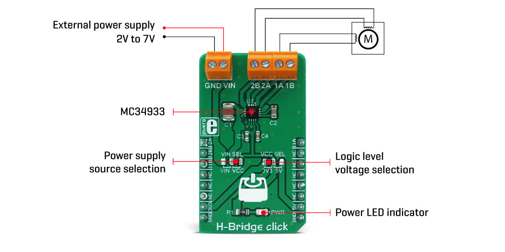
The H-Bridge Click Board™ uses the MC34933, a dual H-bridge driver, from NXP. This IC is a highly integrated device, which requires a minimal number of external elements. Each of the H-bridge channels features two high-side and two low-side MOSFETs, used to control the current flow through the coils of the motor. The driver IC is produced by using Freescale's proprietary SMARTMOS process, which ensures high efficiency and low power consumption. The total resistance across the output stage drivers is only 0.8Ω, allowing peak currents up to 1.5A, and 1A for the normal operation at 25˚C.
Driving H-bridge channels (and the connected load) is implemented by using four control input lines, two per channel. The truth table below illustrates how the control inputs affect the output stages. H-Bridge click can be used to drive bipolar step motors in full step or half-step mode, offering full control over the motor driving functions. The H-Bridge click can also be used for driving DC brushed motors. Special cases are when both control inputs of a single H-bridge channel are set to a HIGH or to a LOW logic state. In the first case, the output stage will be set to a high impedance (Hi-Z) mode. In the second case, both outputs of the H-bridge click will be tied up to the GND, discharging the remaining coil current, performing so-called rheostatic (dynamic) braking. The Hi-Z mode is also activated as a protection measure when the temperature is too high, or when the power supply voltage drops under a certain threshold.
The control inputs are routed to the mikroBUS™ pins for an easy connection with the MCU. IN1A and IN1B control pins of the MC34933 driver IC used to control the first H-bridge channel, are routed to the PWM and CS pins of the mikroBUS™ respectively, while the IN2A and IN2B control pins are routed to the AN and RST pins of the mikroBUS™. These pins are labelled as I1A, I2A, I1B, I2B, on the Click board™.
The power supply for the logic section of the IC is provided by the mikroBUS™ power rails. The ability of the driver IC to work with logic levels in the range of 3.3V to 5V simplifies the interfacing to MCUs that work with both voltages: it is enough to move the onboard SMD jumper labelled as VCC SEL, and select the desired logic voltage level between 3.3V and 5V.
The motor coils are supplied with the power from either the external power supply or by the mikroBUS™ power rail, selected with the VCC SEL jumper. When working with motors that consume more power than available at the mikroBUS™ power rail, it is advisable to connect the external power supply and move the jumper labelled as VIN SEL to the VIN position. By default, this jumper is set to use the mikroBUS™ power supply (VCC position). The external DC power supply can be connected to the two-pole input screw terminal, with its inputs labelled as GND and VIN. The stepper motor coils can be connected to the four-pole screw terminal, with its inputs labelled as 1A, 1B, 2A, 2B. These labels correspond to the H-bridge outputs from the driver IC itself: 1A is routed to the OUT1A, 1B to the OUT1B, and so on.
The H-Bridge Click Board™ can be easily driven via the GPIO pins of the host MCU. However, MikroElektronika provides a library that contains functions compatible with the MikroElektronika compilers, which can be used for simplified control of the H-Bridge click. Library offers functions for setting the rotation speed with selectable acceleration and deceleration, direction, half and full step driving mode, setting the output stages, and more. The library also contains an example application, which demonstrates the use of these functions. This example application can be used as a reference for custom designs.
| I1A/I2A | I1B/I2B | 1A/2A | 1B/2B |
|---|---|---|---|
| H | L | H | L |
| L | H | L | H |
| H | H | HI-Z | HI-Z |
| L | L | L | L |
| Type | Stepper |
| Applications | Driving of light 3D printer elements, for precision actuators, for an accurate positioning of various moving elements by using stepper motors, and similar applications. |
| On-board modules | MC34933, a dual H-bridge driver with 3V compatible logic inputs, from NXP. |
| Key Features | Low power consumption, under-voltage protection, thermal protection, shoot-through current suppression, simple stepper motor driving with four control pins, 3.3V and 5V compatible logic. |
| Interface | GPIO |
| Compatibility | mikroBUS |
| Click board size | M (42.9 x 25.4 mm) |
| Input Voltage | 3.3V or 5V |
This table shows how the pinout on the H-Bridge Click Board™ corresponds to the pinout on the mikroBUS™ socket (the latter shown in the two middle columns).
| Notes | Pin | Pin | Notes | ||||
|---|---|---|---|---|---|---|---|
| Logic input control 2A | IN2A | 1 | AN | PWM | 16 | IN1A | Logic input control 1A |
| Logic input control 2B | IN2B | 2 | RST | INT | 15 | NC | |
| Logic input control 1B | IN1B | 3 | CS | RX | 14 | NC | |
| NC | 4 | SCK | TX | 13 | NC | ||
| NC | 5 | MISO | SCL | 12 | NC | ||
| NC | 6 | MOSI | SDA | 11 | NC | ||
| Power Supply | +3V3 | 7 | 3.3V | 5V | 10 | +5V | Power Supply |
| Ground | GND | 8 | GND | GND | 9 | GND | Ground |
| Label | Name | Default | Description |
|---|---|---|---|
| JP1 | VCC SEL | Left | Logic level voltage selection: left position 3.3V, right position 5V |
| JP2 | VIN SEL | Right | Power supply source selection: left position VIN, right position VCC |
| LD1 | PWR | - | Power LED indicator |
| TB1 | 1A 1B | - | Terminal for connecting OUT1A and OUT1B |
| TB2 | 2A 2B | - | Terminal for connecting OUT2A and OUT2B |
| TB3 | VIN GND | - | Terminal for connecting input voltage VIN |
| Description | Min | Typ | Max | Unit |
|---|---|---|---|---|
| Voltage at the VIN terminal | 2 | 3.3 | 7 | V |
| Maximum load current (at 25°C) | - | 1 | - | A |
| VCC under-voltage threshold | 2.0 | 2.2 | 2.4 | V |
The H-Bridge click is a high-efficiency dual H-bridge driver Click board™, capable of providing reasonably high current while driving the connected load with up to 7V. Since the used driver IC has two full H-bridge channels, this Click board™ is an ideal solution for driving smaller bipolar stepper motors. H-Bridge click provides driving in both directions, with an addition of the brake mode, and the high impedance mode (Hi-Z). Overshoot current suppression algorithm protects the output stages from being damaged if both high-side and low-side MOSFETs on a single H-bridge channel become conductive.
Four control input lines allow independent control of the two H-bridge channels via the MCU. Featuring a set of protection and driving functions, this highly efficient Click board™ can be used in a wide range of applications, where driving smaller bipolar step motors or small brushed DC motors is required. It is an ideal solution for light 3D printer elements driving, for precision actuators, an accurate positioning of various moving elements by using stepper motors, and similar applications.
The Click board™ uses the MC34933, a dual H-bridge driver, from NXP. This IC is a highly integrated device, which requires a minimal number of external elements. Each of the H-bridge channels features two high-side and two low-side MOSFETs, used to control the current flow through the coils of the motor. The driver IC is produced by using the Freescale's proprietary SMARTMOS process, which ensures high efficiency and low power consumption. The total resistance across the output stage drivers is only 0.8Ω, allowing peak currents up to 1.5A, and 1A for the normal operation at 25˚C.
Driving H-bridge channels (and the connected load) is implemented by using four control input lines, two per channel. The truth table below illustrates how the control inputs affect the output stages. H-Bridge click can be used to drive bipolar step motors in full step or half-step mode, offering full control over the motor driving functions. The H-Bridge click can also be used for driving DC brushed motors. Special cases are when both control inputs of a single H-bridge channel are set to a HIGH or to a LOW logic state. In the first case, the output stage will be set to a high impedance (Hi-Z) mode. In the second case, both outputs of the H-bridge click will be tied up to the GND, discharging the remaining coil current, performing so-called rheostatic (dynamic) braking. The Hi-Z mode is also activated as a protection measure when the temperature is too high, or when the power supply voltage drops under a certain threshold.
The control inputs are routed to the mikroBUS™ pins for an easy connection with the MCU. IN1A and IN1B control pins of the MC34933 driver IC, used to control the first H-bridge channel, are routed to the PWM and CS pins of the mikroBUS™ respectively, while the IN2A and IN2B control pins are routed to the AN and RST pins of the mikroBUS™. These pins are labeled as I1A, I2A, I1B, I2B, on the Click board™.
The power supply for the logic section of the IC is provided by the mikroBUS™ power rails. The ability of the driver IC to work with logic levels in the range of 3.3V to 5V simplifies the interfacing to MCUs that work with both voltages: it is enough to move the onboard SMD jumper labeled as VCC SEL, and select the desired logic voltage level between 3.3V and 5V.
The motor coils are supplied with the power from either the external power supply, or by the mikroBUS™ power rail, selected with the VCC SEL jumper. When working with motors that consume more power than available at the mikroBUS™ power rail, it is advisable to connect the external power supply and move the jumper labeled as VIN SEL to the VIN position. By default, this jumper is set to use the mikroBUS™ power supply (VCC position). The external DC power supply can be connected to the two-pole input screw terminal, with its inputs labeled as GND and VIN. The stepper motor coils can be connected to the four-pole screw terminal, with its inputs labeled as 1A, 1B, 2A, 2B. These labels correspond to the H-bridge outputs from the driver IC itself: 1A is routed to the OUT1A, 1B to the OUT1B, and so on.
The Click board™ can be easily driven via the GPIO pins of the host MCU. However, MikroElektronika provides a library that contains functions compatible with the MikroElektronika compilers, which can be used for simplified control of the H-Bridge click. Library offers functions for setting the rotation speed with selectable acceleration and deceleration, direction, half and full step driving mode, setting the output stages, and more. The library also contains an example application, which demonstrates the use of these functions. This example application can be used as a reference for custom designs.
| I1A/I2A | I1B/I2B | 1A/2A | 1B/2B |
|---|---|---|---|
| H | L | H | L |
| L | H | L | H |
| H | H | HI-Z | HI-Z |
| L | L | L | L |
We provide a library for the H-Bridge Click Board™ on our Libstock page, as well as a demo application (example), developed using MikroElektronika compilers and mikroSDK. The provided click library is mikroSDK standard compliant. The demo application can run on all the main MikroElektronika development boards.
The library carries everything needed for stepper motor control including speed and acceleration setup. The library is also adjustable so that it's possible to work on a different amount of ticks per second. Also, speed and acceleration can be provided in float format. The buffer used for the movement calculation is defined by the user, so this library can be adjusted for MCUs with very limited RAM resources. Check the documentation for more details on how to use it.
uint8_t hbridge_setSpeed( float minSpeed, float maxSpeed, float accelRatio, T_HBRIDGE_OBJ obj ) - Setup motor speed.
uint8_t hbridge_setRoute( const uint8_t direction, uint32_t steps, T_HBRIDGE_OBJ obj ) - Setup new route.
void hbridge_start( T_HBRIDGE_OBJ obj ) - Starts the motor movement.
void hbridge_setOutput( uint8_t state ) - Function puts all four outputs in the desired state.
The application is composed of three sections:
void applicationTask()
{
 hbridge_start( (T_HBRIDGE_OBJ)&myStepper );
 while( myStepper.status.running )
 {
 hbridge_process( (T_HBRIDGE_OBJ)&myStepper );
 }
 Delay_ms( 1000 );
}
The full application code, and ready to use projects can be found on our Libstock page.
Depending on the development board you are using, you may need a USB UART click, USB UART 2 click or RS232 click to connect to your PC, for development systems with no UART to USB interface available on the board. The terminal available in all MikroElektronika compilers, or any other terminal application of your choice, can be used to read the message.
The H-Bridge Click Board™ is supported by mikroSDK - MikroElektronika Software Development Kit. To ensure proper operation of mikroSDK compliant Click board™ demo applications, mikroSDK should be downloaded from the LibStock and installed for the compiler you are using.
- attachments: [{"download_file":[{"download_file":"H-Bridge Click Board™ Schematic"}],"download_filetype":[{"download_filetype":"pdf"}]},{"download_file":[{"download_file":"NC{ MC34933 Dual H-Bridge Driver Datasheet"}],"download_filetype":[{"download_filetype":"pdf"}]}] - condition: new - custom_product: false - mpn: MIKROE-3031 - google_product_category: Electronics - custom_label_0: Click Board - device_vendor: NXP USA Inc. - device_type: MC34933EPR2 - warranty: 12 months - brand: MikroE - key_feature_1: Bipolar Stepper Motor Driver - manufacturer: Mikroelektronika d.o.o. - brands: gid://shopify/Metaobject/56256004319 - breadcrumbs: ["gid://shopify/Collection/447955239135","gid://shopify/Collection/241680580797","gid://shopify/Collection/241545248957","gid://shopify/Collection/279405232317"] - customhs_code: 847330 - detailed_description: {"type":"root","children":[{"type":"paragraph","children":[{"type":"text","value":"The "},{"type":"text","value":"H-Bridge Click Board™","bold":true},{"type":"text","value":" uses the MC34933, a dual H-bridge driver, from NXP. This IC is a highly integrated device, which requires a minimal number of external elements. Each of the H-bridge channels features two high-side and two low-side MOSFETs, used to control the current flow through the coils of the motor. The driver IC is produced by using Freescale's proprietary SMARTMOS process, which ensures high efficiency and low power consumption. The total resistance across the output stage drivers is only 0.8Ω, allowing peak currents up to 1.5A, and 1A for the normal operation at 25˚C."},{"type":"text","value":""},{"type":"text","value":""},{"type":"text","value":""}]},{"type":"paragraph","children":[{"type":"text","value":"Driving H-bridge channels (and the connected load) is implemented by using four control input lines, two per channel. The truth table below illustrates how the control inputs affect the output stages. H-Bridge click can be used to drive bipolar step motors in full step or half-step mode, offering full control over the motor driving functions. The H-Bridge click can also be used for driving DC brushed motors. Special cases are when both control inputs of a single H-bridge channel are set to a HIGH or to a LOW logic state. In the first case, the output stage will be set to a high impedance (Hi-Z) mode. In the second case, both outputs of the H-bridge click will be tied up to the GND, discharging the remaining coil current, performing so-called rheostatic (dynamic) braking. The Hi-Z mode is also activated as a protection measure when the temperature is too high, or when the power supply voltage drops under a certain threshold."}]},{"type":"paragraph","children":[{"type":"text","value":"The control inputs are routed to the mikroBUS™ pins for an easy connection with the MCU. IN1A and IN1B control pins of the MC34933 driver IC used to control the first H-bridge channel, are routed to the PWM and CS pins of the mikroBUS™ respectively, while the IN2A and IN2B control pins are routed to the AN and RST pins of the mikroBUS™. These pins are labelled as I1A, I2A, I1B, I2B, on the Click board™."}]},{"type":"paragraph","children":[{"type":"text","value":"The power supply for the logic section of the IC is provided by the mikroBUS™ power rails. The ability of the driver IC to work with logic levels in the range of 3.3V to 5V simplifies the interfacing to MCUs that work with both voltages: it is enough to move the onboard SMD jumper labelled as VCC SEL, and select the desired logic voltage level between 3.3V and 5V."}]},{"type":"paragraph","children":[{"type":"text","value":"The motor coils are supplied with the power from either the external power supply or by the mikroBUS™ power rail, selected with the VCC SEL jumper. When working with motors that consume more power than available at the mikroBUS™ power rail, it is advisable to connect the external power supply and move the jumper labelled as VIN SEL to the VIN position. By default, this jumper is set to use the mikroBUS™ power supply (VCC position). The external DC power supply can be connected to the two-pole input screw terminal, with its inputs labelled as GND and VIN. The stepper motor coils can be connected to the four-pole screw terminal, with its inputs labelled as 1A, 1B, 2A, 2B. These labels correspond to the H-bridge outputs from the driver IC itself: 1A is routed to the OUT1A, 1B to the OUT1B, and so on."}]},{"type":"paragraph","children":[{"type":"text","value":"The "},{"type":"text","value":"H-Bridge Click Board™","bold":true},{"type":"text","value":" can be easily driven via the GPIO pins of the host MCU. However, MikroElektronika provides a library that contains functions compatible with the MikroElektronika compilers, which can be used for simplified control of the H-Bridge click. Library offers functions for setting the rotation speed with selectable acceleration and deceleration, direction, half and full step driving mode, setting the output stages, and more. The library also contains an example application, which demonstrates the use of these functions. This example application can be used as a reference for custom designs."}]},{"type":"heading","level":3,"children":[{"type":"text","value":"Truth table"}]},{"type":"paragraph","children":[{"type":"text","value":"I1A/I2A\nI1B/I2B\n1A/2A\n1B/2B\nH\nL\nH\nL\nL\nH\nL\nH\nH\nH\nHI-Z\nHI-Z\nL\nL\nL\nL"}]},{"type":"heading","level":3,"children":[{"type":"text","value":"Specifications"}]},{"type":"paragraph","children":[{"type":"text","value":"Type\nStepper\nApplications\nDriving of light 3D printer elements, for precision actuators, for an accurate positioning of various moving elements by using stepper motors, and similar applications.\nOn-board modules\nMC34933, a dual H-bridge driver with 3V compatible logic inputs, from NXP.\nKey Features\nLow power consumption, under-voltage protection, thermal protection, shoot-through current suppression, simple stepper motor driving with four control pins, 3.3V and 5V compatible logic.\nInterface\nGPIO\nCompatibility\nmikroBUS\nClick board size\nM (42.9 x 25.4 mm)\nInput Voltage\n3.3V or 5V"}]},{"type":"heading","level":3,"children":[{"type":"text","value":"Pinout diagram"}]},{"type":"paragraph","children":[{"type":"text","value":"This table shows how the pinout on the "},{"type":"text","value":"H-Bridge Click Board™","bold":true},{"type":"text","value":" ","bold":true},{"type":"text","value":" corresponds to the pinout on the mikroBUS™ socket (the latter shown in the two middle columns)."}]},{"type":"paragraph","children":[{"type":"text","value":"Notes\nPin\nPin\nNotes\nLogic input control 2A\nIN2A\n1\nAN\nPWM\n16\nIN1A\nLogic input control 1A\nLogic input control 2B\nIN2B\n2\nRST\nINT\n15\nNC\nLogic input control 1B\nIN1B\n3\nCS\nRX\n14\nNC\nNC\n4\nSCK\nTX\n13\nNC\nNC\n5\nMISO\nSCL\n12\nNC\nNC\n6\nMOSI\nSDA\n11\nNC\nPower Supply\n+3V3\n7\n3.3V\n5V\n10\n+5V\nPower Supply\nGround\nGND\n8\nGND\nGND\n9\nGND\nGround"}]},{"type":"heading","level":3,"children":[{"type":"text","value":""},{"type":"text","value":"Onboard settings and indicators"}]},{"type":"paragraph","children":[{"type":"text","value":"Label\nName\nDefault\nDescription\nJP1\nVCC SEL\nLeft\nLogic level voltage selection: left position 3.3V, right position 5V\nJP2\nVIN SEL\nRight\nPower supply source selection: left position VIN, right position VCC\nLD1\nPWR\n-\nPower LED indicator\nTB1\n1A 1B\n-\nTerminal for connecting OUT1A and OUT1B\nTB2\n2A 2B\n-\nTerminal for connecting OUT2A and OUT2B\nTB3\nVIN GND\n-\nTerminal for connecting input voltage VIN"}]},{"type":"heading","level":3,"children":[{"type":"text","value":"H-Bridge click electrical specifications"}]},{"type":"paragraph","children":[{"type":"text","value":"Description\nMin\nTyp\nMax\nUnit\nVoltage at the VIN terminal\n2\n3.3\n7\nV\nMaximum load current (at 25°C) \n-\n1\n-\nA\nVCC under-voltage threshold\n2.0\n2.2\n2.4\nV"}]},{"type":"heading","level":3,"children":[{"type":"text","value":" "}]}]} - summary:The H-Bridge Click Board™ is a high-efficiency dual H-bridge driver capable of providing a reasonably high current while driving the connected load with up to 7V. Since the used driver IC has two full H-bridge channels, this Click Board™ is an ideal solution for driving smaller bipolar stepper motors.
The H-Bridge Click Board™ provides driving in both directions, with an addition of the brake mode, and the high impedance mode (Hi-Z). Overshoot current suppression algorithm protects the output stages from being damaged if both high-side and low-side MOSFETs on a single H-bridge channel become conductive.