# Title: Fan 3 Click Board™
## Description: A fan is a simple device that creates a flow within some fluid - such as the air, causing the heat accumulated in one section of the fluid to be moved away from the heat source, effectively cooling the affected area. The faster the fan rotates, the faster the fluid moves. This movement causes an audible noise which is one of the most obvious reasons why the fan speed control is needed, especially when the fan is used to cool down electronic components, such as the personal computer. How Does The Fan 3 Click Board™ Work? The Fan 3 Click Board™ uses two ICs to control the speed of the fan. The first IC is the MIC74 from Microchip, which is a serial to parallel I/O expander and fan controller. The four most significant bit outputs can be used to implement the fan speed control. This device uses an I2C communication protocol to set up the dedicated internal registers. The CLK and DATA pins are routed to mikroBUS™ I2C pins. Also, those pins are already pulled up with the 4k7 resistors on the click board, so there is no need to use additional pull-up resistors. The three most significant bit outputs are equipped with the resistors, connected to the feedback input (ADJ) of the MIC29152 IC - a high current, high accuracy, low dropout voltage regulator from Microchip. This regulator is used to output the regulated voltage for the fan, determined by the feedback voltage on the ADJ pin. The output of the regulator is set to 12V when the maximum speed is selected. The recommended input voltage should not be much higher than 12V because in that case, the regulating efficiency won't be optimal and the excess power will be dissipated as the heat. The voltage regulator features an internal power limiting logic, which protects it from damage in case of an excessive load on its output. Individual open-drain output bits of the MIC74 are selectively grounded or allowed to float under the control of the internal state machine, so the equivalent resistance seen by the MIC29152 regulator's feedback path is raised or lowered, changing the output voltage that way. The fourth bit is set to work as the SHDN which is used to enable the voltage regulator, via its EN pin when the fan mode is selected by the I2C. Setting this bit will activate the voltage regulator and the fan will start turning with the speed defined by the MIC74 registers. The Fan 3 Click Board™ can be used on several different I2C addresses, selectable by the ADD SEL jumpers. Those jumpers are used to directly set A0 to A2 address select pins of the MIC74. By default, all address pins are grounded, which sets the slave I2C address to 0x20h. The Fan 3 Click Board™ is equipped with two connectors. One connector is used to connect an external voltage source, which is fed to the input of the regulator. The other connector is used to connect the load - usually, an electromotor which works with the nominal voltage of 12V and has the fan blades attached to its rotor. MikroElektronika offers libraries with functions which allow simplified control over this click board. The example can also be used as a starting point or a reference for your own application code. SPECIFICATIONS Type Brushless Applications The Fan 3 Click Board™ can be used whenever a noiseless solution with the variable fan speed is needed, for example - cooling of electronic components with the minimal possible noise produced On-board modules MIC74 - 2-Wire Serial I/O Expander and Fan Controller and MIC29152 a high current, high accuracy, low dropout voltage regulator from Microchip Key Features Fan speed control circuit with 7 discrete voltage levels, which can deliver relatively high current on the output terminals. Over-current protection, I2C communication interface, several selectable I2C addresses Interface I2C Compatibility mikroBUS Click board size M (42.9 x 25.4 mm) Input Voltage 3.3V PINOUT DIAGRAM This table shows how the pinout on the Fan 3 Click Board™ corresponds to the pinout on the mikroBUS™ socket (the latter shown in the two middle columns). Notes Pin Pin Notes NC 1 AN PWM 16 NC NC 2 RST INT 15 NC NC 3 CS RX 14 NC NC 4 SCK TX 13 NC NC 5 MISO SCL 12 SCL I2C clock NC 6 MOSI SDA 11 SDA I2C data Power supply +3.3V 7 3.3V 5V 10 NC Ground GND 8 GND GND 9 GND Ground FAN 3 CLICK MAXIMUM RATINGS Description Min Typ Max Unit Input connector voltage 12 12 25 V ONBOARD SETTINGS AND INDICATORS Label Name Default Description LD1 PWR LED - Power indication LED JP1 ADD. SEL. LEFT Slave address least significant bit selection 0/1, left position 0, right position 1 JP2 ADD. SEL. LEFT Slave address second to least significant bit selection 0/1, left position 0, right position 1 JP3 ADD. SEL. LEFT Slave address third to least significant bit selection 0/1, left position 0, right position 1
## Product type: Click Board
## Vendor: Mikroelektronika d.o.o.
## Tags: Brushless, Click Board, Fan, MikroE, Motor Control
## Price range: 14.7 - 14.7 GBP
## Link: https://thedebugstore.com/products/fan-3-click-board-mikroe-2841-uk
## Compare-at price range: 21.0 - 21.0 GBP
## Options
- Title: Default Title
## Collections
- [New Products](https://thedebugstore.com/a/llms/collections/new-products-debug-store)
- [Mikroelektronika d.o.o. (MikroE)](https://thedebugstore.com/a/llms/collections/mikroelektronika-catalogue-uk)
- [Motor Control Click Boards™](https://thedebugstore.com/a/llms/collections/motor-control-click-boards-catalogue)
- [MikroE Click Boards™](https://thedebugstore.com/a/llms/collections/mikroe-click-boards-catalogue-uk)
- [Brushles Motor Control Click Boards™](https://thedebugstore.com/a/llms/collections/brushless-motor-control-click-boards-catalogue)
- [Click Boards™ Summer Sale](https://thedebugstore.com/a/llms/collections/inventory-sale)
- [MikroE Sale](https://thedebugstore.com/a/llms/collections/mikroe-sale)
- [MIKROE Stock](https://thedebugstore.com/a/llms/collections/mikroe-products-in-stock-sale)
## Variants
- Default Title, SKU: MIKROE-2841, Available: yes, Inventory: 1
## Metafields
- full_description: A fan is a simple device that creates a flow within some fluid - such as the air, causing the heat accumulated in one section of the fluid to be moved away from the heat source, effectively cooling the affected area. The faster the fan rotates, the faster the fluid moves. This movement causes an audible noise which is one of the most obvious reasons why the fan speed control is needed, especially when the fan is used to cool down electronic components, such as the personal computer.
How Does The Fan 3 Click Board™ Work?
The Fan 3 Click Board™ uses two ICs to control the speed of the fan. The first IC is the MIC74 from Microchip, which is a serial to parallel I/O expander and fan controller. The four most significant bit outputs can be used to implement the fan speed control. This device uses an I2C communication protocol to set up the dedicated internal registers. The CLK and DATA pins are routed to mikroBUS™ I2C pins. Also, those pins are already pulled up with the 4k7 resistors on the click board, so there is no need to use additional pull-up resistors.
The three most significant bit outputs are equipped with the resistors, connected to the feedback input (ADJ) of the MIC29152 IC - a high current, high accuracy, low dropout voltage regulator from Microchip. This regulator is used to output the regulated voltage for the fan, determined by the feedback voltage on the ADJ pin. The output of the regulator is set to 12V when the maximum speed is selected. The recommended input voltage should not be much higher than 12V because in that case, the regulating efficiency won't be optimal and the excess power will be dissipated as the heat. The voltage regulator features an internal power limiting logic, which protects it from damage in case of an excessive load on its output.
Individual open-drain output bits of the MIC74 are selectively grounded or allowed to float under the control of the internal state machine, so the equivalent resistance seen by the MIC29152 regulator's feedback path is raised or lowered, changing the output voltage that way. The fourth bit is set to work as the SHDN which is used to enable the voltage regulator, via its EN pin when the fan mode is selected by the I2C. Setting this bit will activate the voltage regulator and the fan will start turning with the speed defined by the MIC74 registers.
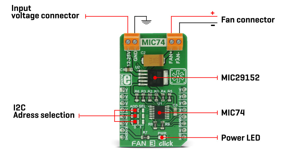
The Fan 3 Click Board™ can be used on several different I2C addresses, selectable by the ADD SEL jumpers. Those jumpers are used to directly set A0 to A2 address select pins of the MIC74. By default, all address pins are grounded, which sets the slave I2C address to 0x20h.
The Fan 3 Click Board™ is equipped with two connectors. One connector is used to connect an external voltage source, which is fed to the input of the regulator. The other connector is used to connect the load - usually, an electromotor which works with the nominal voltage of 12V and has the fan blades attached to its rotor.
MikroElektronika offers libraries with functions which allow simplified control over this click board. The example can also be used as a starting point or a reference for your own application code.
SPECIFICATIONS
| Type |
Brushless |
| Applications |
The Fan 3 Click Board™ can be used whenever a noiseless solution with the variable fan speed is needed, for example - cooling of electronic components with the minimal possible noise produced |
| On-board modules |
MIC74 - 2-Wire Serial I/O Expander and Fan Controller and MIC29152 a high current, high accuracy, low dropout voltage regulator from Microchip |
| Key Features |
Fan speed control circuit with 7 discrete voltage levels, which can deliver relatively high current on the output terminals. Over-current protection, I2C communication interface, several selectable I2C addresses |
| Interface |
I2C |
| Compatibility |
mikroBUS |
| Click board size |
M (42.9 x 25.4 mm) |
| Input Voltage |
3.3V |
PINOUT DIAGRAM
This table shows how the pinout on the Fan 3 Click Board™ corresponds to the pinout on the mikroBUS™ socket (the latter shown in the two middle columns).
| Notes |
Pin |
 |
Pin |
Notes |
| NC |
1 |
AN |
PWM |
16 |
NC |
| NC |
2 |
RST |
INT |
15 |
NC |
| NC |
3 |
CS |
RX |
14 |
NC |
| NC |
4 |
SCK |
TX |
13 |
NC |
| NC |
5 |
MISO |
SCL |
12 |
SCL |
I2C clock |
| NC |
6 |
MOSI |
SDA |
11 |
SDA |
I2C data |
| Power supply |
+3.3V |
7 |
3.3V |
5V |
10 |
NC |
| Ground |
GND |
8 |
GND |
GND |
9 |
GND |
Ground |
FAN 3 CLICK MAXIMUM RATINGS
| Description |
Min |
Typ |
Max |
Unit |
| Input connector voltage |
12 |
12 |
25 |
V |
ONBOARD SETTINGS AND INDICATORS
| Label |
Name |
Default |
Description |
| LD1 |
PWR LED |
- |
Power indication LED |
| JP1 |
ADD. SEL. |
LEFT |
Slave address least significant bit selection 0/1, left position 0, right position 1 |
| JP2 |
ADD. SEL. |
LEFT |
Slave address second to least significant bit selection 0/1, left position 0, right position 1 |
| JP3 |
ADD. SEL. |
LEFT |
Slave address third to least significant bit selection 0/1, left position 0, right position 1 |
- description_tag: The Fan 3 Click Board™ is the perfect choice for speed control and it can operate in seven discrete speed steps. Available from Debug Store UK.
- title_tag: MikroE Fan 3 Click Board™ (MIKROE-2841)
- manufacturer: Mikroelektronika d.o.o.
- warranty: 12 months
- amazon_enable: TRUE
- amazon_title: Fan 3 Click Board
- amazon_product_type: computercomponent
- amazon_block: FALSE
- amazon_prime_enable: FALSE
- amazon_search: MikroElektronika Microelectronica MIKROE-1100
- amazon_uk_price: 15.75
- amazon_uk_currency: GBP
- amazon_de_currency: EUR
- amazon_de_price: 17.7975
- amazon_fr_currency: EUR
- amazon_fr_price: 17.7975
- amazon_es_currency: EUR
- amazon_es_price: 17.7975
- amazon_nl_currency: EUR
- amazon_nl_price: 17.7975
- amazon_it_currency: EUR
- amazon_it_price: 17.7975
- amazon_se_curency: SEK
- amazon_se_price: 179.55
- amazon_product_id: 8606018712076
- amazon_product_id_type: EAN
- amazon_update: Update
- amazon_short_description: The Fan 3 Click Board™ is the perfect choice for speed control and it can operate in seven discrete speed steps. Unlike the PWM regulation which can sometimes cause the infamous coil whining effect on some types of fans, this Click Board™ outputs the selected voltage via the MIC29152 voltage regulator from Microchip, driven through the MIC74 - a serial to parallel I/O expander and a fan controller from the same company, keeping it constant at the output. Fan 3 Click Board™ works with 12V to 25V on its input connector and can be used whenever a noiseless solution with a variable fan speed is needed, for example - cooling of electronic components with the minimal possible noise produced.
- amazon_long_description: A fan is a simple device that creates a flow within some fluid - such as the air, causing the heat accumulated in one section of the fluid to be moved away from the heat source, effectively cooling the affected area. The faster the fan rotates, the faster the fluid moves. This movement causes an audible noise which is one of the most obvious reasons why the fan speed control is needed, especially when the fan is used to cool down electronic components, such as the personal computer.Fan 3 Click is the perfect choice for speed control and it can operate in seven discrete speed steps. Unlike the PWM regulation which can sometimes cause the infamous coil whining effect on some types of fans, this Click Board™ outputs the selected voltage via the MIC29152 voltage regulator from Microchip, driven through the MIC74 - a serial to parallel I/O expander and a fan controller from the same company, keeping it constant at the output. Fan 3 Click works with 12V to 25V on its input connector and can be used whenever a noiseless solution with a variable fan speed is needed, for example - cooling of electronic components with the minimal possible noise produced.
How Does it Work?
The Fan 3 Click uses two ICs to control the speed of the fan. The first IC is the MIC74 from Microchip, which is a serial to parallel I/O expander and fan controller. The four most significant bit outputs can be used to implement the fan speed control. This device uses an I2C communication protocol to set up the dedicated internal registers. The CLK and DATA pins are routed to mikroBUS I2C pins. Also, those pins are already pulled up with the 4k7 resistors on the Click Board™, so there is no need to use additional pull-up resistors. The three most significant bit outputs are equipped with the resistors, connected to the feedback input (ADJ) of the MIC29152 IC - a high current, high accuracy, low dropout voltage regulator from Microchip. This regulator is used to output the regulated voltage for the fan, determined by the feedback voltage on the ADJ pin. The output of the regulator is set to 12V when the maximum speed is selected. The recommended input voltage should not be much higher than 12V because in that case, the regulating efficiency won't be optimal and the excess power will be dissipated as the heat. The voltage regulator features an internal power limiting logic, which protects it from damage in case of an excessive load on its output.
Individual open-drain output bits of the MIC74 are selectively grounded or allowed to float under the control of the internal state machine, so the equivalent resistance seen by the MIC29152 regulator's feedback path is raised or lowered, changing the output voltage that way. The fourth bit is set to work as the SHDN which is used to enable the voltage regulator, via its EN pin when the fan mode is selected by the I2C. Setting this bit will activate the voltage regulator and the fan will start turning with the speed defined by the MIC74 registers. Fan 3 Click can be used on several different I2C addresses, selectable by the ADD SEL jumpers. Those jumpers are used to directly set A0 to A2 address select pins of the MIC74. By default, all address pins are grounded, which sets the slave I2C address to 0x20h.
The Click is equipped with two connectors. One connector is used to connect an external voltage source, which is fed to the input of the regulator. The other connector is used to connect the load - usually, an electromotor which works with the nominal voltage of 12V and has the fan blades attached to its rotor.
MikroElektronika offers libraries with functions which allow simplified control over this Click Board™. The example can also be used as a starting point or a reference for your own application code.
- amazon_main_image: https://www.thedebugstore.com/images/product/lg-fan-3-click-board.jpg
- amazon_browse_node: 428655031
- mpn: MIKROE-2841
- backorder_label: If no stock shown above, check availability
- badge: No reviews
- widget:
- examples: Software Support
We provide a library for the Fan 3 Click Board™ on our LibStock page, as well as a demo application (example), developed using MikroElektronika compilers. The demo can run on all the main MikroElektronika development boards.
Library Description
The library contains a function that controls the operation of the Fan 3 Click Board™.
Key functions
void fan3_setSpeed(uint8_t newSpeed) - Controls the fan speed
Example Description
The application is composed of three sections :
- System Initialization - Initializes I2C peripheral and UART logger.
- Application Initialization - Initializes the click driver.
- Application Task - (Code snippet) Cycles through different fan speeds, including 0 - stopped.
    mikrobus_logWrite("Speed 1...",_LOG_LINE);
    fan3_setSpeed(_FAN3_SPEED1);
    Delay_ms( 4000 );
    mikrobus_logWrite("Speed 3...",_LOG_LINE);
    fan3_setSpeed(_FAN3_SPEED3);
    Delay_ms( 4000 );
    mikrobus_logWrite("Speed 5...",_LOG_LINE);
    fan3_setSpeed(_FAN3_SPEED5);
    Delay_ms( 4000 );
    mikrobus_logWrite("Speed 7...",_LOG_LINE);
    fan3_setSpeed(_FAN3_SPEED7);
    Delay_ms( 4000 );
    mikrobus_logWrite("Stopped...",_LOG_LINE);
    fan3_setSpeed(_FAN3_STOPPED);
    Delay_ms( 4000 );
The full application code, and ready to use projects can be found on our LibStock page.
Other MikroElektronika libraries used in the example:
Additional Notes and Information
Depending on the development board you are using, you may need a USB UART click, USB UART 2 click or RS232 click to connect to your PC, for development systems with no UART to USB interface available on the board. The terminal available in all MikroElektronika compilers, or any other terminal application of your choice, can be used to read the message.
MIKROSDK
The Fan 3 Click Board™ is supported with mikroSDK, the MikroElektronika Software Development Kit.
- attachments: [{"download_file":[{"download_file":"Fan 3 Click Board™ Schematic"}],"download_filetype":[{"download_filetype":"pdf"}]},{"download_file":[{"download_file":"Microchip MIC74 Fan Controller Datasheet"}],"download_filetype":[{"download_filetype":"pdf"}]}]
- condition: new
- custom_product: false
- mpn: MIKROE-2841
- google_product_category: Electronics
- custom_label_0: Click Board
- device_vendor: Microchip Technology
- device_type: MIC29152WD-TR, MIC74YQS
- warranty: 12 months
- brand: MikroE
- manufacturer: Mikroelektronika d.o.o.
- brands: gid://shopify/Metaobject/56256004319
- breadcrumbs: ["gid://shopify/Collection/447955239135","gid://shopify/Collection/241680580797","gid://shopify/Collection/241545248957","gid://shopify/Collection/279405199549"]
- customhs_code: 847330
- detailed_description: {"type":"root","children":[{"type":"paragraph","children":[{"type":"text","value":"A fan is a simple device that creates a flow within some fluid - such as the air, causing the heat accumulated in one section of the fluid to be moved away from the heat source, effectively cooling the affected area. The faster the fan rotates, the faster the fluid moves. This movement causes an audible noise which is one of the most obvious reasons why the fan speed control is needed, especially when the fan is used to cool down electronic components, such as the personal computer."}]},{"type":"heading","level":3,"children":[{"type":"text","value":"How Does The Fan 3 Click Board™ Work?"}]},{"type":"paragraph","children":[{"type":"text","value":"The "},{"type":"text","value":"Fan 3 Click Board™ ","bold":true},{"type":"text","value":"uses two ICs to control the speed of the fan. The first IC is the MIC74 from Microchip, which is a serial to parallel I/O expander and fan controller. The four most significant bit outputs can be used to implement the fan speed control. This device uses an I2C communication protocol to set up the dedicated internal registers. The CLK and DATA pins are routed to mikroBUS™ I2C pins. Also, those pins are already pulled up with the 4k7 resistors on the click board, so there is no need to use additional pull-up resistors."},{"type":"text","value":""},{"type":"text","value":""},{"type":"text","value":""},{"type":"text","value":"The three most significant bit outputs are equipped with the resistors, connected to the feedback input (ADJ) of the MIC29152 IC - a high current, high accuracy, low dropout voltage regulator from Microchip. This regulator is used to output the regulated voltage for the fan, determined by the feedback voltage on the ADJ pin. The output of the regulator is set to 12V when the maximum speed is selected. The recommended input voltage should not be much higher than 12V because in that case, the regulating efficiency won't be optimal and the excess power will be dissipated as the heat. The voltage regulator features an internal power limiting logic, which protects it from damage in case of an excessive load on its output. "},{"type":"text","value":""},{"type":"text","value":""},{"type":"text","value":""},{"type":"text","value":"Individual open-drain output bits of the MIC74 are selectively grounded or allowed to float under the control of the internal state machine, so the equivalent resistance seen by the MIC29152 regulator's feedback path is raised or lowered, changing the output voltage that way. The fourth bit is set to work as the SHDN which is used to enable the voltage regulator, via its EN pin when the fan mode is selected by the I2C. Setting this bit will activate the voltage regulator and the fan will start turning with the speed defined by the MIC74 registers."},{"type":"text","value":""},{"type":"text","value":""},{"type":"text","value":""},{"type":"text","value":""},{"type":"text","value":""},{"type":"text","value":""},{"type":"text","value":"The "},{"type":"text","value":"Fan 3 Click Board™","bold":true},{"type":"text","value":" can be used on several different I2C addresses, selectable by the ADD SEL jumpers. Those jumpers are used to directly set A0 to A2 address select pins of the MIC74. By default, all address pins are grounded, which sets the slave I2C address to 0x20h."},{"type":"text","value":""},{"type":"text","value":""},{"type":"text","value":""},{"type":"text","value":"The "},{"type":"text","value":"Fan 3 Click Board™","bold":true},{"type":"text","value":" is equipped with two connectors. One connector is used to connect an external voltage source, which is fed to the input of the regulator. The other connector is used to connect the load - usually, an electromotor which works with the nominal voltage of 12V and has the fan blades attached to its rotor."},{"type":"text","value":""},{"type":"text","value":""},{"type":"text","value":""},{"type":"text","value":"MikroElektronika offers libraries with functions which allow simplified control over this click board. The example can also be used as a starting point or a reference for your own application code."}]},{"type":"heading","level":3,"children":[{"type":"text","value":"SPECIFICATIONS"}]},{"type":"paragraph","children":[{"type":"text","value":"Type\nBrushless\nApplications\nThe Fan 3 Click Board™ can be used whenever a noiseless solution with the variable fan speed is needed, for example - cooling of electronic components with the minimal possible noise produced\nOn-board modules\nMIC74 - 2-Wire Serial I/O Expander and Fan Controller and MIC29152 a high current, high accuracy, low dropout voltage regulator from Microchip\nKey Features\nFan speed control circuit with 7 discrete voltage levels, which can deliver relatively high current on the output terminals. Over-current protection, I2C communication interface, several selectable I2C addresses\nInterface\nI2C\nCompatibility\nmikroBUS\nClick board size\nM (42.9 x 25.4 mm)\nInput Voltage\n3.3V"}]},{"type":"heading","level":3,"children":[{"type":"text","value":""},{"type":"text","value":"PINOUT DIAGRAM "}]},{"type":"paragraph","children":[{"type":"text","value":"This table shows how the pinout on the "},{"type":"text","value":"Fan 3 Click Board™","bold":true},{"type":"text","value":" corresponds to the pinout on the mikroBUS™ socket (the latter shown in the two middle columns)."},{"type":"text","value":""},{"type":"text","value":" "}]},{"type":"paragraph","children":[{"type":"text","value":"Notes\nPin\nPin\nNotes\nNC\n1\nAN\nPWM\n16\nNC\nNC\n2\nRST\nINT\n15\nNC\nNC\n3\nCS\nRX\n14\nNC\nNC\n4\nSCK\nTX\n13\nNC\nNC\n5\nMISO\nSCL\n12\nSCL\nI2C clock\nNC\n6\nMOSI\nSDA\n11\nSDA\nI2C data\nPower supply\n+3.3V\n7\n3.3V\n5V\n10\nNC\nGround\nGND\n8\nGND\nGND\n9\nGND\nGround"}]},{"type":"heading","level":3,"children":[{"type":"text","value":"FAN 3 CLICK MAXIMUM RATINGS"}]},{"type":"paragraph","children":[{"type":"text","value":"Description\nMin\nTyp\nMax\nUnit\nInput connector voltage\n12\n12\n25\nV"}]},{"type":"heading","level":3,"children":[{"type":"text","value":"ONBOARD SETTINGS AND INDICATORS"}]},{"type":"paragraph","children":[{"type":"text","value":"Label\nName\nDefault\n Description\nLD1\nPWR LED\n-\nPower indication LED\nJP1\nADD. SEL.\nLEFT\nSlave address least significant bit selection 0/1, left position 0, right position 1\nJP2\nADD. SEL.\nLEFT\nSlave address second to least significant bit selection 0/1, left position 0, right position 1\nJP3\nADD. SEL.\nLEFT\nSlave address third to least significant bit selection 0/1, left position 0, right position 1"}]},{"type":"heading","level":3,"children":[{"type":"text","value":" "}]}]}
- summary: The Fan 3 Click Board™ is the perfect choice for speed control and it can operate in seven discrete speed steps. Unlike the PWM regulation which can sometimes cause the infamous coil whining effect on some types of fans, this Click Board™ outputs the selected voltage via the MIC29152 voltage regulator from Microchip, driven through the MIC74 - a serial to parallel I/O expander and a fan controller from the same company, keeping it constant at the output.
The Fan 3 Click Board™ works with 12V to 25V on its input connector and can be used whenever a noiseless solution with a variable fan speed is needed, for example - cooling of electronic components with the minimal possible noise produced.