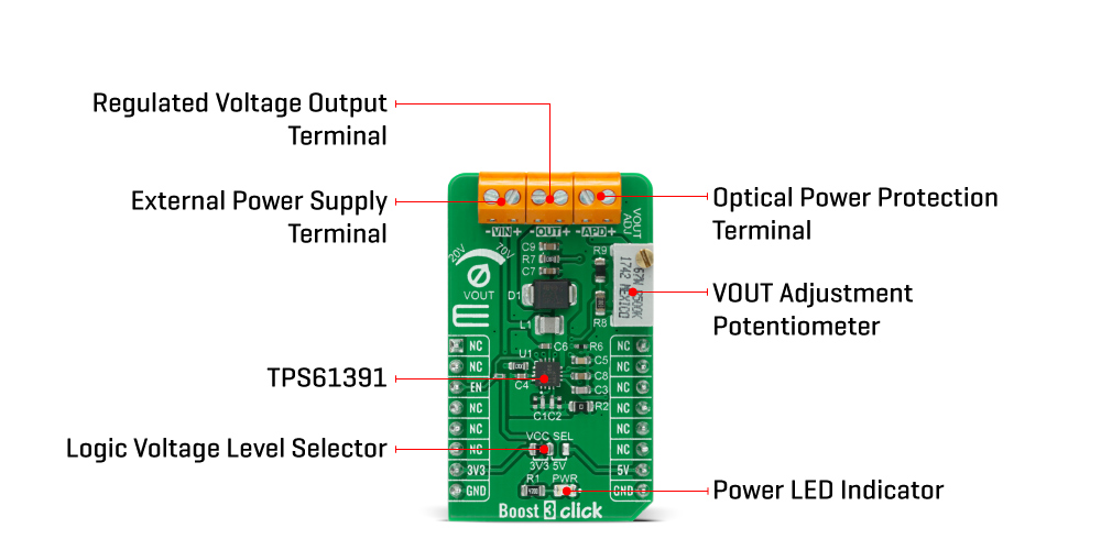
The Boost 3 Click Board™ is based on the TPS61391, a 700-kHz pulse-width modulating (PWM) Step-Up converter with a 70V switch FET with an input voltage up to 5.5 V from Texas Instruments. It supports an input voltage up to 5.5V and operates at a 700 kHz pulse-width modulation (PWM) crossing the whole load range. There are two ratio options for the current proportional to the APD current: MON1 (4:5) and MON2 (1:5). By connecting an additional RC filter for low ripple applications from the mirror output pins to the GND, the current flowing through the APD is converted into the voltage crossing the resistor from MON1/MON2 pins to GND. Additionally, a high power optical protection, with the response time typically of 0.5 μs, is integrated by clamping the pre-set current limit (program by the R6 resistor) and could recover automatically when the high optical power is removed.
The output voltage of the TPS61391 is externally adjustable using a resistor divider network. The relationship between the output voltage and the resistor divider is given by the equation:
VOUT = ( VREF + 0.1V ) * ( 1 + ( VR1 + R8 ) / R9 ) [V]
where VREF has a typical value of 1.2V. When the potentiometer has a 0V value, the output voltage has its minimum value of 20V. Increasing the resistance of a potentiometer and reaching its maximum value of 500kΩ, the output voltage also reaches its maximum value of 70V. The potentiometer featured on the Boost 3 Click Board™ can change the feedback thus influencing a change in the output voltage. This makes the Click board™ extremely practical because you can, with a simple turn of the potentiometer, get the wide voltage range.
The Boost 3 Click Board™ communicates with MCU using only one GPIO pin routed on the CS pin of the mikroBUS™ socket labeled as EN. An under-voltage lockout (UVLO) circuit stops the operation of the converter when the input voltage drops below the typical UVLO threshold of 2.5 V. When the input voltage is above the maximal UVLO rising threshold of 2.5 V, and the EN pin is pulled above the high threshold (1.2V minimum), the TPS61391 is enabled. When the EN pin is pulled below the low threshold (0.4 maximum), the device goes into Shutdown Mode.
It also possesses the output terminal labeled as APD used for biasing and monitoring the avalanche photodiodes (APD) and high optical power protection. There is an additional FET in series of power path connecting with the APD output terminal. When the current flowing through the external APD exceeds the short protection threshold, set by connecting the resistor from R6 to the ground, the on-resistance of the internal FET becomes larger to clamp the current within the protection threshold by lowering the APD bias voltage. It takes typically 0.5μs for the FET to respond in case of high optical power occurring. When the high optical power condition releases, the TPS61391 recovers automatically back to the Normal Operation Mode.
The Boost 3 Click Board™ is designed to be operated with both 3.3V and 5V logic voltage levels that can be selected via VCC SEL jumper. This allows for both 3.3V and 5V capable MCUs to use the GPIO communication line properly. However, the Click board™ comes equipped with a library that contains easy to use functions and an example code that can be used as a reference for further development.
| Type | Boost |
| Applications | Can be used for applications such as biasing and monitoring the avalanche photodiodes (APD) in the optical receivers, but it also can be used as a high voltage sensor supply or in battery-powered and automotive applications. |
| On-board modules | The Boost 3 Click Board™ is based on the TPS61391, a 700-kHz pulse-width modulating (PWM) Step-Up converter with a 70V switch FET with an input voltage up to 5.5 V from Texas Instruments. |
| Key Features | An under-voltage lockout, high optical power protection, wide output voltage range from 20V to 70V, current mirror function, and more. |
| Interface | GPIO |
| Compatibility | mikroBUS |
| Click board size | M (42.9 x 25.4 mm) |
| Input Voltage | 3.3V or 5V |
This table shows how the pinout of the Boost 3 Click Board™ corresponds to the pinout on the mikroBUS™ socket (the latter shown in the two middle columns).
| Notes | Pin | Pin | Notes | ||||
|---|---|---|---|---|---|---|---|
| NC | 1 | AN | PWM | 16 | NC | ||
| NC | 2 | RST | INT | 15 | NC | ||
| Device Enable | CS | 3 | CS | RX | 14 | NC | |
| NC | 4 | SCK | TX | 13 | NC | ||
| NC | 5 | MISO | SCL | 12 | NC | ||
| NC | 6 | MOSI | SDA | 11 | NC | ||
| Power Supply | 3.3V | 7 | 3.3V | 5V | 10 | 5V | Power Supply |
| Ground | GND | 8 | GND | GND | 9 | GND | Ground |
| Label | Name | Default | Description |
|---|---|---|---|
| LD1 | PWR | - | Power LED Indicator |
| JP1 | VCC SEL | Left | Power Supply Voltage Selection 3V3/5V: Left position 3V3, Right position 5V |
| VR1 | VOUT ADJ | - | VOUT Adjustment Potentiometer |
| Description | Min | Typ | Max | Unit |
|---|---|---|---|---|
| Input Voltage | 2.5 | - | 5.5 | V |
| High Optical Power Current Limit ( RISHORT=25kΩ ) | 3.7 | 4 | 4.3 | mA |
| Feedback Regulation Reference Voltage | 1.182 | 1.2 | 1.218 | V |
| Switching Frequency | 600 | 700 | 800 | kHz |
| Operating Temperature Range | -40 | - | +125 | °C |
The Boost 4 Click Board™ carries the TPS61230A, a high efficiency fully integrated synchronous boost converter from Texas Instruments. The Click is designed to run on a 3.3V power supply. Boost 4 Click drives the target chip through the digi pot, which has SPI communication with the microcontroller on the system.
Boost 4 Click is the power management solution for your next project.
Boost 4 Click provides an adjustable output voltage through the SPI DAC, that drives the FB pin to set desired voltage. The Click is capable of delivering up to 2.4-A output current at a 5V output with the 2.5-V input supply.
The TPS61230A device is a high efficiency fully integrated synchronous boost converter. It integrates 6-A, 21-mΩ and 18-mΩ power switches.
During the light load condition, the TPS61230A automatically enters into the PFM operation for maximizing the efficiency with the lowest quiescent current. In the shutdown by pulling EN pin to the logic low, the load is completely disconnected from the input, and the input current consumption is reduced to below 1.0 A.
- amazon_main_image: https://www.thedebugstore.com/images/product/lg-boost-3-click-front.jpg - amazon_other_image_1: https://www.thedebugstore.com/images/product/lg-boost-3-click-back.jpg - amazon_other_image_2: https://www.thedebugstore.com/images/product/lg-boost-3-click-fusion.jpg - amazon_other_image_3: https://www.thedebugstore.com/images/product/lg-boost-3-click-shuttle.jpg - amazon_other_image_4: https://www.thedebugstore.com/images/product/lg-boost-3-click-clicker.jpg - amazon_other_image_5: https://www.thedebugstore.com/images/product/lg-boost-3-click-breadboard.jpg - amazon_other_image_6: https://www.thedebugstore.com/images/product/lg-boost-3-click-breadboard.jpg - amazon_browse_node: 428655031 - related_products: MIKROE-1592 - mpn: MIKROE-4287 - backorder_label: If no stock shown above, check availability - badge: - widget:We provide a library for the Boost 3 Click Board™ on our LibStock page, as well as a demo application (example), developed using MikroElektronika compilers. The demo can run on all the main MikroElektronika development boards.
The library covers the necessary function that enables the usage of the Boost 3 Click Board™. User can enable or disable the device.
void boost3_dev_enable ( uint8_t state ); - Function is used to enable or disable the device.The application is composed of three sections :
void application_task ( )
{
    char cmd;
    if ( UART_Rdy_Ptr() )
    {
        cmd = UART_Rd_Ptr( );
        cmd -= 48;
        boost3_dev_enable( cmd );
        if( cmd == BOOST3_ENABLE )
        {
            mikrobus_logWrite( "The device is turned on!", _LOG_LINE );
            mikrobus_logWrite( "Use on-board potentiometer", _LOG_LINE );
            mikrobus_logWrite( " to adjust 'Vout' voltage", _LOG_LINE );
        }
        else
        {
            mikrobus_logWrite( "The device is turned off!", _LOG_LINE );
        }
    }
}
The full application code, and ready to use projects can be found on our LibStock page.
Other mikroE Libraries used in the example:
Depending on the development board you are using, you may need a USB UART click, USB UART 2 click or RS232 click to connect to your PC, for development systems with no UART to USB interface available on the board. The terminal available in all MikroElektronika compilers, or any other terminal application of your choice, can be used to read the message.
The Boost 3 Click Board™ is supported with mikroSDK - MikroElektronika Software Development Kit. To ensure proper operation of mikroSDK compliant Click board™ demo applications, mikroSDK should be downloaded from the LibStock and installed for the compiler you are using.
- attachments: [{"download_file":[{"download_file":"Boost 3 Click Board™ Schematic"}],"download_filetype":[{"download_filetype":"pdf"}]},{"download_file":[{"download_file":"Texas Instruments TPS61391 Step-Up Converter Datasheet"}],"download_filetype":[{"download_filetype":"pdf"}]}] - condition: new - custom_product: false - mpn: MIKROE-4287 - google_product_category: Electronics - custom_label_0: Click Board - device_vendor: Texas Instruments - device_type: TPS61391RTER - warranty: 12 months - brand: MikroE - key_feature_1: DC to DC Step-Up Converter - manufacturer: Mikroelektronika d.o.o. - target_keyword: Boost 3 Click Board - brands: gid://shopify/Metaobject/56256004319 - breadcrumbs: ["gid://shopify/Collection/447955239135","gid://shopify/Collection/241680580797","gid://shopify/Collection/241545478333"] - customhs_code: 847330 - detailed_description: {"type":"root","children":[{"type":"heading","level":3,"children":[{"type":"text","value":"HOow Does The Boost 3 Click Board™ Work?"}]},{"type":"paragraph","children":[{"type":"text","value":"The "},{"type":"text","value":"Boost 3 Click Board™","bold":true,"italic":true},{"type":"text","value":" is based on the TPS61391, a 700-kHz pulse-width modulating (PWM) Step-Up converter with a 70V switch FET with an input voltage up to 5.5 V from Texas Instruments. It supports an input voltage up to 5.5V and operates at a 700 kHz pulse-width modulation (PWM) crossing the whole load range. There are two ratio options for the current proportional to the APD current: MON1 (4:5) and MON2 (1:5). By connecting an additional RC filter for low ripple applications from the mirror output pins to the GND, the current flowing through the APD is converted into the voltage crossing the resistor from MON1/MON2 pins to GND. Additionally, a high power optical protection, with the response time typically of 0.5 μs, is integrated by clamping the pre-set current limit (program by the R6 resistor) and could recover automatically when the high optical power is removed."}]},{"type":"paragraph","children":[{"type":"text","value":""}]},{"type":"paragraph","children":[{"type":"text","value":"The output voltage of the TPS61391 is externally adjustable using a resistor divider network. The relationship between the output voltage and the resistor divider is given by the equation:"}]},{"type":"paragraph","children":[{"type":"text","value":"VOUT = ( VREF + 0.1V ) * ( 1 + ( VR1 + R8 ) / R9 ) [V]","bold":true}]},{"type":"paragraph","children":[{"type":"text","value":"where VREF has a typical value of 1.2V. When the potentiometer has a 0V value, the output voltage has its minimum value of 20V. Increasing the resistance of a potentiometer and reaching its maximum value of 500kΩ, the output voltage also reaches its maximum value of 70V. The potentiometer featured on the "},{"type":"text","value":"Boost 3 Click Board™","bold":true},{"type":"text","value":" can change the feedback thus influencing a change in the output voltage. This makes the Click board™ extremely practical because you can, with a simple turn of the potentiometer, get the wide voltage range."}]},{"type":"paragraph","children":[{"type":"text","value":"The "},{"type":"text","value":"Boost 3 Click Board™","bold":true},{"type":"text","value":" communicates with MCU using only one GPIO pin routed on the CS pin of the mikroBUS™ socket labeled as EN. An under-voltage lockout (UVLO) circuit stops the operation of the converter when the input voltage drops below the typical UVLO threshold of 2.5 V. When the input voltage is above the maximal UVLO rising threshold of 2.5 V, and the EN pin is pulled above the high threshold (1.2V minimum), the TPS61391 is enabled. When the EN pin is pulled below the low threshold (0.4 maximum), the device goes into Shutdown Mode."}]},{"type":"paragraph","children":[{"type":"text","value":"It also possesses the output terminal labeled as APD used for biasing and monitoring the avalanche photodiodes (APD) and high optical power protection. There is an additional FET in series of power path connecting with the APD output terminal. When the current flowing through the external APD exceeds the short protection threshold, set by connecting the resistor from R6 to the ground, the on-resistance of the internal FET becomes larger to clamp the current within the protection threshold by lowering the APD bias voltage. It takes typically 0.5μs for the FET to respond in case of high optical power occurring. When the high optical power condition releases, the TPS61391 recovers automatically back to the Normal Operation Mode."}]},{"type":"paragraph","children":[{"type":"text","value":"The "},{"type":"text","value":"Boost 3 Click Board™","bold":true},{"type":"text","value":" is designed to be operated with both 3.3V and 5V logic voltage levels that can be selected via VCC SEL jumper. This allows for both 3.3V and 5V capable MCUs to use the GPIO communication line properly. However, the Click board™ comes equipped with a library that contains easy to use functions and an example code that can be used as a reference for further development."}]},{"type":"heading","level":3,"children":[{"type":"text","value":"SPECIFICATIONS"}]},{"type":"paragraph","children":[{"type":"text","value":"Type\nBoost\nApplications\nCan be used for applications such as biasing and monitoring the avalanche photodiodes (APD) in the optical receivers, but it also can be used as a high voltage sensor supply or in battery-powered and automotive applications.\nOn-board modules\nThe Boost 3 Click Board™ is based on the TPS61391, a 700-kHz pulse-width modulating (PWM) Step-Up converter with a 70V switch FET with an input voltage up to 5.5 V from Texas Instruments.\nKey Features\nAn under-voltage lockout, high optical power protection, wide output voltage range from 20V to 70V, current mirror function, and more.\nInterface\nGPIO\nCompatibility\nmikroBUS\nClick board size\nM (42.9 x 25.4 mm)\nInput Voltage\n3.3V or 5V"}]},{"type":"heading","level":3,"children":[{"type":"text","value":"Pinout Diagram"}]},{"type":"paragraph","children":[{"type":"text","value":"This table shows how the pinout of the "},{"type":"text","value":"Boost 3 Click Board™","bold":true},{"type":"text","value":" corresponds to the pinout on the mikroBUS™ socket (the latter shown in the two middle columns)."}]},{"type":"paragraph","children":[{"type":"text","value":"Notes\nPin\nPin\nNotes\nNC\n1\nAN\nPWM\n16\nNC\nNC\n2\nRST\nINT\n15\nNC\nDevice Enable\nCS\n3\nCS\nRX\n14\nNC\nNC\n4\nSCK\nTX\n13\nNC\nNC\n5\nMISO\nSCL\n12\nNC\nNC\n6\nMOSI\nSDA\n11\nNC\nPower Supply\n3.3V\n7\n3.3V\n5V\n10\n5V\nPower Supply\nGround\nGND\n8\nGND\nGND\n9\nGND\nGround"}]},{"type":"heading","level":3,"children":[{"type":"text","value":"ONBOARD SETTINGS AND INDICATORS"}]},{"type":"paragraph","children":[{"type":"text","value":"Label\nName\nDefault\nDescription\nLD1\nPWR\n-\nPower LED Indicator\nJP1\nVCC SEL\nLeft\nPower Supply Voltage Selection 3V3/5V: Left position 3V3, Right position 5V\nVR1\nVOUT ADJ\n-\nVOUT Adjustment Potentiometer"}]},{"type":"heading","level":3,"children":[{"type":"text","value":"BOOST 3 CLICK ELECTRICAL SPECIFICATIONS"}]},{"type":"paragraph","children":[{"type":"text","value":"Description\nMin\nTyp\nMax\nUnit\nInput Voltage\n2.5\n-\n5.5\nV\nHigh Optical Power Current Limit ( RISHORT=25kΩ )\n3.7\n4\n4.3\nmA\nFeedback Regulation Reference Voltage\n1.182\n1.2\n1.218\nV\nSwitching Frequency\n600\n700\n800\nkHz\nOperating Temperature Range\n-40\n-\n+125\n°C"}]},{"type":"heading","level":3,"children":[{"type":"text","value":" "}]}]} - summary:The Boost 3 Click Board™ is a compact add-on board that contains a boost converter with an integrated current mirror function. This board features the TPS61391, a 700-kHz pulse-width modulating (PWM) Step-Up converter with a 70V switch FET with an input voltage up to 5.5V from Texas Instruments. The TPS61391 includes an accurate current mirror, with two selectable gain options (1:5 or 4:5), and provides high optical-power protection with an additional FET in series with the APD power path, with the typical response time of 0.5µs. This Click Board™ is designed to be used for applications such as biasing and monitoring the avalanche photodiodes (APD) in the optical receivers, but it also can be used as a high voltage sensor supply or in battery-powered and automotive applications.
The Boost 3 Click Board™ is supported by a mikroSDK compliant library, which includes functions that simplify software development. This Click Board™ comes as a fully tested product, ready to be used on a system equipped with the mikroBUS™ socket.