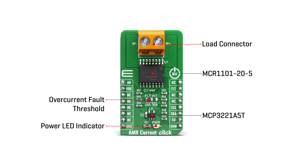
The AMR Current Click Board™ is based on the MCR1101-20-5 current sensor, which is an AMR based integrated current sensor from ACEINNA. The device has superior range and accuracy (0.6% typical total error at 25°C) and 2.0% max error over temperature. It also features a Superior Frequency Response - 1.5 MHz (typical 3dB BW) and a Fast output response time (300ns typical) with a Low Primary Resistance (0.9 mΩ). The MCR1101-20-5 current sensor is factory-calibrated to achieve low offset error and provide a precise analog voltage output that is linearly proportional to the conduction current (AC or DC) with sensitivity (mV/A) compatible with A/D converters and analog control loops in power systems.
VOC pin is connected directly to VOC (Reset) pin on mikroBUS™. Voltage on this pin defines the overcurrent detection OCD threshold level. Briefly driving this pin to VCC resets and rearms OCD circuit.
The AMR sensor device structure is designed to eliminate sensitivity to stray and common mode magnetic fields. Anisotropic magnetoresistance (AMR) makes use of a common material, Permalloy, to act as a magnetometer. Permalloy is an alloy containing roughly 80% nickel and 20% iron. The alloy's resistance depends on the angle between the magnetization and the direction of current flow. In a magnetic field, magnetization rotates toward the direction of the magnetic field and the rotation angle depends on the external field's magnitude. In a current sensor application, two of these resistors are connected in a Wheatstone bridge configuration to permit the measurement of the magnitude of the magnetic field produced by the current. AMR properties are well behaved when the film's magnetic domains are aligned in the same direction. This configuration ensures high sensitivity, good repeatability, and minimal hysteresis. During fabrication, the film is deposited in a strong magnetic field that sets the preferred orientation, or "easy" axis, of the magnetization vector in the Permalloy resistors. AMR has better sensitivity than other methods and reasonably good temperature stability. The AMR sensor has sensitivity which is approximately a linear function of temperature.
The AMR Current Click Board™ has fast and accurate overcurrent fault detection circuitry. The overcurrent fault threshold (I ) is user-configurable via an external resistor divider (FLT INT) and supports a range of 120% to 200% of the full-scale primary input (IP).
The sensor resistors are biased to the VCC supply voltage and produce a differential voltage that is ratiometric to VCC. This configuration is suited to applications where the A-to-D or other circuitry receiving the current sensor output signals are biased by and ratiometric to the same supply voltage as the current sensor. The ratiometric configuration provides increased gain and resolution compared to fixed gain.
The click board detects current by measuring the magnetic field generated by that current. Therefore it's important to consider the effect of externally generated magnetic fields, whether from another current flowing in the system, a magnet, or electromagnetic component.
The AMR Current Click Board™ also features the MCP3221 AST, which is a A/D converter with 12-bit resolution. This device provides one single-ended input with very low power consumption. This means that the AMR Current click can directly transfer the input from analog do digital because it contains the A/D converter.
Also featured on the AMR Current Click Board™ is the R7 resistor, which can be used if the communication is going directly to the mikroBUS™ device and is not used if you are using the A/D converter (MCP3221 AST).
The AMR Current Click Board™ can be used for various purposes, including server, telecom & industrial PWR supplies, power aggregation, over-current protection, motor balance, remote device monitoring and home automation control & IOT remote sensing, among others.
| Type | Current sensor |
| Applications | Server, telecom & industrial PWR supplies, power aggregation, over-current protection, motor balance, remote device monitoring and home automation control & IOT remote sensing, among others |
| On-board modules | MCR1101-20-5, an AMR based integrated current sensor from ACEINNA |
| Key Features | Low power consumption, Overcurrent fault detection, AMR based integrated current sensor, Superior Frequency Response (1.5 MHz) |
| Interface | Analog,I2C |
| Compatibility | mikroBUS |
| Click board size | M (42.9 x 25.4 mm) |
| Input Voltage | 5V |
This table shows how the pinout on the AMR Current Click Board™ corresponds to the pinout on the mikroBUS™ socket (the latter shown in the two middle columns).
| Notes | Pin | Pin | Notes | ||||
|---|---|---|---|---|---|---|---|
| Analog OUT | AN | 1 | AN | PWM | 16 | NC | |
| Reset | VOC | 2 | RST | INT | 15 | FLT | Fault |
| NC | 3 | CS | RX | 14 | NC | ||
| NC | 4 | SCK | TX | 13 | NC | ||
| NC | 5 | MISO | SCL | 12 | SCL | I2C Clock | |
| NC | 6 | MOSI | SDA | 11 | SDA | I2C Data | |
| NC | 7 | 3.3V | 5V | 10 | 5V | Power Supply | |
| Ground | GND | 8 | GND | GND | 9 | GND | Ground |
| Label | Name | Default | Description |
|---|---|---|---|
| LD1 | PWR | - | Power LED Indicator |
| J1 | FLT INT | Left | Overcurrent Fault Threshold Selector |
| TB1 | IN | - | Load Connector |
| Description | Min | Typ | Max | Unit |
|---|---|---|---|---|
| Supply Voltage | 4.5 | 5 | 5.5 | V |
| Primary Conductor | - | 1.3 | - | mΩ |
| Input Range | -20 | - | 20 | A |
| Sensitivity | - | 100 | - | mV/A |
AMR Current Click Board™
- amazon_main_image: https://www.thedebugstore.com/images/product/lg-amr-current-click-3812-front_1.jpg - amazon_other_image_1: https://www.thedebugstore.com/images/product/lg-amr-current-click-3812-back_1.jpg - amazon_other_image_2: https://www.thedebugstore.com/images/product/lg-amr-current-click-3812-fusion_1.jpg - amazon_other_image_3: https://www.thedebugstore.com/images/product/lg-amr-current-click-3812-shuttle_1.jpg - amazon_other_image_4: https://www.thedebugstore.com/images/product/lg-amr-current-click-3812-clicker_1.jpg - amazon_other_image_5: https://www.thedebugstore.com/images/product/lg-amr-current-click-3812-breadboard_1.jpg - amazon_other_image_6: https://www.thedebugstore.com/images/product/lg-amr-current-click-3812-breadboard_1.jpg - amazon_browse_node: 428655031 - mpn: MIKROE-3812 - backorder_label: If no stock shown above, check availability - badge: - widget:We provide a library for the AMR Current Click Board™ on our LibStock page, as well as a demo application (example), developed using MikroElektronika compilers. The demo can run on all the main MikroElektronika development boards.
Library provides functions for reading ADC value, and function for reading converted ADC data to mA
uint16_t amrcurrent_read_value ( void ) - Reads ADC current data.float amrcurrent_get_current ( void ) - Reads current data in mA.The application is composed of three sections :
void application_task ( )
{
    read_adc_val = amrcurrent_read_value(  );
    WordToStr( read_adc_val, demo_txt );
    mikrobus_logWrite( " - ADC value: ", _LOG_TEXT );
    mikrobus_logWrite( demo_txt, _LOG_LINE );

    Delay_ms( 100 );

    read_curr_val = amrcurrent_get_current(  );
    FloatToStr( read_curr_val, demo_txt );
    mikrobus_logWrite( " - Current value: ", _LOG_TEXT );
    mikrobus_logWrite( demo_txt, _LOG_TEXT );
    mikrobus_logWrite( "mA", _LOG_LINE );

    Delay_ms( 100 );

    mikrobus_logWrite( "-------------------------", _LOG_LINE );

    Delay_ms( 5000 );
}

The full application code, and ready to use projects can be found on our LibStock page.
Other mikroE Libraries used in the example:
Depending on the development board you are using, you may need a USB UART click, USB UART 2 click or RS232 click to connect to your PC, for development systems with no UART to USB interface available on the board. The terminal available in all MikroElektronika compilers, or any other terminal application of your choice, can be used to read the message.
The AMR Current Click Board™ is supported with mikroSDK - MikroElektronika Software Development Kit. To ensure proper operation of mikroSDK compliant Click board™ demo applications, mikroSDK should be downloaded from the LibStock and installed for the compiler you are using.
- attachments: [{"download_file":[{"download_file":"AMR Current Click Board™ Schematic"}],"download_filetype":[{"download_filetype":"pdf"}]},{"download_file":[{"download_file":"AceInna MCR1101 AMR Sensor Datasheet"}],"download_filetype":[{"download_filetype":"pdf"}]}] - condition: new - custom_product: false - mpn: MIKROE-3812 - google_product_category: Electronics - custom_label_0: Click Board - device_vendor: ACEINNA, Microchip Technology - device_type: MCR1101-20-5, MCP3221A5T-E/OT - warranty: 12 months - brand: MikroE - manufacturer: Mikroelektronika d.o.o. - target_keyword: AMR Current Click Board - brands: gid://shopify/Metaobject/56256004319 - breadcrumbs: ["gid://shopify/Collection/447955239135","gid://shopify/Collection/241680580797","gid://shopify/Collection/241545969853"] - customhs_code: 847330 - detailed_description: {"type":"root","children":[{"type":"heading","level":3,"children":[{"type":"text","value":"How Does The AMR Current Click Board™ Work?"}]},{"type":"paragraph","children":[{"type":"text","value":"The "},{"type":"text","value":"AMR Current Click Board™","bold":true,"italic":true},{"type":"text","value":" is based on the MCR1101-20-5 current sensor, which is an AMR based integrated current sensor from ACEINNA. The device has superior range and accuracy (0.6% typical total error at 25°C) and 2.0% max error over temperature. It also features a Superior Frequency Response - 1.5 MHz (typical 3dB BW) and a Fast output response time (300ns typical) with a Low Primary Resistance (0.9 mΩ). The MCR1101-20-5 current sensor is factory-calibrated to achieve low offset error and provide a precise analog voltage output that is linearly proportional to the conduction current (AC or DC) with sensitivity (mV/A) compatible with A/D converters and analog control loops in power systems."}]},{"type":"paragraph","children":[{"type":"text","value":""}]},{"type":"paragraph","children":[{"type":"text","value":"VOC pin is connected directly to VOC (Reset) pin on mikroBUS™. Voltage on this pin defines the overcurrent detection OCD threshold level. Briefly driving this pin to VCC resets and rearms OCD circuit."}]},{"type":"paragraph","children":[{"type":"text","value":"The AMR sensor device structure is designed to eliminate sensitivity to stray and common mode magnetic fields. Anisotropic magnetoresistance (AMR) makes use of a common material, Permalloy, to act as a magnetometer. Permalloy is an alloy containing roughly 80% nickel and 20% iron. The alloy's resistance depends on the angle between the magnetization and the direction of current flow. In a magnetic field, magnetization rotates toward the direction of the magnetic field and the rotation angle depends on the external field's magnitude. In a current sensor application, two of these resistors are connected in a Wheatstone bridge configuration to permit the measurement of the magnitude of the magnetic field produced by the current. AMR properties are well behaved when the film's magnetic domains are aligned in the same direction. This configuration ensures high sensitivity, good repeatability, and minimal hysteresis. During fabrication, the film is deposited in a strong magnetic field that sets the preferred orientation, or \"easy\" axis, of the magnetization vector in the Permalloy resistors. AMR has better sensitivity than other methods and reasonably good temperature stability. The AMR sensor has sensitivity which is approximately a linear function of temperature."}]},{"type":"paragraph","children":[{"type":"text","value":"The "},{"type":"text","value":"AMR Current Click Board™","bold":true},{"type":"text","value":" has fast and accurate overcurrent fault detection circuitry. The overcurrent fault threshold (I ) is user-configurable via an external resistor divider (FLT INT) and supports a range of 120% to 200% of the full-scale primary input (IP)."}]},{"type":"paragraph","children":[{"type":"text","value":"The sensor resistors are biased to the VCC supply voltage and produce a differential voltage that is ratiometric to VCC. This configuration is suited to applications where the A-to-D or other circuitry receiving the current sensor output signals are biased by and ratiometric to the same supply voltage as the current sensor. The ratiometric configuration provides increased gain and resolution compared to fixed gain."}]},{"type":"paragraph","children":[{"type":"text","value":"The click board detects current by measuring the magnetic field generated by that current. Therefore it's important to consider the effect of externally generated magnetic fields, whether from another current flowing in the system, a magnet, or electromagnetic component."}]},{"type":"paragraph","children":[{"type":"text","value":"The "},{"type":"text","value":"AMR Current Click Board™","bold":true},{"type":"text","value":" also features the MCP3221 AST, which is a A/D converter with 12-bit resolution. This device provides one single-ended input with very low power consumption. This means that the AMR Current click can directly transfer the input from analog do digital because it contains the A/D converter."}]},{"type":"paragraph","children":[{"type":"text","value":"Also featured on the "},{"type":"text","value":"AMR Current Click Board™","bold":true},{"type":"text","value":" is the R7 resistor, which can be used if the communication is going directly to the mikroBUS™ device and is not used if you are using the A/D converter (MCP3221 AST)."}]},{"type":"paragraph","children":[{"type":"text","value":"The "},{"type":"text","value":"AMR Current Click Board™","bold":true},{"type":"text","value":" can be used for various purposes, including server, telecom & industrial PWR supplies, power aggregation, over-current protection, motor balance, remote device monitoring and home automation control & IOT remote sensing, among others."}]},{"type":"heading","level":3,"children":[{"type":"text","value":"SPECIFICATIONS"}]},{"type":"paragraph","children":[{"type":"text","value":"Type\nCurrent sensor\nApplications\nServer, telecom & industrial PWR supplies, power aggregation, over-current protection, motor balance, remote device monitoring and home automation control & IOT remote sensing, among others\nOn-board modules\nMCR1101-20-5, an AMR based integrated current sensor from ACEINNA\nKey Features\nLow power consumption, Overcurrent fault detection, AMR based integrated current sensor, Superior Frequency Response (1.5 MHz)\nInterface\nAnalog,I2C\nCompatibility\nmikroBUS\nClick board size\nM (42.9 x 25.4 mm)\nInput Voltage\n5V"}]},{"type":"heading","level":3,"children":[{"type":"text","value":"PINOUT DIAGRAM"}]},{"type":"paragraph","children":[{"type":"text","value":"This table shows how the pinout on the "},{"type":"text","value":"AMR Current Click Board™","bold":true},{"type":"text","value":" corresponds to the pinout on the mikroBUS™ socket (the latter shown in the two middle columns)."}]},{"type":"paragraph","children":[{"type":"text","value":"Notes\nPin\nPin\nNotes\nAnalog OUT\nAN\n1\nAN\nPWM\n16\nNC\nReset\nVOC\n2\nRST\nINT\n15\nFLT\nFault\nNC\n3\nCS\nRX\n14\nNC\nNC\n4\nSCK\nTX\n13\nNC\nNC\n5\nMISO\nSCL\n12\nSCL\nI2C Clock\nNC\n6\nMOSI\nSDA\n11\nSDA\nI2C Data\nNC\n7\n3.3V\n5V\n10\n5V\nPower Supply\nGround\nGND\n8\nGND\nGND\n9\nGND\nGround"}]},{"type":"heading","level":3,"children":[{"type":"text","value":"ONBOARD SETTINGS AND INDICATORS"}]},{"type":"paragraph","children":[{"type":"text","value":"Label\nName\nDefault\n Description\nLD1\nPWR\n-\nPower LED Indicator\nJ1\nFLT INT\nLeft\nOvercurrent Fault Threshold Selector\nTB1\nIN\n-\nLoad Connector"}]},{"type":"heading","level":3,"children":[{"type":"text","value":"AMR CURRENT CLICK ELECTRICAL SPECIFICATIONS"}]},{"type":"paragraph","children":[{"type":"text","value":"Description\nMin\nTyp\nMax\nUnit\nSupply Voltage\n4.5\n5\n5.5\nV\nPrimary Conductor\n-\n1.3\n-\nmΩ\nInput Range\n-20\n-\n20\nA\nSensitivity\n-\n100\n-\nmV/A"}]},{"type":"heading","level":3,"children":[{"type":"text","value":" "}]}]} - summary:The AMR Current Click Board™ has fitted ±20A fully integrated bi-directional analogue output current sensors that deliver both high accuracy and high bandwidth. This state-of-the-art Anisotropic Magneto Resistive (AMR) sensor technology provides inherently low noise, excellent linearity and repeatability.
The AMR Current Click Board™ is supported by a mikroSDK compliant library, which includes functions that simplify software development. This Click Board™ comes as a fully tested product, ready to be used on a system equipped with the mikroBUS™ socket.